GSM Activate GSM Auto Dialler Plus User manual

GSM 4G AUTO DIALLER PLUS
Control and Monitoring from your mobile phone
Page 1
MODEL 4GAD+

Contents
● 2 - Contents.
● 3 - Product Information.
- Specification.
● 4 - PCB Reference.
● 5 - Installing Your Simcard.
- Signal Strength Test.
● 6 - Storing and Deleting Contact Numbers.
● 7 - How to Store Input Text Messages.
- How to Set Phone Call Alerts and Text Messages.
● 8 - Activating the Output Relays
● 9 - Activating Inputs
● 10 - Mains Failure Monitoring
- Battery Back Up
- Microphone & Speaker (Optional)
● 11 - Temperature Monitoring
● 12 - Quick Programming Guide
- Factory Reset
● 13 - Important Installer Notes
Page 2

Page 3
Product Information
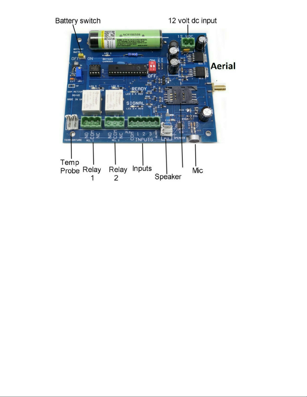
The GSM Auto Dialler Plus is a multi purpose unit with both 2G,3G &4G capabilities. It is
compatible with all alarm panels with negative triggering through three inputs and one alarm
input as well as having 2 relay outputs for switching on or off external devices such as,
temperature monitoring, mains failure monitoring with battery back up and a optional
microphone and speaker are available seperately for two way communication.
Specification
● GSM Frequency: Quadband Frequency 850/900/1800/1900/2100 Mhz
● 4G Bands : B1 -B5, B7 - B8, B12 - B14, B18 - B20, B25 , B26, B28 , B66, B71
● Power Supply Voltage: 9 - 24 volts DC
● Current Used in Standby Mode: 35 Milliamps
● Max Current: Up to 2 Amps
● Standard 2G 3G 4G Simcard
● No landline required
● Dimensions - L170 x W120 x H60mm
● Weight - 360 grams
● Operating Temperature: -10…+40°C
● Signal Strength Function
● Stay Active Simcard Function
● Watchdog and Self Repair Function
● 3 Inputs and 1 Alarm Input
● 2 - 10 Amp Relay Outputs
● 1 Standalone Alarm Sensor Input
● Temperature Reading by Text Message
● Temperature Alarm Controller
● Optional Speaker to speak to people near the unit
● Optional Microphone you can call into and listen to the surroundings of the unit.
● Mains Failure and Restore Alarm
● Battery Backup for up to 24 hours standby

PCB Reference
IMPORTANT - PLEASE READ
PLEASE MAKE SURE YOU DISCONNECT THE POWER FROM POWER INPUT AND
REMOVE THE BATTERY LINK WHEN YOU FIT THE SIMCARD AND PLACE THE
SIMCARD WITH THE CLIPPED CORNER FACING OUT WARDS.
SEE PICTURE ABOVE.
Signal LED (blue) - The blue LED flashes once per second indicating a signal has been found.
Ready LED (green) - The green LED will come on when the unit is ready for operation.
Charger LED (red) - The red LED indicates that the battery is in charging mode.
Battery Switch - push on to turn battery backup on (battery only charges with battery switch on)
Dipswitch
The dialler can work on 2G, 3G & 4G networks. The module it uses works worldwide with all
simcard (see page 3 for applicable bands)
You can choose which frequency the unit will use at the start by using the dipswitch
combinations below
1 - If Dipswitch 1 Set to OFF & Dipswitch 2 Set to OFF = Unit boots up in 2G
2 - If Dipswitch 1 Set to ON & Dipswitch 2 Set to OFF = Unit boots up in 3G
3 - If Dipswitch 1 Set to ON & Dipswitch 2 Set to ON = Unit boots up in 4G
Page 4
Figure 1

Installing your Simcard
New SIM cards will need registering before they can be used. Full details of how this is done
can normally be found in the SIM card pack. It will normally require that the SIM card is
inserted into a mobile phone, a number dialled and instructions followed. While the SIM is in
the mobile phone it would be a good time to disable call diverts, ring back and to disable
features such as voicemail and text alerts.
The Auto Dialler has a built in “sim active function” which keeps track of the unit’s activity. If
there has been no usage for 6 weeks, it will send a text message to a preset recorded number
to keep the simcard active. This then eliminates the problems of sims being shut down if they
are unused for 3 months.
Activate and put credit on your simcard and disable voicemail using the following codes
Vodaphone: call 1210 Tesco call 2915
T-Mobile: call 222 O2 call 1760
Orange: call 4502 Giff Gaff call 1626
EE - send the text message command VM OFF to 150
ENSURE THE UNIT IS POWERED DOWN AND BATTERY TURNED OFF BEFORE
INSERTING THE SIMCARD.
1: Slide back the sim door and lift it up.
2: Slide the simcard in to the door making ensuring that the clipped corner of the simcard lines
up with the clipped corner of the simcard holder.
3: Close the sim door.
4: Slide the sim door to lock the simcard in place.
Connect 9 through to 24 volts DC to the input connector as per figure 1. Once power has been
applied (referring to figure 1) the blue network LED light will flash once every second. Once a
signal has been found the green LED will come on and stay on indicating the unit is now ready
for use.
Signal Strength
Signal strength can be checked by sending the text command #status#
The unit will reply back with a score from 1 - 30. Anything less than a score of 10 will make the
unit unreliable.
We recommend doing a signal strength on 2G , 3G and 4G (see diagram page 4) to see which
frequency is strongest
Note if using Giff Gaff simcards please disable balance notifications in your Giff Gaff
account
Page 5

Programming Contact Numbers
The 4G Auto Dialler Plus has four inputs for a connection to electrical equipment plus separate
hardware for temperature, mains failure and external sensing. When these are triggered the
unit will call or text up to 3 separate numbers which can be stored on to the unit.
To programme the numbers you want to use, follow the examples below by sending the text
message command to the simcard in the auto dialler.
NOTE - We have colour coded the symbols hash (#) and (=) to make programming easier.
To programme the mobile numbers please follow this example:
#PH1=07712345678# - Stores the mobile/landline phone number as contact no: 1
#PH2=01903123456# - Stores the mobile/landline phone number as contact no: 2
#PH3=07123456789# - Stores the mobile/landline phone number as contact no: 3
A maximum of 3 phone numbers in total.
To delete a stored number use the following example
#PH1=DELETE# - YOU CANNOT DELETED NUMBER 1 - ONLY OVERRIDE
#PH2=DELETE# - This deletes stored contact number 1
#PH3=DELETE# - This deletes stored contact number 1
NOTE
Please send one message at a time and wait for the auto dialler plus to send you the text
Acknowledgement ‘NUMBER STORED’ before you try to send another number. This may take a
few minutes depending on how busy the network is at the time.
Page 6

Page 7
How to Programme the (SMS) Text Message
You can now change the alarm message to one of your choosing.
To change the message send the text command as follows:
#MESS1=YOURMESSAGE# This sets your custom message for input 1
#MESS2=YOURMESSAGE# This sets your custom message for input 2
#MESS3=YOURMESSAGE# This sets your custom message for input 3
#MESS4=YOURMESSAGE# This sets your custom message for input 4
The default message is INPUT ACTIVATED
Note - your can only use a maximum of 30 characters including spaces for you customised
message.
Telephone Call Alerts
The auto dialler can be programmed to send you a telephone call after each text alarm has
been sent. You will receive approximately three ring tones. The unit will then hang up
automatically. This prevents call charges being incurred.
To set call alerts to ON please send the text command
#CALL=ON#
The unit will reply back with “call on”
To disarm call alerts please send the text command
#CALL=OFF#
If the function has been set to ON you will receive a text message and shortly after a phone call.

Page 8
How to Use the Relay Outputs
The 4G Auto Dialler has two relay outputs which can be used to switch on external devices
such as lighting, sirens etc…
Relay 1 is independent and can be activated by SMS message
Relay 2 is independent and can be activated by SMS message
Auto Relay Trigger (Relay 2)
Relay 2 can be used to turn on a siren or lighting etc , for approximately 17 seconds
automatically when an input or alarm have been triggered. Please be aware of any conflicts
this may cause if you are already using relay 2 as an independently activated relay.
To turn this function on please send the SMS
#AUTO=ON# this will turn the AUTO function on for relay 2 only
#AUTO=OFF# this will turn the AUTO function off for relay 2 only (default setting is off)
Activation by SMS Text Message
By texting the unit you can turn relay 1 and 2 ON or OFF individually. Below, are examples on
how to do this.
#REL1=ON# This will turn on relay 1
#REL1=OFF# This will turn off relay 1
#REL2=ON# This will turn on relay 2
#REL2=OFF# This will turn off relay 2
After each operation the unit will reply with the status report REL 1 ON/OFF
It is possible to pulse relay 1 & 2 for a period of 17 seconds. You will need to send the text
message as follows.
#PUL=REL1# - This will pulse relay 1 for 17 seconds
#PUL=REL2# - This will pulse relay 2 for 17 seconds
The unit will reply back with REL1 or REL2 PULSE
.

Page 9
Alarm Input - Manual Reset
Alarm Input
This is triggered by a negative pulse eg: pulled to the ground for a period of not less than one
second. Before this can be triggered you must activate the alarm input by sending the text
command as follows. The units will need manually activating again once triggered by a text
message.
#ALARM=ON# - This will activate the alarm if the input is pulled to the ground. You will
receive a text message reading ALARM TRIGGERED
#ALARM=OFF# - This will deactivate the alarm. Pulling the input to the ground will mean you
will receive NO notifications.
Using the Inputs
Inputs 1 2 & 3 - Automatically Reset
Inputs 1 2 & 3are triggered by a negative pulse eg: pulled to the ground for a period of not less than one
second. The image (at the bottom of the page) 1s a typical application of how to connect the unit to an
alarm panel.
Input 1 and Input 2 are constantly monitored by the auto dialler and will react immediately when an input
is pulled to the ground.
The inputs will automatically reset when the input triggers are cleared/ reset. The
Auto-Dialler will then be ready for the next trigger input.

Page 10
Mains Failure Alarm
By connecting to the mains power using a 9/24v power supply the auto dialler can act as a
mains failure alarm. It will monitor the power connected to the power input and send a text
message alert if the power is disconnected.
When the power is disconnected for a period of 4 minutes, you will receive the text message
alert POWER LOSS. When the power is restored you will receive the text message alert
POWER RESTORED.
Battery Backup
When power has been disconnected the unit will revert to the onboard battery backup. The
battery back will operate the auto dialler for up to 24 hours before it will need to be recharged
by connecting 12 volts back to the power input.
NOTE - The battery will only work when the battery is switched on. If you do not switch the
battery switch on then the battery backup will not work. Please refer to PCB reference on
page 4
Microphone and Speaker (optional extra purchased seperately)
The unit has an onboard microphone. To activate it, make a phone call to the units number.
After a few rings the call will be answered and you will be able to hear what is happening in
the surroundings of the unit. To cancel this operation simply hang up.
For two way audio, that will enable you to communicate with someone in the vicinity of the unit
please purchase our speaker from the accessories page on the website. This can be plugged
into the side socket of the unit to enable two way conversation.

Page 11
Controlling The Temperature
The Microprocessor will scan the temperature parameters every 3 minutes, when the temperature
goes outside of the temperature parameters this will generate a text alarm sent to the users indicating
the current temperature and turn on relay 1.
When the temperature returns into the temperature parameters, a text will be generated to let users
now temperature is normal, and relay 1 will be turned off
Text Commands
#+09*20# This will save the parameter settings for plus 9 degrees to plus 20 degrees
#-10*20# This will save the parameter settings for minus 10 degrees to minus 20 degrees
*NOTE YOU CANNOT MIX MINUS AND PLUS TEMPERATURES - PLEASE USE + OR - SYMBOL
#START# will start the temperature reading / temperature alarm
#STOP# will stop the temperature reading / temperature alarm
*Note In the event of a power loss the unit will remember if it was in stop or start mode
#TEMP# at any time you can text this to get a temperature reading

Page 11
Quick Reference

Page 13
Important Installer Notes
● When installing the aerial antenna cable please ensure that the cable leaves the box by the
shortest possible route and is not coiled up and left inside the box
● Do not stick the aerial onto any metal surface. This will degrade the signal strength
received.
● Please remove all voicemail functions from the simcard before installing it into the Auto
Dialler. All major UK network voicemail removal codes are shown on page 5
● Before commissioning, please ensure the signal strength is sufficient by sending the text
message #STATUS#
We strongly recommend you need a score of at least 10. Also try the signal using both the
2G 3G & 4G via dipswitch 1 & 2
● If you do not receive a good signal, please reposition the aerial antenna to improve the
signal strength or alternatively change the network provider as signal strength can vary
between providers.
For more technical support please browse the FAQ’s on our website www.gsm-activate.co.uk
or alternatively email our technical support team at te[email protected] and we will
reply or call back within 24 hours Monday - Friday.
17/02/2021 AD
This manual suits for next models
1
Table of contents
Popular Control System manuals by other brands

Volvo Penta
Volvo Penta Electronic Control System installation instructions

Syris
Syris SY120SA operating manual

Crestron
Crestron 3 Series Operation guide

Sutter Instrument
Sutter Instrument SmartShutter Lambda SC Operation manual

Daikin
Daikin D-BACS Design guide

Siemens
Siemens SIMATIC PCS 7 Function manual