Gatt MX-6-FX User manual

MX SERIES
PROFESSIONAL MIXER
MX-6-FX
MX-8-FX
MX-6-FXU
MX-8-FXU

The symbol is used to indicate that some hazardous live terminals are
involved within this apparatus, even under the normal operating conditions,
which may be sufficient to constitute the risk of electric shock or
death.
The symbol is used in the service documentation to indicate that specific
component shall be replaced only by the component specified in that
documentation for safety reasons.
Protective grounding terminal
Alternating current/voltage
Hazardous live terminal
ON: Denotes the apparatus is turned on
OFF: Denotes the apparatus is turned off.
WARNING: Describes precautions that should be observed to prevent the danger
of injury or death to the operator.
CAUTION: Describes precautions that should be observed to prevent danger of
the apparatus.
IMPORTANT SAFETY INSTRUCTIONS
·Read these instructions.
·Keep these instructions.
·Heed all warning.
·Follow all instructions.
Water & Moisture
·
CAUTION
RISK OF ELECTRIC SHOCK
DO NOT OPEN
IMPORTANT SAFETY SYMBOLS
The apparatus should be protected from moisture and
rain, can not used near water, for example: near bath-
tub, kitchen sink or a swimming pool, etc.
·Heat
The apparatus should be located away from the heat source such as radiators,
stoves or other appliances that produce heat.
As a resultof theseefforts,modificationsmaybe made from time toexistingproductswithout prior notice.
Specifications and appearance may differ from those listed or illustrated.
Measuring conditions:
1: 1kHz rel.to 0 dBu; 20 Hz - 20 kHz, line input; main output; unity gain.
2: 20Hz - 20kHz; measured at main output. Channels 1 - 4 unity gain: EQ flat; al channels on main mix;
channels 1/3 as far left as possible, channels 2/4 as far right as possible. Reference = +6 dBu.
20
MX-6-FX / MX-8-FX
MX-6-FXU / MX-8-FXU

·Power Supply
The apparatus should be connected to the power supply only of the type as marked
on the apparatus or described in the manual. Failure to do could result in damage
to the product and possibly the user.
Unplug this apparatus during lightning storms or when unused for long periods
of time.
·Ventilation
Do not block areas of ventilation opening. Failure to do could result in fire. Always
install accordance with the manufacturer's instructions.
·Fuse
To prevent the risk of fire and damaging the unit, please use only of the
recommended fuse type as described in the manual. Before replacing the fuse,
make sure the unit turned off and disconnected from the AC outlet.
·Electrical Connection
Improper electrical wiring may invalidate the product warranty.
·Cleaning
·Object and Liquid Entry
Clean only with a dry cloth. Do not use any solvents such as benzol or alcohol.
·Servicing
Do not implement any servicing other than those means described in the manual.
Refer all servicing to qualified service personnel only.
·Only use accessories/attachments or parts recommended by the manufacturer.
·Warning
Please remember the high sound pressure do not only temporarily damage your
sense of hearing, but can also cause permanent damage. Be careful to select a
suitable volume.
Objects do not fall into and liquids are not spilled into the inside of the apparatus
for safety.
·Power Cord and Plug
Protect the power cord from being walked on or pinched particularly at plugs, convenience
receptacles, and the point where they exit from the apparatus.
Do not defeat the safety purpose of the polarized or grounding-type plug. A
polarized plug has two blades with one wider than the other. Agrounding type
plug has two blades and a third grounding prong. The wide blade or the third
prong is provided for your safety. If the provided plug does not fit into your outlet,
refer to electrician for replacement.
19
USA/Canada 120 V~, 60 Hz, MXUL5 adapter
Dimenstions
MX-6-FX
MX-8-FX
Dimensions (H x W x D)
Dimensions (H x W x D)
weight (net) 47mm/ 37.5mmx 240mmx 184mm
47mm/ 37.5mmx 240mmx 237mm
approx. 1.2 kg
Mains voltage
U.K./Australia 240 V~, 50 Hz, MXUK5 adapter
Europe 230 V~, 50 Hz, MXEU5 adapter
Japan 240 V~, 60 Hz, MXJP5 adapter
weight (net) approx. 1.5 kg
MX-6-FXU
MX-8-FXU
Dimensions (H x W x D)
Dimensions (H x W x D)
weight (net) 47mm/ 37.5mmx 240mmx 184mm
47mm/ 37.5mmx 240mmx 237mm
approx. 1.2 kg
weight (net) approx. 1.5 kg
Power supply
Power consumption MX-6-FX: 15 W
MX-8-FX: 17 W
MX-6-FXU: 15 W
MX-8-FXU: 17 W
MX-6-FX / MX-8-FX
MX-6-FXU / MX-8-FXU

TABLE OF CONTENTS
1.INTRODUCTION...............................................................2
1.1 General mixing console functions..................................................... .......................2
1.2 The user’s manual..................................................................................................3
1.3 Before you get started.............................................................................................3
2 . C O N T R O L E L E ME N T S A N D C O N N E C T O R S . . . . . . . . . . . . . . . . . . . . . 4
2.1 Mono channels.......................................................................................................4
2.2 Stereo channels.....................................................................................................6
2.3 Connector carry of the main section..........................................................................7
2.4 .........................................................................................................9
Main section
4.INSTALLTION................................................................15
4.2Audio connections................................................................................................15
4.1 Mains connection.................................................................................................15
5.SPECIFICATIONS..........................................................17
1
2.5 ....................................................................................11Digital effects processor
2.6 ...........................................................................................12Rear Panel Section
3.APPLICATION............................................................... 13
3.1 ....................................................................................13Digital effects processor
3.2 ...........................................................................................14Rear Panel Section
Main outputs
Type
Impedance
Max.output level
XLR electronically balanced
approx.240 bal./ 120 unbal.Ω Ω
+28 dBu
Control room outputs
Type
Impedance
Max.output level
1/4"TS connector, unbal.
approx. 120 Ω
+22 dBu
Headphones output
Type
Max.output level 1/4"TRS connector, unbalanced
+19 dBu / 150 (+25 dBu)Ω
2
Main mix system data
Noise
Main mix @ -∞,
Channel fader -∞
Main mix @ 0 dB,
Channel fader -∞
Main mix @ 0 dB,
Channel fader @ 0 dB
-106 dB / -109 dBA-weighted
-95 dB / -98 dBA-weighted
-84 dB / -87 dBA-weighted
EQ mono channels
EQ stereo channels
Low
Mid
High
Low
Mid
80 Hz / 15 dB
2.5 kHz / 15 dB
12 kHz / 15 dB
80 Hz / 15 dB
2.5 kHz / 15 dB
High 12 kHz / 15 dB
Aux sends
Stereo aux return
Type
Impedance
Max.output level
1/4"TS connector, unbalanced
approx. 20 kΩ
+22 dBu
1/4"TRS connector,
Type electronically balanced
approx.20k bal./10k unbal.Ω Ω
+22 dBu
Impedance
Max.input level
18
MX-6-FX / MX-8-FX
MX-6-FXU / MX-8-FXU MX-6-FX / MX-8-FX
MX-6-FXU / MX-8-FXU

2
MX-6-FX / MX-8-FX
MX-6-FXU / MX-8-FXU
17
MX-6-FX / MX-8-FX
MX-6-FXU / MX-8-FXU
MX-6-FX / MX-8-FX
MX-6-FXU / MX-8-FXU
3
The foot switch connects the two poles momentarily
strain relief clamp
sleeve
tip
sleeve tip
ground shield signal
For connection of balanced and unbalanced plus,
rig and sleeve have to be bridged at the stereo plug
Headphones connection
with 1/4"TRS connector
strain relief clamp
sleeve
tip
sleeve tip
ground shield left signal
F ig. 4 . 4: S tere o p lug f or he a dphones c onne c tion
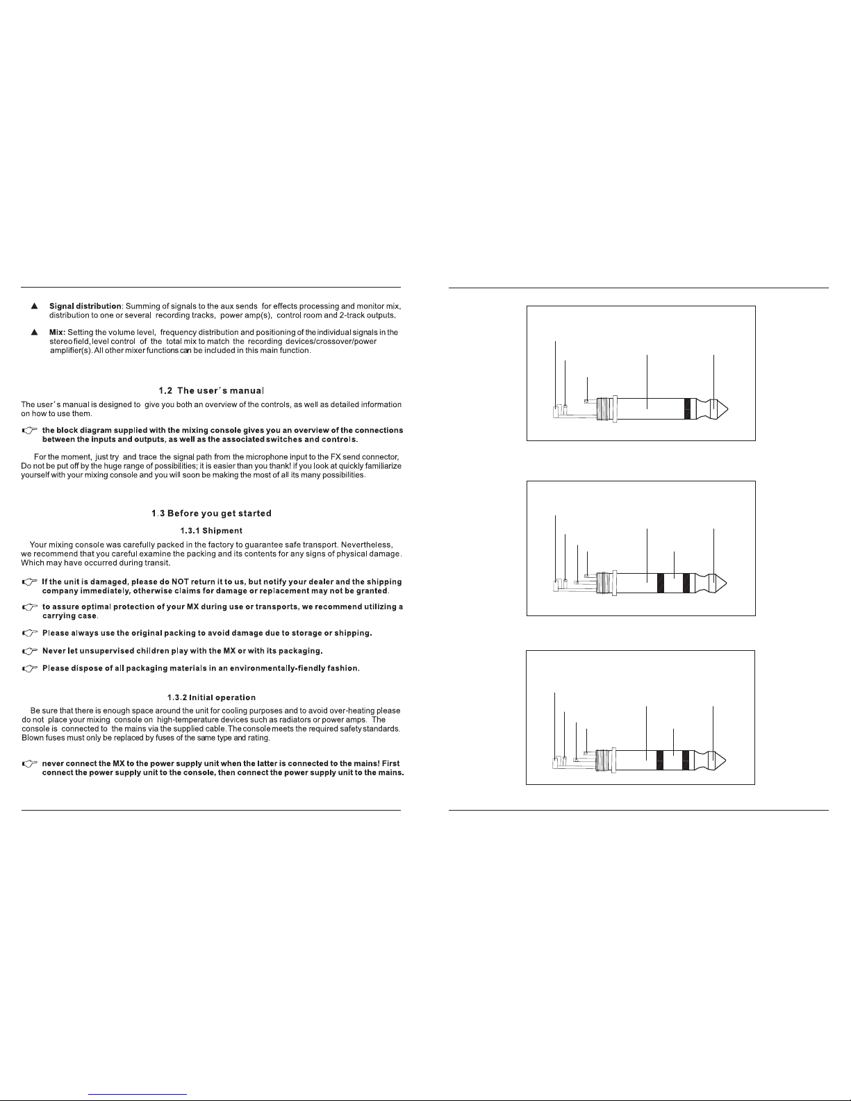
F ig . 4 . 3 : 1 /4"s tere o p lug
F ig . 4 . 2 : 1 /4"mono plug
ring right signal
ring
strain relief clamp
sleeve
tip
sleeve tip
ground shield hot (+ ve)
ring cold (- ve)
ring
Balanced use of
1/4"TRS connector
Unbalanced use of
1/4"TRS connector
16
MX-6-FX / MX-8-FX
MX-6-FXU / MX-8-FXU MX-6-FX / MX-8-FX
MX-6-FXU / MX-8-FXU

Please note that all unit must be properly grounded. For your own safety, you should never
remove any ground connectors from electrical devices or power cables, or render them
inoperative.
Please sure that only qualified people install and operate the mixing console.During
installation and operation, the user must have sufficient electrical contact to earth,
otherwise electrostatic discharges might affect the operation of the unit.
2.CONTROL ELEMENTS AND
CONNECTORS
This chapter describes the various control elements of your mixing console. All controls, switches
and connectors will be discussed in detail.
2.1 Mono channels
Fig. 2.1: Connectors and controls on the mono channels
4
1
+10 -40+10 +60
TRIM
dB/dBu
BAL
OR
UNBA L
LINE
IN
MIC
0
- +15
8
L R
0
-15 +15
0
-15 +15
0
-15 +15
EQ
PAN
HIG H
12 KHz
MID
2.5 KHz
LOW
80 Hz
FX
CLIP
0
- +15
8
1
LEVEL
LOW CUT
75H z
18 dB/Oct
12
3
15
4.1 Mains connection
You will need a larger number of cable for the various connections to and from the console. The
illustrations below show. The wing of these cables. Be sure to use only high-grade cable.
Please use commercial RCAcables to wire the 2-track inputs and outputs.
You can, of course, also connect unbalanced devices to the balanced input/outputs. Use either mono
plugs, or ensure that ring and sleeve are bridged inside the stereo plug (or pins 1 & 3 in the case of XLR
connectors).
Caution! Never use unbalanced XLR connectors (PIN 1 and 3 connected) on the MIC input
connectors when using the phantom power supply.
4.INSTALLATION
Connect the power supply to the 3-pin mains connector on the rear of the console. Use the AC adapter
supplied to connect the console to the mains. The adapter complies with all applicable safety standards.
Please use only the power supply unit provided with the console.
4.2 Audio connections
Fig. 4.1: XLR connections
Please use only the power supply unit provided with the console.
AC POWER IN
For unbalanced use pin 1 and pin 3 have to be bridged
Balanced use with XLR connectors
1=groud / shield
2=hot (+ve)
3=cold (-ve)
1
2312
3
Input Output
Never connect the MX to the power supply unit while the latter is connected to the mains!
First connect the console to the power supply unit, then connect the power supply unit to
the mains.
MX-6-FX / MX-8-FX
MX-6-FXU / MX-8-FXU MX-6-FX / MX-8-FX
MX-6-FXU / MX-8-FXU

The circuitry of the British EQs is based on the technology used in the bast-known top-of-the-line consoles
and providing a warm sound without any unwanted side effects. The result are extremely musical equalizes
which, unlike simple equalizers, cause no side effects such as phase shifting or bandwidth limitation, even
with extreme gain settings of +15 dB.
All mono input channelsinclude a 3-band equalizer. All bands provideboost or cut of up to 15 dB. In the
central position, the equalizer is inactive.
The upper (HI) and the lower band (LO) are shelving filters that increase or decrease all frequencies above
or below their cut-off frequency.The cut-off frequencies of the upper and lower band are 12 kHz and 80 Hz
respectively. The mid band (602/802/1002/1202) is configured as a peak filter with a center frequency of
2.5kHz
Inaddition, the monochannels are equippedwitha steepLOW CUT filter
designedto eliminate unwanted low-frequenty signalcomponents. Thesecanbenoisecreated byband-held
microphones,subsonicnoiseorplosivesoundscreatedbyhighlysensitivemicrophones.
(slopeat18 dB/oct.,-3dBat75 Hz)
L O W C U T
E Q
pl ea s e r e me m be r t ha t y ou c a n o nly u s e e i the r t he m i c ro ph o n e o r t h e l in e i n p ut o f a
c h a n ne l a t a n y o n e t ime . Y o u c a n n e v e r u s e b o th s i mu l tan e o us l y !
T R IM
Use theTRIM control to adjust the input gain. This control should always be turned fully counterclock
-wise whenever you connect or disconnect a signal source to one of the inputs.
5
FX sendsenableyoutofeedsignalsviaa variablecontrolfrom one ormorechannelsandsumthese signalsto
bus.Thebusappearsattheconsole’s FXsendoutputandcanbefedfromtheretoanexternaleffectsdevice.The
returnfromtheeffectsunitisthen broughtbackintotheconsoleontheauxreturnconnectorsornormalchannel
inputs. EachFXsend ismono and featuresupto+15dBgain.
F X
The scale has 2 different value range: the first value range (+10 to +60 dB) refers to the MIC input and
shows the amplification for the signals fed in there.
The second value range (+10 to +60 dB) refers to the line input and shows its sensitivity. The settings
for equipment with standard line-level signals (-10dB or +4dBu) look like this: While the TRIM control is
turned all the way down, connect your equipment. Set the TRIM control is turned to the external devices
standard output level. If that unit that an output signal level display, it should show 0 dB during signal
peaks. For +4 dBu, turn up TRIM sightly. for -10 dBV a bit more.Tweaking is done using the CLIPLED.
Each mono input channel offers a balanced microphone input via the XLR connector and also
features switchable +48 V phantom power supply for condenser microphones. The ME preamps
provide undistorted and noised-free gain as is typically known only from costly outboard preamps.
P leas e mute your play bac k s ys tem before you ac tive the phantom power s upply to prevent
s witch-on thumps being dir ected to your louds peak ers . P leas e a ls o no te the ins truc tions in
c ha pte r 2.4“M ain s e c tion”.
MIC
Each mono input also features a balanced line input on a connector. Unbalanced devices
(mono jacks) can also be connected to these inputs. 1/4
L I N E I N
14
3 4
1 2
+10 -40+10 +60
TRIM
dB/dBu
BAL
OR
UNBAL
LINE
IN
MIC
+10 -40+10 +60
TRIM
dB/dBu
BAL
OR
UNBAL
LINE
IN
MIC
MAI N OUT
L R L R
CTR L ROOM OU T
LIN E IN 5/6
L
R
MONO
BAL
OR
UNBAL
LINE IN 7/8
MONO
BAL
OR
UNBAL
LIN E IN9/1 0 LIN E IN 11/1 2 SEND FX
PHONES
0
- +15
8
L R
0
-15 +15
0
-15 +15
0
-15 +15
EQ
PAN
HIGH
12KHz
MID
2.5KHz
LOW
80Hz
FX
CLIP
0
- +15
8
3
LEVE L
0
- +15
8
L R
0
-15 +15
0
-15 +15
0
-15 +15
EQ
PAN
HIGH
12KHz
MID
2.5KHz
LOW
80Hz
FX
CLIP
0
- +15
8
4
LEVE L
0
- +15
8
L R
BAL
CLIP
0
- +15
8
5/6
LEVEL
0
- +15
8
L R
BAL
CLIP
0
- +15
8
7/8
LEVEL
0
- +15
8
L R
BAL
CLIP
0
- +15
8
9/10
LEVEL
0
- +15
8
L R
BAL
CLIP
0
- +15
8
11/12
LEVEL
+4
-10
+4
-10
+4
-10
+4
-10
L
R
CD/TAPE
IN OU T
0
- +15
8
MAIN MIX
10
0
10
15
20
25
30
40
60
8
MONO
BAL
OR
UNBAL
L
R
L
R
+10 -40+10 +60
TRIM
dB/dBu
BAL
OR
UNBAL
LINE
IN
MIC
+10 -40+10 +60
TRIM
dB/dBu
BAL
OR
UNBAL
LINE
IN
MIC
0
- +15
8
L R
0
-15 +15
0
-15 +15
0
-15 +15
EQ
PAN
HIGH
12KHz
MID
2.5KHz
LOW
80Hz
FX
CLIP
0
- +15
8
1
LEVEL
0
- +15
8
L R
0
-15 +15
0
-15 +15
0
-15 +15
EQ
PAN
HIGH
12KHz
MID
2.5KHz
LOW
80Hz
FX
CLIP
0
- +15
8
2
LEVEL
MONO
BAL
OR
UNBAL
L
R
FX FX FX F X
+48 V
POWER
0
- +15
8
0
- +15
8
FX SEN DS
L R
20
0
6
CLIP
PROG RAM
(PUSH)
REVERB 00-39
ER/DLY 40-59
MOD 60-73
PITCH 74-79
MULTI 80-99
LOW CUT
75Hz
18 dB/Oct
LOW CUT
75Hz
18 dB/Oct
LOW CUT
75Hz
18 dB/ Oct
LOW CUT
75Hz
18 dB/Oct
M E 1 2 0 2 F X
TAPE
TO MIX
TAPE
TO CTR L
FX
TO CTR L
PHON ES
PHAN TOM
HIGHQUALITY18 INPUT 2/2 BUS MIXER 24-BIT DSP FX PROCESSOR
12
3
12
3
12
3
12
3
-3
-6
-10
-15
-20
CLP 24-BITDUALENGINEDSP
24-BITA/D&D/ACONVERTER
88
TAPE
+ 6. .6 6
D ig i ta l A u d io w o r k s ta ti on
MIDI s o u nd m o dul e
H e a d ph o ne
m i c r o p h o n e
A c t iv e m o n ito r
C D p l a y e r
G u i ta r
k e y b o a r d
F ig. 3 . 2 : L ive a pplica tion of the 1 20 2F X
M D r e c o r d e r
3 . 2 L i v e s o u n d
MX-6-FX / MX-8-FX
MX-6-FXU / MX-8-FXU MX-6-FX / MX-8-FX
MX-6-FXU / MX-8-FXU

The PAN control determines the position of channel signal within the stereo image. This control features a
constant-power characteristic, which means the signal is always maintained at a constant level, irrespective
of position in the stereo panorama.
PAN
The LEVEL control determines the level of the channel signal in the main mix
LEVEL
The CLIP LED”s of the mono channels illuminate when the input signal is driven too high, which could
cause distortion. If this happens, use the TRIM control to reduce the preamp level until the LED does not
light anymore.
CLIP
2.2 Stereo channels
6
As the name suggests, the FX sends of the MX mixingconsoles are intended to drive effects devices(reverb,
delay, etc.) and are therefore configured post-fader. This means that the mix between dry signal and effect
remains at the level determined by the channel’s aux send, irrespective of the level fader setting. If this were
not the case, the effects signal of the channel would remain audible even when the fader is lowered to zero.
With ME mixing consoles the channelfader is called LEVEL control.
In the MX-6-FX/ MX-8-FX /MX-6-FXU/ MX-8-FXU, the FX send is routed directly to the built-in effects processor.To
make sure that the effects processorreceives an input signal, you should not turn this control all the way to
the left (-∞).
Attention: Since the FX path for the effect processor is connected post-fader, the LEVEL
control has to be turned up in order to get this channels signal to the effects processor!
LINE IN 3/4
L
R
MON O
BAL
OR
UNB AL
LINE IN 5/6
MON O
BAL
OR
UNB AL
LINE IN 7/8 LINE IN 9/10
0
- +15
8
L R
BAL
CLIP
0
- +15
8
3/4
LEVEL
0
- +15
8
L R
BAL
CLIP
0
- +15
8
5/6
LEVEL
0
- +15
8
L R
BAL
CLIP
0
- +15
8
7/8
LEVEL
0
- +15
8
L R
BAL
CLIP
0
- +15
8
9/10
LEVEL
+4
-10
+4
-10
+4
-10
+4
-10
MON O
BAL
OR
UNB AL
L
R
L
R
MON O
BAL
OR
UNB AL
L
R
FX FX FX FX
Fig. 2.2: Connectors and controls on the stereo channels
13
3.
APPLICATION
1 2
+10 -40+10 +60
TRIM
dB/dBu
BAL
OR
UNBAL
LINE
IN
MIC
+10 -40+10 +60
TRIM
dB/dBu
BAL
OR
UNBAL
LINE
IN
MIC
MAIN OUT
L R L R
CTR L ROOM OU T
LIN E IN 3/4
L
R
MONO
BAL
OR
UNBAL
LIN E IN 5/6
MONO
BAL
OR
UNBAL
LIN E IN 7/8 LIN E IN 9/10 S END FX
PHO NES
0
- +15
8
L R
0
-15 +15
0
-15 +15
0
-15 +15
EQ
PAN
HIGH
12 KHz
MID
2.5 KHz
LOW
80 Hz
FX
CLIP
0
- +15
8
1
LEVEL
0
- +15
8
L R
0
-15 +15
0
-15 +15
0
-15 +15
EQ
PAN
HIGH
12 KHz
MID
2.5 KHz
LOW
80 Hz
FX
CLIP
0
- +15
8
2
LEVE L
0
- +15
8
L R
BAL
CLIP
0
- +15
8
3/4
LEVEL
0
- +15
8
L R
BAL
CLIP
0
- +15
8
5/6
LEVE L
0
- +15
8
L R
BAL
CLIP
0
- +15
8
7/8
LEVEL
0
- +15
8
L R
BAL
CLIP
0
- +15
8
9/10
LEVEL
+4
-10
+4
-10
+4
-10
+4
-10
L
R
CD/TAPE
IN OU T
TAPE
TO MIX
TAPE
TO CTR L
FX
TO CTR L
+48 V
POWER
0
- +15
8
PHONES
0
- +15
8
FX SEN DS
L R
20
0
6
CLIP
MAIN MIX
10
0
10
15
20
25
30
40
60
8
MONO
BAL
OR
UNBAL
L
R
L
R
PHANTOM
MONO
BAL
OR
UNBAL
L
R
FX FX FX F X
PROGRAM
(PUSH)
LOW CUT
75Hz
18 dB/ Oct
LOW CUT
75Hz
18 dB/ Oct
M E 1 0 0 2 F X
HIGH QUALITY 14 INPUT 2/2 BUS MIXER 24-BIT DSP FX PROCESSOR
REVERB 00-39
ER/DLY 40-59
MOD 60-73
PITCH 74-79
MULTI 80-99
12
3
12
3
-3
-6
-10
-15
-20
CLP 24-BITDUALENGINEDSP
24-BITA/D&D/ACONVERTER
88
TAPE
+6. .6 6
MIDI sound module
CD player
Active monitor
Digital Audio workstation
microphone
Guitar
keyboard
3.1 Recording studio
Headphone
MD recorder
MX-6-FX / MX-8-FX
MX-6-FXU / MX-8-FXU MX-6-FX / MX-8-FX
MX-6-FXU / MX-8-FXU
The FX SEND connector outputs the signal you picked up from the individual using the FX controls. You
can connect this to the input of an external effects device order to process the FX bus master signal. Once
an effects mix is created, the processed signal can then be routed from the effects devices outputs back into
a stereo input
FX SEND
7
2.3 Connector carry of the main section
TheFXsendsofthestereochannelsfunctionsimilarto those ofthemonochannels.However,sincetheFXsend
busesarebothmono,a monosumisa first takenfromthestereoinputbefore itissenttotheFXbus.
The BAL(ANCE)
both signal are then routed to the main stereo mix bus. If a channel is operated in mono via the line input,
the control has the same function as the PAN control used in the mono channels.
control determines the levels of left and right input signals relative to each other before
FX
BAL
The LEVEL control determines the level of the channel signal in the main mix
LEVEL
Astereo EQ is highly preferable to two mono equalizers. when working on a stereo signal, as two
separate Eq”s will usually produce anunwanteddiscrepancybetween the left and right channels.
Each stereo channel has two balanced line level input on connectors for left and right channels. If
only the connector marked “L”(left) is used, the channel operates in mono. Stereo channels are designed
to handle typical line level signals. Both inputs will also accept unbalanced connectors.
1/4”
LINE IN
MAIN OUT
L R L R
CTRL ROOM OUT
SEND FX
PHONES
L
R
CD/TAPE
IN OUT
F ig. 2 . 3 : C onnec tors o f the m a in s ec tion
12
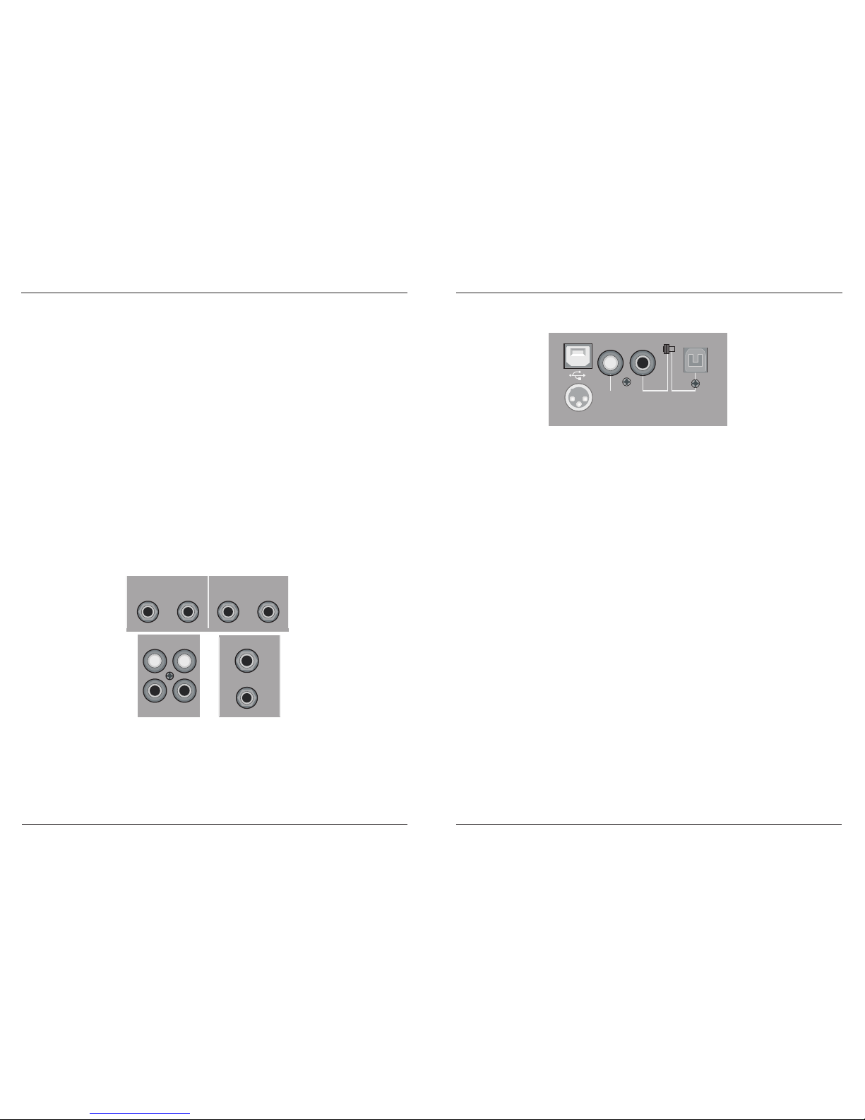
2.6 Rear Panel Section
AC POWER IN
OPTICCOAXIALCOAXIAL
DIGITAL
INPUT
DIGITAL
OUTPUT
12
3
Connect to the assembled power adaptor
AC POWER IN
F ig. 2 . 6 : R e a r P a nel S e ction(with U D )
USB record and playback will work if it is connected with computer
USB SOCKET
To output digital signal when it is recorded, and for digital decode equipment's use
COAXIAL DIGITAL OUTPUT
Connect with DVD or other digital coaxial signal output equipment, for digital signal's coaxial record
COAXIAL DIGITAL INPUT
Optical and coaxial signal record switch over on-off
PUT SWITCH
Connect with DVD or other optical signal output equipment, for digital signal's optical record
OPTICAL INTERFACE
MX-6-FX / MX-8-FX
MX-6-FXU / MX-8-FXU MX-6-FX / MX-8-FX
MX-6-FXU / MX-8-FXU
8
If the c onnec ted effec ts proc es s or receives no input s ignal. the F X S E ND control is probably too
low. T his als o goes for the built-in effects proces s or.
Adjus t y our external effects proces s or to 100% wet (effects s ignal only), before the effec ts s ignal
is added to the main mix along with “ dry” channel s ignals .
In this ins tance, the F X c ontrol of the c hannel being us ed as an effec ts return s hould be turned
fully c ounterc lockwis e. otherwis e feedback problems c an occ ur!
The stereo PHONES connector (at the top of the connector panel) is where you connect headphones.
The unbalanced CTRLROOM OUT connector carry the summed effects and main mix signals, as well
as soloed channel signals.The PHONE/CONTROL ROOM control adjusts the level of both headphones
and main monitor outputs.
The MAIN OUT connectors are unbalanced mono . The main mix signal appears here at a level
of 0 dBu.The MAIN MIX fader adjusts the volume of these outputs. Depending on how you wish to use your
mixer and which gear you own, you can connect the following equipment.
connector
MA I N O U T
P H O N E S /C O N T R O L R O O M O U T
The CD/TAPE INPUTS are used to bring an external signal source (e.g. CD player, tape deck, etc.)
into the console. They can also be used as a standard stereo line input, so the output of a second ME.
C D /TA P E I NP U T
Alternatively the line or tape output of a hi-fi amplifier with source selection switch could also be hooked
up here, allowing you to easily listen to additional sources.
These connectors are laid out RCAconnectors and are wired parallel with the MAIN OUT. Connect the
inputs of a computer sound card or a recorder here. The output signal level is setup using the highly accurate
MAIN MIX fader .
T A P E O U T P U T
Astereo dynamics processor (optional), stereo equalizer (optional) and the stereo power amplifier for
full-range loudspeakers with passive crossovers.
L IV E P A S Y S T E MS :
If you wish to use multi-way loudspeaker systems without an integrated crossovers.Active crossovers
are impiemented directly before the power amplifier, and they divide the frequency range into several
segments that are first amplified in the amplifiers and then passed on to the corresponding
For mastering using a stereo compressor can be recommended. Use it to custom-tailor the dynamic
characteristics of you signal to the dynamic range of the recording equipment you are using. The signal is
in the case passed on from the compressor into the recorder.
R E C O R D IN G
11
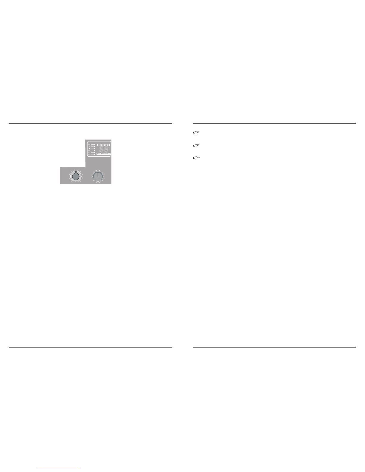
The SIGNALLED on the effects module shows the presence of a signal whose level is high enough. This
LED should always be on. However, make sure that the CLIPLED lights up only sporadically.
If it is constantly, you are overdriving thr effects processor, which leads to unpleasant distortion.
If this occurs, turn the FX controls down somewhat.
S IG N A L a n d C L IP L E D
10 0 F I R S T- C L A S S E F F E C T S
The PROGRAM control has two functions: by turning the PROGRAM control, you dialed the number of
an effect.The number of the preset you just dialed up blinks in the display. To confirm your selection, press
the PROGRAM control; the blinking stops.
P R O G R A M
features a built-in digital stereo effects processor. This effects
processor offers a large number of standard effects such as Hall, Chorus, Flanger, Delay and various
combination effects. Using the FX control, you can feed signals into the effects processor. The integrated
effects module has the advantage of requiring no wiring.This way, the danger of creating ground loops or
uneven signal levels is eliminated at the output, completely simplifying the handing.
The MX-6-FX / MX-8-FX
The FX TO MAIN control feeds the effects signal into the main mix. If the control is turned all the way
counterclockwise, no effects signal is present in the signal of the mixing console.
F X T O M A IN
The appendix contains an overview of all presets of the multi effects processor.
2. 5 D igi ta l e ffe c ts p roc e s s o r
0
- + 15
8
FX SEND S
PROGRAM
(PUSH)
REVERB 00-39
ER/DLY 40-59
MOD 60-73
PITCH 74-79
MULTI 80-99
-3
-6
-10
-15
-20
CLP 24-BITDUALENGINEDSP
24-BITA/D&D/ACONVERTER
88
F ig. 2 . 5 : E ffe cts s e c tion
MX-6-FX / MX-8-FX
MX-6-FXU / MX-8-FXU MX-6-FX / MX-8-FX
MX-6-FXU / MX-8-FXU
9
P O W E R
P leas e do no t c o nne c t mi c ro phon es to th e mix er (o r th e s tage box /wallbo x ) as l ong a s the
pha ntom p ower s u pply in s witc hed on . C o nne c t the mi c ro-P h one s befo re y o u s witc h o n
th e powe r s up ply. IN add ition, the mo nitor/PA lo uds pea k ers s h ou ld be muted befo re y ou
ac ti va te the ph an to m powe r s upply. A fter s w itc h ing o n, wa it appro x . on e minute in orde r
to a llow s y s te m s tabiliza tion.
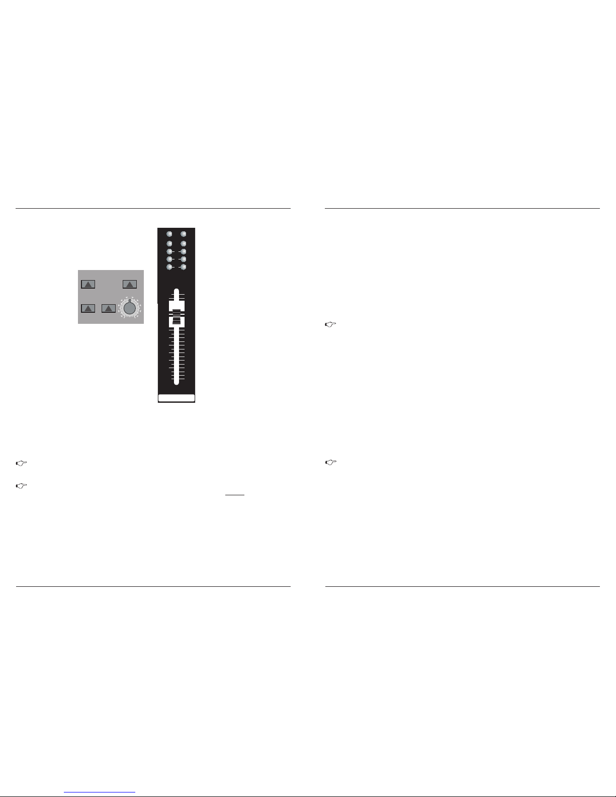
The blue POWER LED indicates that the console in powered on.
L E V E L I N D I C A T O R
The high-precision 4-segment display accurately displays the relevant signal level.
2 . 4 M a i n s e c ti o n
The red +48 V LED lights up when phantom power is turned on. Phantom power is required to operate
condenser microphones and is activates using the +48 V switch located above the +48 V LED.
+48 V
TAPE
TO MIX
TAPE
TO CTRL
FX
TO CTRL
+ 48 V
POWER
0
- + 15
8
L R
20
0
6
CLIP
MAIN MIX
10
0
10
15
20
25
30
40
60
8
PHANTOM
F ig. 2 . 4 : C ontrol e leme nts o f the m ain s e ction
C a ution ! Y ou m us t ne ve r us e u nba lanc e d X L R c on nec to rs ( P IN 1 to 3 c o nn ec te d) on the
MIC inpu t c o nnec to rs if y ou wa nt to u s e th e pha ntom power s u pply.
10
When the TAPE TO MIX switch is depressed, the 2-track input is assigned to the main mix providing
an additional input for tape machines, MIDI instruments or other signal sources that do not require any
processing.
C D/TA P E T O M I X
Press the CD/TAPETO CTRLROOM/PHONESswitch if youwantto monitor the 2-trackinputviathe CTRL
ROOMOUT. Thisprovidesaneasywaytomonitorsignalscomingbackfromtapeto ensurethattheyare
recordingcorrectly.
C D/TA P E T O C T R L
If you are rec ording a s ignal via the C D/TAP E OUTP UT and wis h to lis ten to this s imultaneous ly via
the C D/TA PE INPUT, do not us e the C D/TA PE TO MIX s witch. Doing this would create a feedbac k
loop, s ince the s ignal would be routed, via the main mix, back to tape via the CD/TA PE OUTPUT.
To monitor the CD/TAP E INPUT, us e the C D/TA PE TO C TR L R OOM s witch to as s ign the tape s ignal
to the monitor(s ) or headphones. This will avoid the tape s ignal being routed to the C D/TAPE
OUTPUT.
F X T O C T R L
If you want to monitor only the FX send signal in your headphones or monitor speaker(s), press the
FX TO CTRLswitch. Now the signal of the effects processor can be monitored alone, and the main mix
and/or CD/tape signal is no longer present on the phone and control room outputs.
L E V E L S E T T IN G
To correctly set the gains of the channels, first set the LEVELcontrols of the input channels to their center
positions (0 dB)Then use theTRIM controls to increase the input amplification until signal peaks show 0 dB
on the level meter.
When recording to digital recorders, the recorder s peak meter should not go into overload. While analog
recorders can be overloaded to some extent, creating only a certain amount of distortion (which is common
and often desirable), digital recorders distort quickly when overloaded. In addition, digital distortion is not only
undesirable, but also renders your recording completely useless.
The peak meters of your MX dis play the level virtually independent of frequenc y. A rec ording
level of 0 dB is recommended for all s ignal types .
When recording to an analog device. the VU meters of the recording machine should reach approx. +3 dB
with low-frequency signals (e.g. kick drum). Due to their inertia VU meters tend to display too low a signal level
at frequencies above 1 kHz.This is why, for example, a Hi-Hat should only be driven as far as -10 dB. Since
drums should be driven to approx 0 dB.
MA IN M I X
Use the MAIN MIX fader to adjust the volume of the main out.
P H O N E /C O N T R O L R O O M
Use the PHONE/CONTROLROOM control to adjust the signal level of the CONTROL ROOM and PHONES
outputs.
MX-6-FX / MX-8-FX
MX-6-FXU / MX-8-FXU MX-6-FX / MX-8-FX
MX-6-FXU / MX-8-FXU
This manual suits for next models
3
Table of contents


