gaviota CLIMA 120 User manual
Manual de Instalación
EManuel d’installation
F
Installation Manual
GB Manuale di installazione
I
CLIMA 120

2

3
CLIMA 120
E
• Leer detenidamente estas instrucciones de montaje antes de cualquier uso y conservarlas después de la instalación.
• El no respetar las instrucciones de montaje, uso y especificaciones técnicas del artículo, así como excederse en los rangos de uso
máximos especificados (pesos, etc...), significará la exclusión de la Política de Garantía y de Servicio Postventa de Gaviota Simbac, S.L.
Read carefully these installation instructions before use and keep them after installation.
• Read these assembly instructions carefully before using the equipment and keep them after installation.
• Not respecting the assembly or usage instructions, the product technical specifications or the maximum specified ranges of use (weights, etc.)
will void the Gaviota Simbac, S.L. Warranty and After-Sales Service Policy. Read these installation instructions carefully before use and keep
them after installation.
GB
• Lisez attentivement ces instructions de montage avant toute utilisation et conservez-les après l’installation.
• Le non-respect des instructions de montage, de l’utilisation et des spécifications techniques de l’article, ainsi que le dépassement des plages
maximales d’utilisation spécifiées (poids, etc...), entraîneront l’exclusion de la politique de garantie et de service après-vente de Gaviota Simbac,
S.L. Lisez attentivement ces instructions de montage avant l’utilisation et conservez-les après l’installation.
F
Advertencias de seguridad
E
Safety warnings
FAvertissement de sécurité
GB Avvertence e note di sicurezza
I
• Leggere attentamente queste istruzioni di montaggio prima di qualsiasi utilizzo e conservarle dopo l’installazione.
• Il mancato rispetto delle istruzioni di montaggio, dell’uso e delle specifiche tecniche dell’articolo, nonché il superamento dei campi di utilizzo
massimi specificati (pesi, ecc...), comporterà l’esclusione della garanzia Gaviota Simbac, S.L. e della politica di assistenza post-vendita di Gaviota
Simbac. Leggere attentamente le presenti istruzioni di montaggio prima dell’uso e conservarle dopo l’installazione.
I

4
CLIMA 120
02
Instalación de la estructura • Installing the structure
Installation de la structure • Installazione della struttura
03
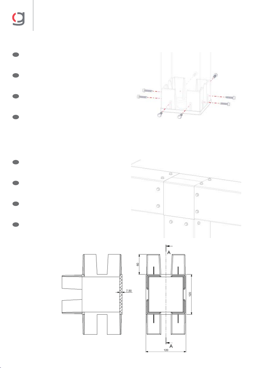
Soporte “T” • T bracket
Support “T” • Supporto “T”
04
Soporte “L” • L bracket
Support “L” • Supporto “L”
05
Juego de soportes articulados • Set of hinged brackets
Ensemble de supports articulés • Set di supporti articolati
06
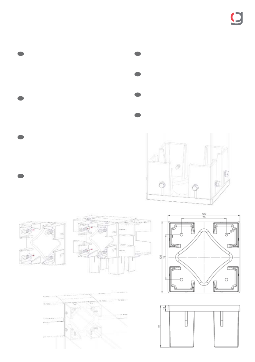
Pie 120x120 • Foot 120x120
Pied 120x120 • Piede 120x120
07
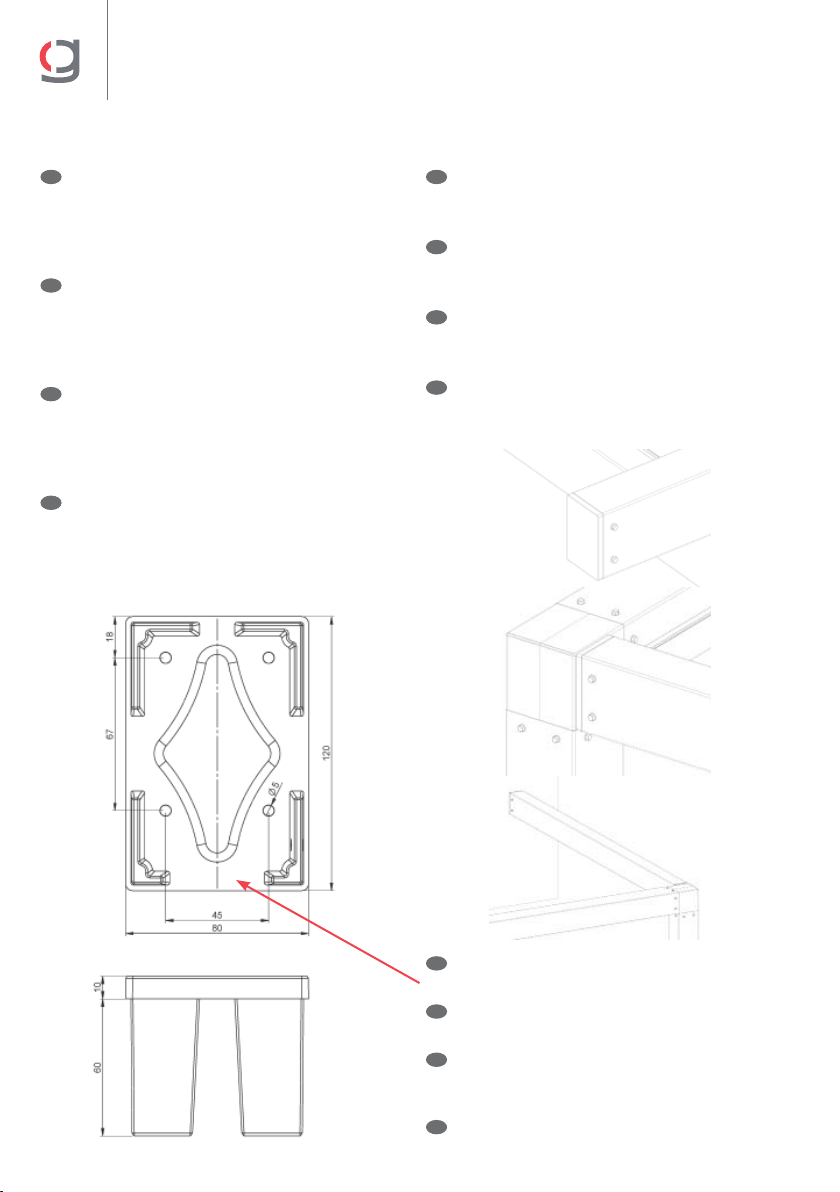
Pie esquinero 120x120 • Corner foot 120x120
Pied d’angle 120x120 • Piede ad angolo 120x120
08
Tapa perfil estructural 120x120 • Structural profile cover 120x120
Couvercle du profil structurel 120x120 • Copertura strutturale del profilo 120x120
09
Tapa perfil estructural 120x80 • Structural profile cover 120x80
Couvercle du profil structurel 120x80 • Copertura strutturale del profilo 120x80
10
Soporte extrusión perfil 120x80 • Extruded profile bracket 120x80
Support extrusion profil 120x80 • Supporto estrusione profilo 120x80
11
Soporte extrusión perfil 120x120 • Extruded profile bracket 120x120
Support extrusion profil 120x120 • Supporto per estrusione profilo 120x120
12
Fijación soportes al perfil regleta • Rail profile fixing brackets
Fixation des supports au profil rail • Montaggio supporti profilo regolino
13
Soportes regulables • Adjustable brackets
Supports réglable • Supporti regolabili
14
Brida pared • Wall bracket
Bride murale • Flangia a parete
15
Brida esquina 120x120 • Corner bracket 120x120
Bride d’angle 120x120 • Flangia ad angolo 120x120
16
Tapa palillo cogida doble led • Cover of double fabric profile LED
Couvercle du porte-toile double led • Tappo di profilo tessutto doppio LED
17
Confección de lona palillo led • Fabric preparation with LED profile
Confection de toile profil led • Confezione tela profilo LED
Índice • Index • Index • Indice
Listado de componentes • List of components
Liste des composants • Elenco dei componenti
01

5
CLIMA 120
N°
Código
Code • Code
Codice
Artículo • Item • Article • Articolo
1 80141850 Guía 120x80 Clima 120 blanco 5m •
Guide 120x80 Clima 120 white 5m
Guide 120x80 Clima 120 blanc 5m • Guida 120x80 Clima 120 bianco 5m
2 80141862 Guía 120x80 Clima 120 blanco 6m •
Guide 120x80 Clima 120 white 6m
Guide 120x80 Clima 120 blanc 6m • Guida 120x80 Clima 120 bianco 6m
3 80141874 Guía 120x80 Clima 120 blanco 7m •
Guide 120x80 Clima 120 white 7m
Guide 120x80 Clima 120 blanc 7m • Guida 120x80 Clima 120 bianco 7m
4 80141886 Estructura 120x120 Clima 120 5m •
Structure 120x120 Clima 120 5m
Structure 120x120 Clima 120 5m • Struttura 120x120 Clima 120 5 m
5 80141898 Estructura 120x120 Clima 120 6m •
Structure 120x120 Clima 120 6m
Structure 120x120 Clima 120 6m • Struttura 120x120 Clima 120 6m
6 80141910 Estructura 120x120 Clima 120 7m •
Structure 120x120 Clima 120 7m
Structure 120x120 Clima 120 7m • Struttura 120x120 Clima 120 7m
7 80141922 Estructura para regleta 120x120 Clima 120 5m •
Structure for rail 120x120 Clima 120 5m
Structure pour rail 120x120 Clima 120 5m • Struttura per regolino 120x120 Clima 120 5m
8 80141934 Estructura para regleta 120x120 Clima 120 6m •
Structure for rail 120x120 Clima 120 6m
Structure pour rail 120x120 Clima 120 6m • Struttura per regolino 120x120 Clima 120 6m
9 80141946 Estructura para regleta 120x120 Clima 120 7m •
Structure for rail 120x120 Clima 120 7m
Structure pour rail 120x120 Clima 120 7m • Struttura per regolino 120x120 Clima 120 7m
10 80141958 Estructura 120x80 Clima 120 5m •
Structure 120x80 Clima 120 5m
Structure 120x80 Clima 120 5m • Struttura 120x80 Clima 120 5m
11 80141970 Estructura 120x80 Clima 120 6m •
Structure 120x80 Clima 120 6m
Structure 120x80 Clima 120 6m • Struttura 120x80 Clima 120 6m
12 80141982 Estructura 120x80 Clima 120 7m •
Structure 120x80 Clima 120 7m
Structure 120x80 Clima 120 7m • Struttura 120x80 Clima 120 7m
13 80141994 Soporte “T” Clima 120 blanco •
T bracket Clima 120 white
Support “T” Clima 120 blanc • Supporto “T” Clima 120 bianco
14 80142006 Soporte “L” Clima 120 blanco •
L bracket Clima 120 white
Support “L” Clima 120 blanc • Supporto “L” Clima 120 bianco
15 80142018 Soportes articulados Clima 120 blanco •
Hinged brackets Clima 120 white
Supports articulés Clima 120 blanc • Supporti snodati Clima 120 bianco
16 80142030 Pie 120x120 Clima 120 blanco •
120x120 foot Clima 120 white
Pied 120x120 Clima 120 blanc • Piede 120x120 Clima 120 bianco
17 80142042 Pie esquinero 120x120 Clima 120 blanco •
120x120 corner foot Clima 120 white
Pied d’angle 120x120 Clima 120 blanc • Piede ad angolo 120x120 Clima 120 bianco
18 80142054 Tapa perfil estructura 120x120 Clima 120 blanco •
120x120 profile structure cover Clima 120 white
Couvercle profil structure 120x120 Clima 120 blanc • Tappo profilo struttura 120x120 Clima 120 bianco
19 80142066 Tapa perfil estructura 120x80 Clima 120 blanco •
120x80 profile structure cover Clima 120 white
Couvercle profil structure 120x80 Clima 120 blanc • Tappo profilo struttura 120x80 Clima 120 bianco
20 80142078 Soportes estrusión perfil 120x80 Clima 120 blanco •
Extruded profile brackets 120x80 Clima 120 white
Supports extrusion profil 120x80 Clima 120 blanco • Supporti estrusione profilo 120x80 Clima 120 bianco
21 80142252 Soportes estrusión perfil 120x120 Clima 120 blanco •
Extruded profile brackets 120x120 Clima 120 blanco
Supports extrusion profil 120x120 Clima 120 blanco • Supporti estrusione profilo 120x120 Clima 120 bianco
22 80142090 Conjunto bolsa regleta rombo Clima 120 •
Bag of rhombus rails Clima 120
Ensemble sachets rail losange Clima 120 • Set sacchetto regolino rombo Clima 120
23 80142422 Guía 120x120 Clima 120 blanco 7m •
Guide 120x120 Clima 120 white 7m
Guíde 120x120 Clima 120 blanc 7m • Guida 120x120 Clima 120 bianco 7m
24 80142510 Palillo doble Led Clima 120 blanco 7m •
Double LED handle Clima 120 white 7m
Profil double Led Clima 120 blanc 7m • doppio LED Clima 120 bianco 7m
25 80142433 Kit soporte regulable 120x80 Clima 120 blanco •
120x80 adjustable bracket kit Clima 120 white
Kit de support réglable 120x80 Clima 120 blanc • Kit supporto regolabile 120x80 Clima 120 bianco
26 80142444 Kit soporte regulable 120x120 Clima 120 blanco •
120x120 adjustable bracket kit Clima 120 white
Kit de support réglable 120x120 Clima 120 blanc • Kit supporto regolabile 120x120 Clima 120 bianco
27 80142455 Brida pared 120x120 Clima 120 blanco •
120x120 wall bracket Clima 120 white
Bride murale 120x120 Clima 120 blanc • Flangia a parete 120x120 Clima 120 bianco
28 80142466 Brida esquina 120x120 Clima 120 blanco •
120x120 corner bracket Clima 120 white
Bride murale 120x120 Clima 120 blanc • Flangia ad angolo 120x120 Clima 120 bianco
29 80142477 Tapa palillo doble Led Clima 120 blanco •
Double LED handle cover Clima 120 white
Couvercle profil double Led Clima 120 blanc • Tappo profilo doppio LED Clima 120 bianco
Listado de componentes • List of components
Liste des composants • Elenco dei componenti
01
6
CLIMA 120
Instalación de la estructura • Installing the structure
Installation de la structure • Installazione della struttura
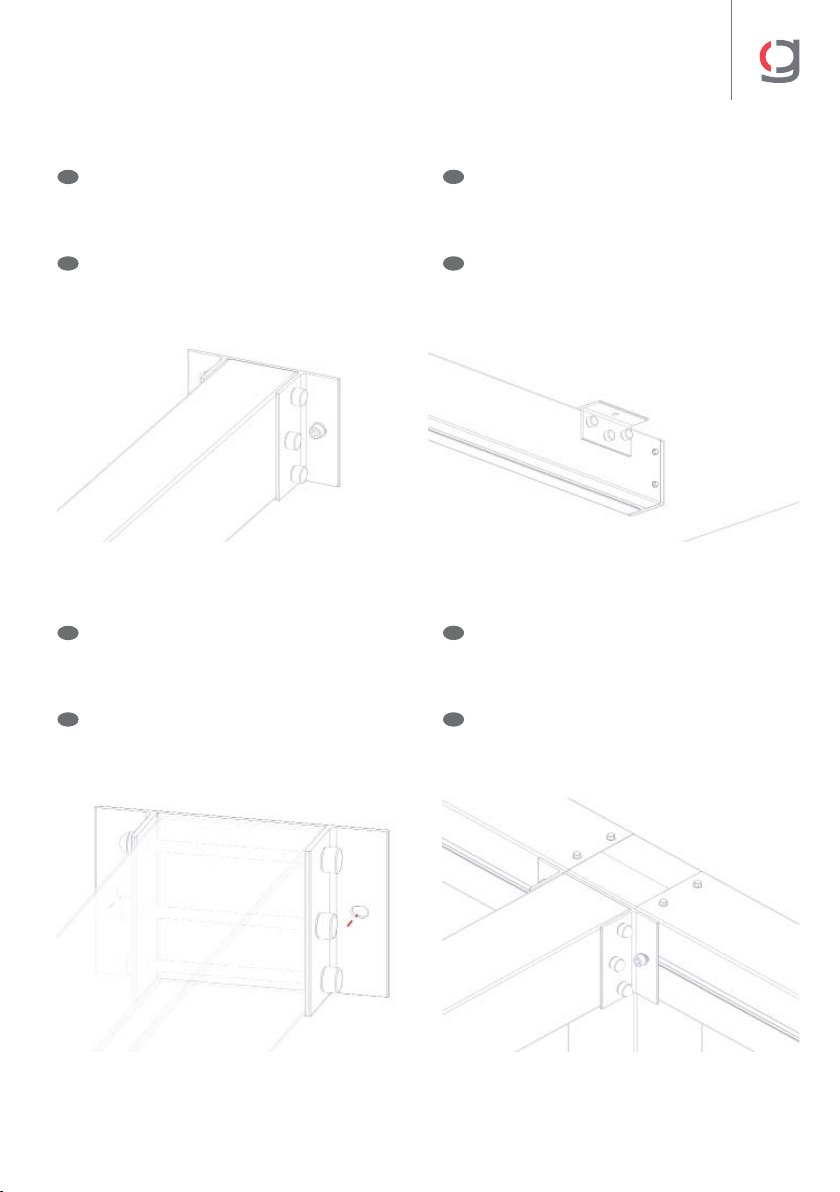
02
Soporte “T” • T bracket
Support “T” • Supporto “T”
03
NOTA: Se recomienda usar tornillos roscachapa
para la unión de las piezas a los perfiles: Tornillo
Ø5,5x22 DIN7504-K.
E
NOTA: Se recomienda usar tornillos roscachapa
para la unión de las piezas a los perfiles: Tornillo
Ø5,5x22 DIN7504-K.
E
NOTE: We recommend using threaded screws to
connect the parts to the profiles: Screw Ø5.5x22
DIN7504-K.
GB
NOTE: We recommend using threaded screws to
connect the parts to the profiles: Screw Ø5.5x22
DIN7504-K.
GB
NOTE : Il est recommandé d’utiliser des vis
autoperceuses pour le raccordement des pièces
aux profils : Vis Ø5,5x22 DIN7504-K.
F
NOTE : Il est recommandé d’utiliser des vis
autoperceuses pour le raccordement des pièces
aux profils : Vis Ø5,5x22 DIN7504-K.
F
NOTA: si consiglia di utilizzare viti filettate per
il collegamento dei pezzi ai profili: Vite Ø5,5x22
DIN7504-K.
I
NOTA: si consiglia di utilizzare viti filettate per
il collegamento dei pezzi ai profili: Vite Ø5,5x22
DIN7504-K.
I

7
CLIMA 120
Soporte “L” • L bracket
Support “L” • Supporto “L”
04
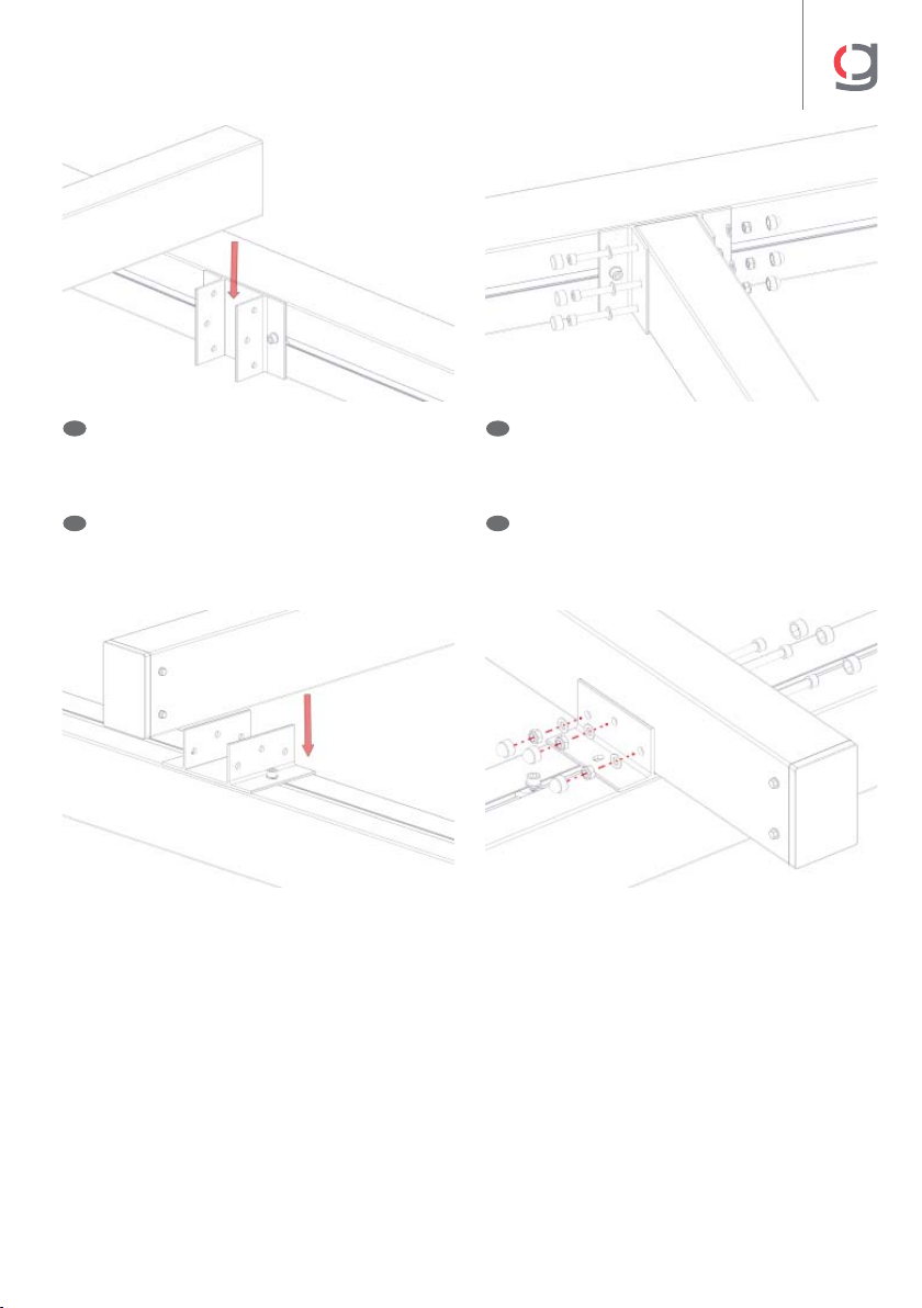
Juego de soportes articulados • Set of hinged brackets
Ensemble de supports articulés • Set di supporti articolati
05
NOTA: Se recomienda usar tornillos roscachapa
para la unión de las piezas a los perfiles: Tornillo
Ø5,5x22 DIN7504-K.
E
NOTE: We recommend using threaded screws to
connect the parts to the profiles: Screw Ø5.5x22
DIN7504-K.
GB
NOTE : Il est recommandé d’utiliser des vis
autoperceuses pour le raccordement des pièces
aux profils : Vis Ø5,5x22 DIN7504-K.
F
NOTA: si consiglia di utilizzare viti filettate per
il collegamento dei pezzi ai profili: Vite Ø5,5x22
DIN7504-K.
I
NOTA: Se recomienda usar tornillos roscachapa
para la unión de las piezas a los perfiles: Tornillo
Ø5,5x22 DIN7504-K.
Por la parte de la articulación, utilizar el tornillo
proporcionado de M8x150 DIN 912 DACRO.
E
NOTE: We recommend using threaded screws to
connect the parts to the profiles: Screw Ø5.5x22
DIN7504-K.
For the joint side, use the M8x150 DIN 912 DACRO
screw provided.
GB
NOTE : Il est recommandé d’utiliser des vis
autoperceuses pour le raccordement des pièces
aux profils : Vis Ø5,5x22 DIN7504-K.
Pour la partie de l’articulation, utilisez la vis fournie
de M8x150 DIN 912 DACRO.
F
NOTA: si consiglia di utilizzare viti filettate per
il collegamento dei pezzi ai profili: Vite Ø5,5x22
DIN7504-K.
Per il lato giunto, utilizzare la vite fornita M8x150
DIN 912 DACRO.
I

8
CLIMA 120
Pie 120x120 • Foot 120x120
Pied 120x120 • Piede 120x120
06
Pie esquinero 120x120 • Corner foot 120x120
Pied d’angle 120x120 • Piede ad angolo 120x120
07
NOTA: Se recomienda usar tornillos roscachapa
para la unión de las piezas a los perfiles: Tornillo
Ø5,5x22 DIN7504-K.
E
NOTE: We recommend using threaded screws to
connect the parts to the profiles: Screw Ø5.5x22
DIN7504-K.
GB
NOTE : Il est recommandé d’utiliser des vis
autoperceuses pour le raccordement des pièces
aux profils : Vis Ø5,5x22 DIN7504-K.
F
NOTA: si consiglia di utilizzare viti filettate per
il collegamento dei pezzi ai profili: Vite Ø5,5x22
DIN7504-K.
I
Esta pieza se puede utilizar para poner screen
o cortavientos permitiendo que los sistemas
lleguen al suelo.
ENOTA: Se recomienda usar tornillos roscachapa
para la unión de las piezas a los perfiles: Tornillo
Ø5,5x22 DIN7504-K.
E
This part can be used to mount a screen or
windbreak, allowing the systems to reach the
ground.
GB NOTE: We recommend using threaded screws to
connect the parts to the profiles: Screw Ø5.5x22
DIN7504-K.
GB
Cette pièce peut être utilisée pour mettre un
screen ou un coupe-vent permettant aux systèmes
d’atteindre le sol.
FNOTE : Il est recommandé d’utiliser des vis
autoperceuses pour le raccordement des pièces
aux profils : Vis Ø5,5x22 DIN7504-K.
F
Questo pezzo può essere usato per inserire uno
screen o un frangivento che permetta ai sistemi di
arrivare a terra.
INOTA: si consiglia di utilizzare viti filettate per
il collegamento dei pezzi ai profili: Vite Ø5,5x22
DIN7504-K.
I
9
CLIMA 120
Tapa perfil estructural 120x120 • Structural profile cover 120x120
Couvercle du profil structurel 120x120 • Copertura strutturale del profilo 120x120
08
Esta pieza se puede usar para fijar la estructura
al suelo o a la pared; así como para unir otras
piezas.
Taladrar la pieza por los agujeros marcados en
el interior a Ø9. Utilizar unos tornillos de M8; así
como tuercas autoblocantes si se desea unir
varias piezas.
E
This part can be used to fix the structure to the floor
or the wall, as well as to join other pieces together.
Drill the part through the holes marked inside at
Ø9. Use M8 screws and self-locking nuts if several
parts need to be joined.
GB
Cette pièce peut être utilisée pour fixer la structure
au sol ou au mur, ainsi que pour assembler
d’autres pièces.
Percez la pièce à travers les trous marqués à l’intérieur
à Ø9. Utilisez des vis M8 et des écrous autobloquants si
plusieurs pièces doivent être assemblées.
F
Questo pezzo può essere utilizzato per fissare la
struttura al pavimento o alla parete, così come per
unire altri pezzi. Trapana il pezzo attraverso i fori
segnati all’interno di Ø9. Se si devono unire più
pezzi, utilizzare viti M8 e dadi autobloccanti.
I
NOTA: Se recomienda usar tornillos roscachapa
para la unión de las piezas a los perfiles: Tornillo
Ø5,5x22 DIN7504-K.
E
NOTE: We recommend using threaded screws to
connect the parts to the profiles: Screw Ø5.5x22
DIN7504-K.
GB
NOTE : Il est recommandé d’utiliser des vis
autoperceuses pour le raccordement des pièces
aux profils : Vis Ø5,5x22 DIN7504-K.
F
NOTA: si consiglia di utilizzare viti filettate per
il collegamento dei pezzi ai profili: Vite Ø5,5x22
DIN7504-K.
I
10
CLIMA 120
Tapa perfil estructural 120x80 • Structural profile cover 120x80
Couvercle du profil structurel 120x80 • Tappo profilo strutturale 120x80
09
Esta pieza se puede usar para fijar la estructura
a la pared; así como para unir otras piezas.
Taladrar la pieza por los agujeros marcados en
el interior a Ø9. Utilizar unos tornillos de M8 con
tuercas autoblocantes.
E
This part can be used to fix the structure to the
wall, as well as to join other pieces together.
Drill the part through the holes marked inside at
Ø9. Use M8 screws with self-locking nuts.
GB
Cette pièce peut être utilisée pour fixer la structure
au mur, ainsi que pour assembler d’autres pièces.
Percez la pièce à travers les trous marqués à
l’intérieur à Ø9. Utilisez des vis M8 avec des écrous
autobloquants.
F
Questo pezzo può essere utilizzato per fissare la
struttura alla parete o per unire altri pezzi.
Trapana il pezzo attraverso i fori segnati all’interno
di Ø9. Utilizzare viti M8 con dadi autobloccanti.
I
NOTA: Se recomienda usar tornillos roscachapa
para la unión de las piezas a los perfiles: Tornillo
Ø5,5x22 DIN7504-K.
E
NOTE: We recommend using threaded screws to
connect the parts to the profiles: Screw Ø5.5x22
DIN7504-K.
GB
NOTE : Il est recommandé d’utiliser des vis
autoperceuses pour le raccordement des pièces
aux profils : Vis Ø5,5x22 DIN7504-K.
F
NOTA: si consiglia di utilizzare viti filettate per
il collegamento dei pezzi ai profili: Vite Ø5,5x22
DIN7504-K.
I
NOTA: la pieza tiene posición para encajar en el
perfil guía (abertura grande hacia abajo).
E
NOTE: the part is positioned to fit the guide rail
(large opening downwards).
GB
NOTE : la pièce est positionnée de manière à
s’emboîter au profil guide (grande ouverture vers
le bas).
F
NOTA: il pezzo è posizionato in modo da adattarsi
alla guida (apertura grande verso il basso).
I
11
CLIMA 120
Soporte extrusión perfil 120x80 • Extruded profile bracket 120x80
Support extrusion profil 120x80 • TSoporte extrusión perfil 120x80
10
NOTA: Usar los tornillos proporcionados M8x100
DIN912 para fijar el perfil a la pieza. Para la
sujeción de la pieza a la pared o techo, utilizar
tornillos apropiados según ésta.
NOTE: Use the M8x100 DIN912 screws provided to
fix the profile to the part. Use appropriate screws
for wall or ceiling mounting.
NOTE : Utilisez les vis M8x100 DIN912 fournies pour
fixer le profil à la pièce. Utilisez des vis appropriées
pour la fixation de la pièce au mur ou au plafond.
NOTA: Utilizzare le viti M8x100 DIN912 in dotazione
per fissare il profilo al pezzo. Utilizzare viti
appropriate per il montaggio a parete o a sotto.
A pared
To wall
Au mur
A parete
A techo
To ceiling
Au plafond
A sotto
Soporte extrusión perfil 120x120 • Extruded profile bracket 120x120 Support
extrusion profil 120x120 • Supporto estrusione profilo 120x120
11
A pared o techo
Mounted to wall or ceiling
Au mur ou au plafond
A parete o sotto
Al perfil regleta
Fixed to the rail profile
Au profil rail
Al profilo regolino
E
GB
F
I
NOTA: Usar los tornillos proporcionados M8x140
DIN912 para fijar el perfil a la pieza. Para la
sujeción de la pieza a la pared o techo, utilizar
tornillos apropiados según ésta.
E
NOTE: Use the M8x140 DIN912 screws provided to
fix the profile to the part. Use appropriate screws
for wall or ceiling mounting.
GB
NOTE : Utilisez les vis M8x140 DIN912 fournies pour
fixer le profil à la pièce. Utilisez des vis appropriées
pour la fixation de la pièce au mur ou au plafond.
F
NOTA: Utilizzare le viti M8x140 DIN912 in dotazione
per fissare il profilo al pezzo. Utilizzare viti
appropriate per il montaggio a parete o a sotto.
I

12
CLIMA 120
Fijación soportes al perfil regleta • Rail profile fixing brackets
Fixation des supports au profil rail • Supporti di montaggio al profilo regolino
12
NOTA: la regleta hay que introducirla con las
caras largas del rombo de manera paralela a
la ranura del perfil. Girarlas en sentido horario
hasta que los lado cortos del rombo queden pa-
ralelos a la ranura del perfil. Este paso es muy
importante, pues una incorrecta instalación
de las regletas haría que el sistema estuviese
fuera de homologación.
E
NOTE: the rail should be inserted so that the long
edges of the rhombus are parallel with the profile
groove. Turn them clockwise until the short edges
of the rhombus are parallel with the profile groove.
This step is very important, because if the rails
are installed incorrectly the system will not be
approved for use.
GB
NOTE : le rail doit être inséré avec les côtés
longs du losange parallèles à la rainure du profil.
Tournez-les dans le sens des aiguilles d’une
montre jusqu’à ce que les côtés courts du losange
soient parallèles à la rainure du profil. Cette étape
est très importante, car une installation incorrecte
des rails rendrait le système non homologué.
F
NOTA: il regolino deve essere inserito con i lati
lunghi del rombo paralleli alla scanalatura del
profilo. Ruotarli in senso orario fino a quando i lati
corti del rombo non sono paralleli alla scanalatura
del profilo. Questo passaggio è molto importante,
perché un’errata installazione dei regolini
renderebbe il sistema non omologato.
I
Usar los tornillos proporcionados en la bolsa
regleta rombo M6x16 DIN912 INOX para fijar la
pieza al perfil.
E
Use the screws provided in the M6x16 DIN912 INOX
rhombus rail bag to fix the part to the profile.
GB
Utilisez les vis fournies dans le sachet rail losange
M6x16 DIN912 INOX pour fixer la pièce au profil.
F
Per fissare il pezzo al profilo, utilizzare le viti
fornite in dotazione nel sacchetto regolino a rombo
M6x16 DIN912 INOX.
I
13
CLIMA 120
NOTA: Según la posición del perfil estructural
regleta 120x120 las guías pueden ir a la misma
altura que éste (imágenes superiores) o por
encima (imágenes inferiores).
E
NOTE: Depending on the position of the 120x120
structural profile rail, the guides may be at the
same height as it (upper pictures) or above it
(lower pictures).
GB
NOTE : Selon la position du profil structurel du
rail 120x120, les guides peuvent être à la même
hauteur que celle-ci (photos du haut) ou au-dessus
de celle-ci (photos du bas).
F
NOTA: A seconda della posizione del profilo
strutturale del regolino 120x120, le guide possono
trovarsi alla sua stessa altezza (immagini
superiori) o sopra di essa (immagini inferiori).
I

14
CLIMA 120
Soportes regulables • Adjustable brackets
Supports réglable • Supporti regolabili
13
Unir la articulación al soporte mediante tornillos
M8x100 DIN912 DACRO, utilizando tuercas
autoblocantes M8 DIN985 y las arandelas M8
DIN125.
E
Acoplar a la articulación el soporte (120x120
ó 120x80) mediante tornillos M8x130 DIN912
DACRO, utilizando tuercas autoblocantes M8
DIN985 y las arandelas M8 DIN125.
E
NOTA: apretar el tornillo con la inclinación
deseada.
E
NOTA: apretar el tornillo con la inclinación
deseada.
E
Fix the joint to the bracket using M8x100 DIN912
DACRO screws, M8 DIN985 self-locking nuts and
M8 DIN125 washers.
GB
Fix the joint to the bracket (120x120 or 120x80)
using M8x130 DIN912 DACRO screws, M8 DIN985
self-locking nuts and M8 DIN125 washers.
GB
NOTE: tighten the screw to the desired angle.
GB
NOTE: tighten the screw to the desired angle.
GB
Assemblez l’articulation au support à l’aide de vis
M8x100 DIN912 DACRO, en utilisant des écrous
autobloquants M8 DIN985 et des rondelles M8
DIN125.
F
Fixez le support (120x120 ou 120x80) à
l’articulation à l’aide de vis DACRO M8x130 DIN912,
d’écrous autobloquants M8 DIN985 et de rondelles
M8 DIN125.
F
NOTE : serrez la vis avec l’inclinaison souhaitée.
F
NOTE : serrez la vis avec l’inclinaison souhaitée.
F
Fissare il giunto al supporto con viti M8x100
DIN912 DACRO utilizzando dadi autobloccanti M8
DIN985 e rondelle M8 DIN125.
I
Fissare il giunto al supporto (120x120 o 120x80)
mediante viti M8x130 DIN912 DACRO utilizzando
dadi autobloccanti M8 DIN985 e rondelle M8
DIN125.
I
NOTA: serrare la vite con l’inclinazione desiderata.
I
NOTA: serrare la vite con l’inclinazione desiderata.w
I

15
CLIMA 120
NOTA: Se recomienda usar tornillos roscachapa
para la unión de las piezas a los perfiles: tornillo
Ø5,5x22 DIN7504-K.
E
Nota importante: el máximo de soportes
recomendados para un sistema es de 2
unidades. Siempre en montajes pared-portería
o entre paredes.
E
NOTE: We recommend using threaded screws to
connect the parts to the profiles: screw Ø5.5x22
DIN7504-K.
GB
Important note: the maximum recommended
number of brackets for a system is 2. This is
always the case for wall-frame and wall-wall
installations.
GB
NOTE : Il est recommandé d’utiliser des vis
autoperceuses pour l’assemblage des pièces aux
profils : vis Ø5,5x22 DIN7504-K.
F
NOTE importante : le nombre maximum
recommandé de supports pour un système est
de 2 unités. Toujours en montage mur-entrée ou
entre deux murs.
F
NOTA: Si consiglia di utilizzare viti filettate per
il collegamento dei pezzi ai profili: vite Ø5,5x22
DIN7504-K.
I
Nota importante: il numero massimo consigliato
di supporti per un sistema è 2 unità. Sempre in
montaggi a parete/porta o tra pareti.
I
Brida pared • Wall bracket
Bride murale • Flangia a parete
14
NOTA: marcar los agujeros en la pared y taladrar.
Fijar las bridas con los tornillos correctos,
según la superficie de instalación.
E
NOTE: mark the holes on the wall before drilling
them. Fix the brackets with the appropriate screws,
according to the installation surface.
GB
NOTE : marquez les trous sur le mur et percez.
Fixez les brides avec les bonnes vis, en fonction de
la surface d’installation.
F
NOTA: segnare i fori sulla parete e trapanare.
Fissare le flange con le viti corrette, a seconda
della superficie di installazione.
I
Ø8,5 Ø8,5
16
CLIMA 120
Brida esquina 120x120 • Corner bracket 120x120
Bride d’angle 120x120 • Flangia ad angolo 120x120
15
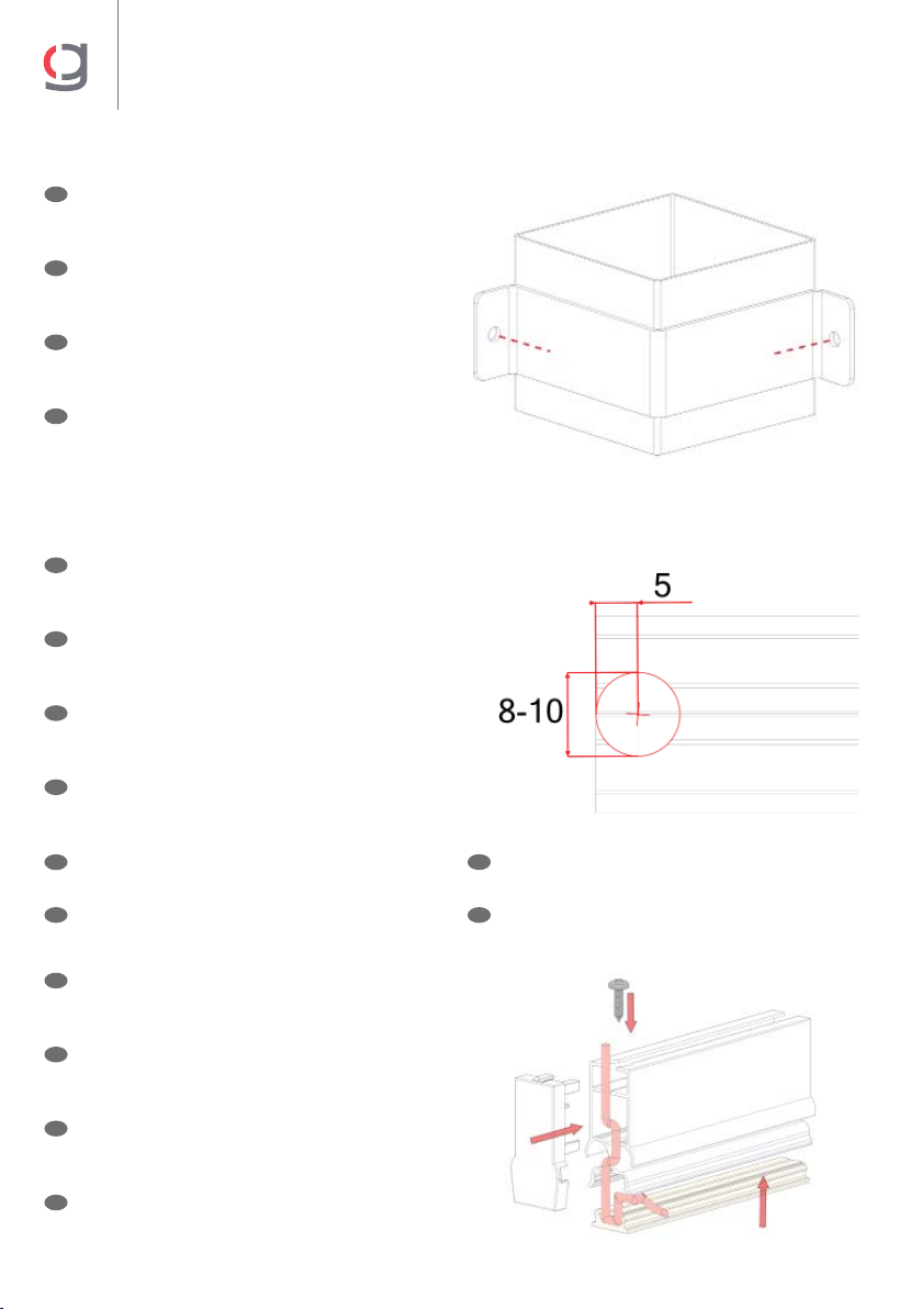
Tapa palillo cogida doble led • Cover of double fabric profile LED
Couvercle du porte-toile double led • Tappo di profilo tessutto doppio LED
16
Mecanizar en los extremos del palillo un agujero
en la parte superior de Ø8 ó Ø10mm; a 5mm del
extremo.
E
Machine a hole at the top of the fabric profile of 8 to
10 mm in diameter, 5mm from the end.
GB
Percez un trou aux extrémités du profil sur la
partie supérieure, de Ø8 ou Ø10mm, à 5mm de
l’extrémité.
F
Praticare un foro nella parte superiore del profilo
di Ø8 o Ø10 mm; a 5 mm dall’estremità.
I
NOTA: mecanizar únicamente la apertura
superior.
E
NOTE: only machine the top opening.
GB
NOTE : n’usinez que l’ouverture supérieure.
F
NOTA: operare solo sull’apertura superiore.
I
NOTA: Se recomienda usar tornillos roscachapa
para la unión de la tapa al perfil: tornillo Ø3,5x13
DIN7504-N.
E
NOTE: We recommend using threaded screws to
connect the cover to the profile: screw Ø3.5x13
DIN7504-N.
GB
NOTE : Il est recommandé d’utiliser des vis
autoperceuses pour l’assemblage de l’Couvercle
au profil : vis Ø3,5x13 DIN7504-N.
F
NOTA: Si consiglia di utilizzare viti filettate per
la giunzione del tappo al profilo: vite Ø3,5x13
DIN7504-N.
I
NOTA: marcar los agujeros en la pared y taladrar.
Fijar las bridas con los tornillos correctos,
según la superficie de instalación.
E
NOTE: mark the holes on the wall before drilling
them. Fix the brackets with the appropriate screws,
according to the installation surface.
GB
NOTE : marquez les trous sur le mur et percez.
Fixez les brides avec les bonnes vis, en fonction de
la surface d’installation.
F
NOTA: segnare i fori sulla parete e trapanare.
Fissare le flange con le viti corrette, a seconda
della superficie di installazione.
I
Ø8,5 Ø8,5
17
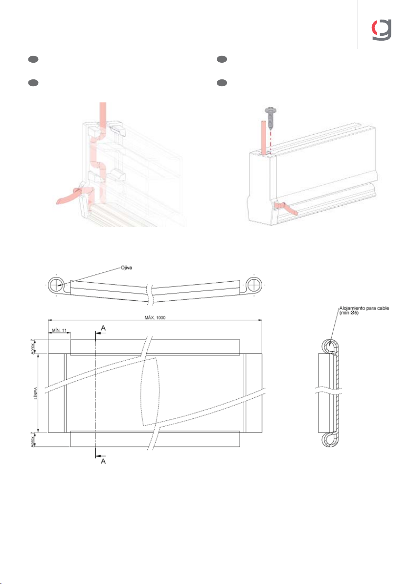
CLIMA 120
El cable de los leds tiene que salir o bien por
la parte superior de la tapa; o por los laterales.
E
The LED cable should come out either from the top
of the cover or from the sides.
GB
Le câble des leds doit sortir soit par le haut de
l’Couvercle, soit par les côtés.
F
Il cavo dei LED deve uscire o dalla parte superiore
del tappo o dai lati.
I
Confección de lona palillo led • Fabric preparation with LED profile
Confection de toile profil led • Confezione tela profilo LED
17

18

19

GAVIOTA
Autovía de Alicante, A-31 Km.196
03630 Sax (Alicante) - España / Spain
Tel. +34 965 474 200•Fax +34 965 475 680
International Dept: +34 966 968 276•Fax +34 966 968 075
www.gaviotasimbac.com
REF. 4004 0701 • GAVIOTA • 10-2020 © COPYRIGHT RESERVED
Table of contents
Other gaviota Outdoor Furnishing manuals

Popular Outdoor Furnishing manuals by other brands

Milkcan
Milkcan Square Vertical Garden quick start guide

Barton
Barton 96187 Owner's manual and safety instructions

BCP
BCP SKY3344 instruction manual

Master Garden
Master Garden Bamboo North Arbor BNA-72 Assembly guide

Verano
Verano V762 TALAMANCA installation manual

LAZBOY
LAZBOY Sears Scarlett D71 M 20946 Use and care guide


Premium Poly Patios
Premium Poly Patios Luxcraft Crestville Classic CV-5CPG quick start guide

Salvatori
Salvatori SPAN manual

Outsunny
Outsunny 84C-204 Assembly instruction

Sunjoy
Sunjoy D-GG001PST-F1 Assembly instruction

Uberhaus
Uberhaus 38115134 Operator's manual

Gudrum
Gudrum GLOUCESTER PERGOLA SEAT GJA10218 Assembly instructions