GBS Elettronica LCD-104 User manual

Part 1a - Install the Wall Piece (Drywall)
Part 1b - Install the Wall Piece (Concrete)
1.Using a high quality stud finder,locate and mark one stud for installing the wall mount.
Use a small nail or awl to verify the location of the stud.
2.Place the wall piece portion of the mount over the center of the marked stud and level
it using the integrated bubble guide.
3.Mark off the two holes for securing the mount and place the wall piece aside.
4.Using an electric or portable drill with 1/8”(3 mm) bit,drill the marked holes.
5.Move the wall piece portion of the mount back into place and attach itusing the
Drywall Screws (A) from the hardware kit.Make sure both screws are snug,but do not
to over-tighten them.
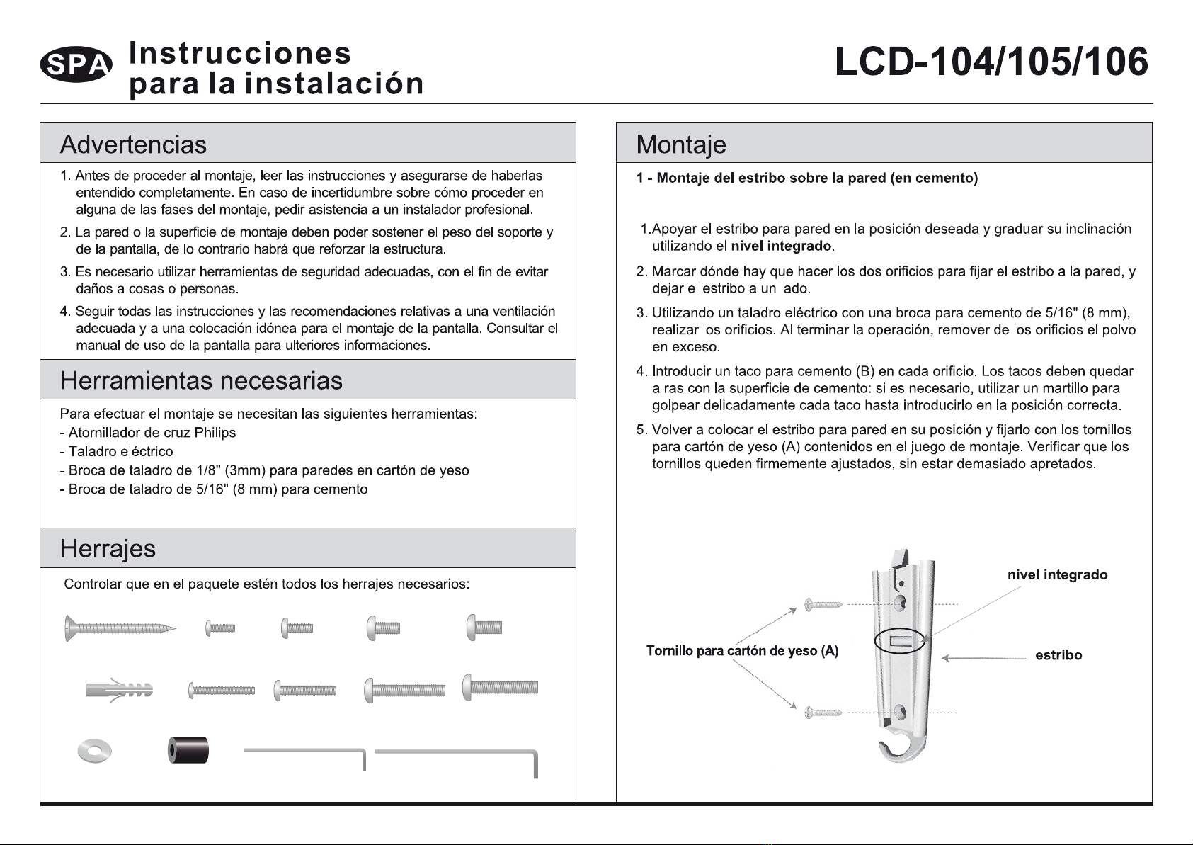
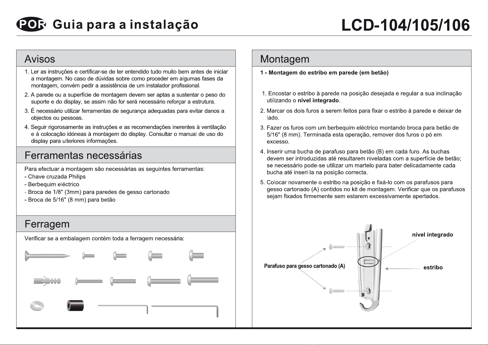
Check to make sure all hardware has been includedwith your mount. You should find
the following:
1.Place the wall piece portion of the mount inthe desired location and level it using the
integrated bubble guide.
2.Mark off the two holes for securing the mount and place the wall piece aside.
3.Using an electric or portable drill with 5/16”(8 mm) masonry bit,drill the marked holes.
After drilling,remove any excessdust from the holes.
4.Insert a Concrete Anchor (B) into each hole.The anchors must be inserted until they are
flush with the concrete surface;a hammer can be used to lightly tap each anchor into
place if necessary.
5. Move the wall piece portion of the mount back into place and attach it using the
Drywall Screws (A) from the hardware kit.Make sure both screws are snug,but do not
to over-tighten them.
Drywall Screws (A)Wall Piece
(A) Drywall Screw x2 (C) M4 x 12 x4 (E) M5 x 12 x4
(F) M5 x 25 x4
(G) M6 x 12 x4 (I) M8 x 12 x4
(J) M8 x 25 x4(D) M4 x 25 x4 (H) M6 x 25 x4(B) x2
(M) 3 mm x1 (N) 4 mm x1
(K) M6 x4 (L) 10mm x4
1. Make sure these instructions are read and completelyunderstood before attempting
installation.If you are unsure of any part of this installation,contact aprofessional
installer for assistance.
2. The wall or mounting surface must be capable of supporting the combined weight of
the mount and the display;otherwise the structure must be reinforced.
3. Safety gear and proper tools must be used. Failure to do so can result in damage or
injury.
4. Follow all instructions and recommendations regarding adequate ventilation and
suitable locations for mounting your display. Consult the owner’s manual for your
display for more information.
You will need the following tools to complete your installation:
• Phillips Head Screw Driver
• Electric or Portable Drill
• Stud Finder and 1/8”(3 mm) Drill Bit for Drywall Installation
• 5/16”(8 mm) Masonry Bit for Concrete Installation

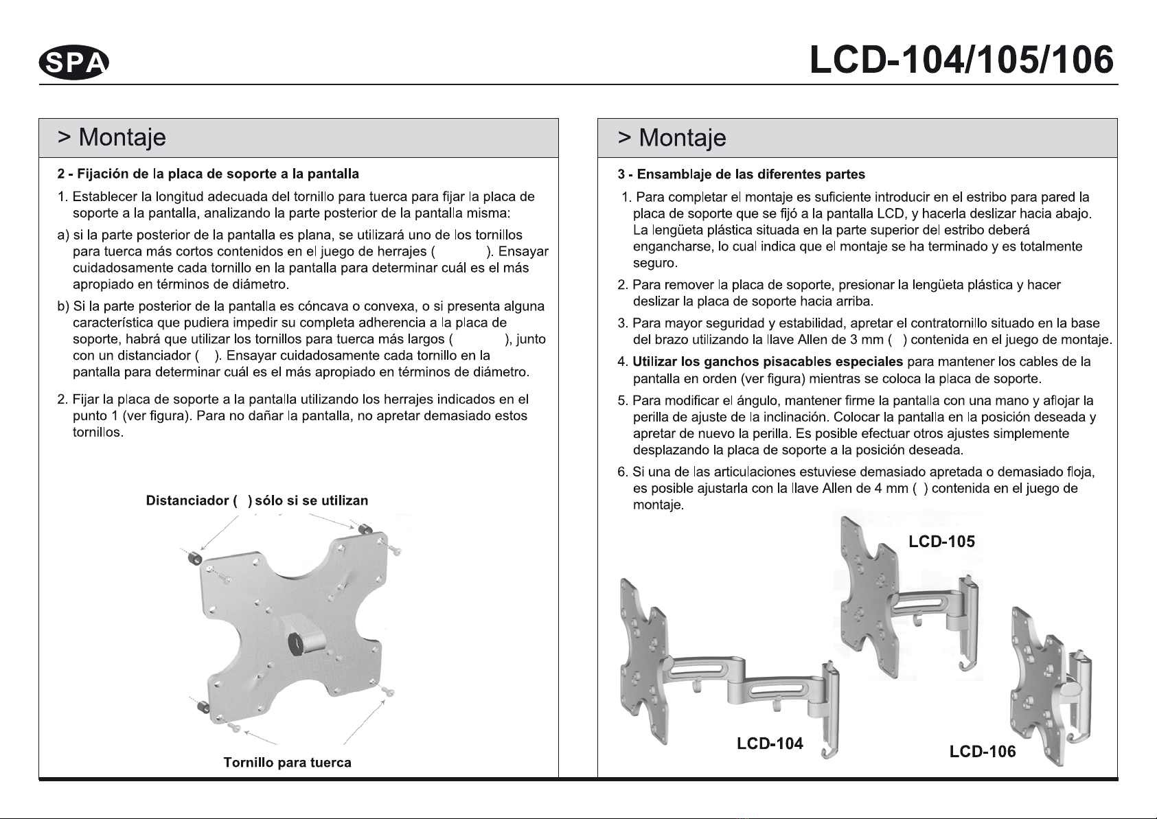
1. Determine the proper length of bolt for attaching the mount to your display by examin-
ing the back of the display:
1.To complete the installation, simply slide the mount with your LCD attached into the
wall piece. The plastic tab at the top of wall piece should click indicating that the mount
is secure.
2. To remove the mount,push in on the plastic tab and then slide the mount up.
3. For additional security and stability,tighten the set screw located on the base of the arm
piece using the 3 mm Allen Key (M) supplied in the hardware kit.
4. Use the cable management hook (see illustration) to keep the power cord and other
cables for your display in order while adjusting the mount.
5. To change the tilt angle,hold the display with one hand and loosen the tilt adjustment
knob.Move the display to the desired position and re-tighten the knob.Other adjust-
ments can be made by simple moving the mount into the desired position.
6. If you find that a joint is too difficult to move or has become too loose,you can adjust
the tightness of that joint using the 4 mm Allen Key (N) supplied in the hardware kit.
2. Attach the mount to your display using the hardware determined in Step 1 (see illustra-
tion). To avoid damage to your display, do not over-tighten these bolts.
a) If your display has aflat back, you will use one of the shorter bolts from the
hardware kit (C, E, G or H). Carefully test each of the shorter bolts with your display
to determine the correct diameter to use.
b) If the back of your display is curved or recessed, or if there are any obstructions
preventing the mount from resting flat against the back, you will use one of the
longer bolts (D, F, H or J) along with a spacer (L). Carefully test each of the longer
bolts with your display to determine the correct diameter to use.
Part2- Attach the Mount To Your Display Part 3 - Slide the Pieces Together
Spacer (
L
)
Only if using
D, F, H or J
Bolt (
C, D, E, F, G, H, I or J
)

LC-32RD8E
(A) Drywall Screw x2 (C) M4 x12 x4 (E) M5 x12 x4
(F) M5 x25 x4
(G) M6 x12 x4 (I) M8 x 12 x4
(J) M8 x25 x4(D) M4 x25 x4 (H) M6 x25 x4(B) x2
(M) 3 mmx1 (N) 4 mmx1
(K) M6 x4 (L) 10mm x4

C, E, G o H
D, F, H o J
L
LD, F, H o J
C, D, E, F, G, H, I o J
M
N

(A) Drywall Screw x2 (C) M4 x12 x4 (E) M5 x12 x4
(F) M5 x25 x4
(G) M6 x12 x4 (I) M8 x 12 x4
(J) M8 x25 x4(D) M4 x25 x4 (H) M6 x25 x4(B) x2
(M) 3 mmx1 (N) 4 mmx1
(K) M6 x4 (L) 10mm x4

(C,D,E,F,G,H,I ou J)
C, E, G ou H
D, F, H ou J
D, F, H ou J
L
L
M
N

(A) Drywall Screw x2 (C) M4 x12 x4 (E) M5 x12 x4
(F) M5 x25 x4
(G) M6 x12 x4 (I) M8 x 12 x4
(J) M8 x25 x4(D) M4 x25 x4 (H) M6 x25 x4(B) x2
(M) 3 mmx1 (N) 4 mmx1
(K) M6 x4 (L) 10mm x4

C, E, G oder H
L
L
M
N
D, F, H oder J
D, F, H oder J
C,D,E,F,G,H,I oder J
(A) Drywall Screw x2 (C) M4 x12 x4 (E) M5 x12 x4
(F) M5 x25 x4
(G) M6 x12 x4 (I) M8 x 12 x4
(J) M8 x25 x4(D) M4 x25 x4 (H) M6 x25 x4(B) x2
(M) 3 mmx1 (N) 4 mmx1
(K) M6 x4 (L) 10mm x4
C, E, G ò H
L
L
M
N
D, F, H ò J
D, F, H ò J
C,D,E,F,G,H,I ò J
(A) Drywall Screw x2 (C) M4 x12 x4 (E) M5 x12 x4
(F) M5 x25 x4
(G) M6 x12 x4 (I) M8 x 12 x4
(J) M8 x25 x4(D) M4 x25 x4 (H) M6 x25 x4(B) x2
(M) 3 mmx1 (N) 4 mmx1
(K) M6 x4 (L) 10mm x4

C, E, G ou H
L
L
M
N
D, F, H ou J
D, F, H ou J
C,D,E,F,G,H,I ou J
This manual suits for next models
2


