GCAN GCAN-IO-8000 User manual

GCAN-IO-8000
CANopen bus coupler
User manual
Document version: V3.25 (2019/03/20)

2
Shenyang Guangcheng Technology Co., Ltd. CANopen bus coupler—GCAN-IO-8000
Product data sheet Shenyang Guangcheng Technology CO.LTD.
revise history
Version
Date
The reason
V1.00
2015/10/16
Create document
V2.01
2015/12/20
Correct equipment working parameters
V3.01
2017/11/22
Add some parameters
V3.02
2018/01/22
Add communication protocol section
V3.03
2018/03/22
Correct equipment working parameters
V3.25
2019/3/20
Modify selection table

3
Shenyang Guangcheng Technology Co., Ltd. CANopen bus coupler—GCAN-IO-8000
Product data sheet Shenyang Guangcheng Technology CO.LTD.
catalog
1. Function introduction.................................................................................................4
1.1 Functional Overview........................................................................................4
1.2 Performance characteristics .............................................................................4
1.3 Typical applications .........................................................................................5
2. Equipment installation and use..................................................................................5
2.1 Module appearance and dimensions................................................................5
Figure 2.1 Appearance of GCAN-IO-8000 CANopen bus coupler.......................5
2.1 Module fixing...................................................................................................5
2.2 Wiring method .................................................................................................7
2.3 System status indicator..................................................................................9
3. Communication connection.....................................................................................11
3.1 Serial port connection....................................................................................11
3.2 CAN connection.............................................................................................11
Table 3.1 Baud rate and maximum bus length reference table............................12
3.3 CAN bus termination resistance ....................................................................12
3.4 Setting of CAN baud rate and node number..................................................12
4. Communication protocol .........................................................................................15
4.1 NMT command..............................................................................................15
Figure 4.3 NMT command monitoring interface.................................................17
4.2 Equipped with GC-1008 module...................................................................17
4.3 Equipped with GC-2008 module...................................................................18
4.4 Equipped with GC-3804 module...................................................................19
4.5 Equipped with multiple sets of modules at the same time.......................20
5. Technical specifications ...........................................................................................23
6. GC series module selection table.............................................................................24
Appendix A: CAN2.0A protocol frame format............................................................26
Appendix B: Introduction to CANopen Protocol ........................................................27
B.1 Explanation of related terms and writing rules .............................................27
B.2 Predefined CAN identifier ............................................................................28
.......................................................................29
B.4 CANopen communication.............................................................................29
B.5 CANopen network configuration..................................................................34
Sales and Service .........................................................................................................35

4
Shenyang Guangcheng Technology Co., Ltd. CANopen bus coupler—GCAN-IO-8000
Product data sheet Shenyang Guangcheng Technology CO.LTD.
1. Function introduction
1.1 Functional Overview
GCAN-IO-8000 CANopen bus coupler can be used to connect CAN bus system and
distributed bus terminal modules. These terminal modules can be expanded in a
modular manner. A complete node consists of a bus coupler, 1-32 any number of
terminal modules and a terminal terminal module. Adopt GCAN-IO-8000 bus coupler,
through GC-bus expansion technology, can establish I/O connection very
conveniently, can connect up to 32 input/output terminal modules.
GCAN-IO-8000 CANopen bus coupler adopts CAN bus protocol that conforms to
ISO 11898 standard. The GCAN-IO-8000 bus coupler not only supports all types of
CANopen communication, but can also be easily applied to manufacturer-specific
CAN bus environments. In addition, the firmware can be upgraded through the
configuration interface.
GCAN-IO-8000 bus coupler can connect all bus terminal modules. As far as the user
is concerned, the processing of analog input/output signals is no different from the
processing of other types of signals. The information in the process image area of the
controller is displayed in byte array format.According to different models, the analog
bus terminal module register contains the temperature range, gain value and linearized
characteristic curve.
GCAN-IO-8000 bus coupler supports automatic configuration, you do not need to set
parameters on the PC. The CANopen baud rate of the GCAN-IO-8000 bus coupler
can be configured via the RS-232 interface.
1.2 Performance characteristics
CANopen baud rate supports 1000k, 500k, 250k, 125k, 100k, 50k, 10k;
PDO mode supports synchronization, loop, event-driven, and polling;
The number of bus terminal modules is 32;
Send 12 PDO (CANopen), receive 12 PDO (CANopen);
The configuration mode is automatic configuration;
The CAN bus interface is an open 4-pin terminal;
The power supply adopts 24V DC (-15%/+20%);
The input current is 70mA+ (total GC-bus current), the maximum is 2.5A;
Starting current: about 2.5 times the continuous current;
Power supply: Max 24V DC/Max 10A;
The electrical isolation is 1500 Vrms;
Working temperature range: -40℃~+85℃;
Dimensions: length 100mm * width 69mm * height 48mm.

5
Shenyang Guangcheng Technology Co., Ltd. CANopen bus coupler—GCAN-IO-8000
Product data sheet Shenyang Guangcheng Technology CO.LTD.
1.3 Typical applications
Connect with the distributed bus terminal module to form a complete control node;
Perform data collection and data transmission with CANopen protocol.
2. Equipment installation and use
This chapter will explain in detail the installation method, wiring method, the
meaning of the indicator light and the meaning of the interface of GCAN-IO-8000
CANopen bus coupler.
2.1 Module appearance and dimensions
The appearance of GCAN-IO-8000 is shown in Figure 2.1. GCAN-IO-8000
CANopen bus coupler includes 2 communication interfaces, 1 controller
programming interface, 1 group controller power interface, 2 groups I/O power
interface, 2 groups shielded wire interface. Among them, the communication interface
includes a CAN bus interface and an RS232 interface.
Figure 2.1 Appearance of GCAN-IO-8000 CANopen bus coupler
2.1 Module fixing
The installation method of GCAN-IO-8000 CANopen bus coupler is shown in figure
2.2, you need to use a flat screwdriver for auxiliary installation.

6
Shenyang Guangcheng Technology Co., Ltd. CANopen bus coupler—GCAN-IO-8000
Product data sheet Shenyang Guangcheng Technology CO.LTD.
Figure 2.2 GCAN-IO-8000 module installation
Figure 2.3 GCAN-IO-8000 module self-locking mechanism
Please install the GCAN-IO-8000 CANopen bus coupler on the guide rail as shown in
Figure 2.3 until the latch snaps and makes a “click” sound. GCAN-IO-8000 CANopen
bus coupler has a self-locking mechanism, which can effectively prevent the device
from falling. As shown in Figure 2.3, you can release the self-locking mechanism by
pulling out the orange label.
GCAN-IO-8000 CANopen bus coupler can connect up to 32 distributed bus terminal
modules. When inserting the bus terminal module, be sure to follow the groove and
insert it on the right side of the existing module in sequence until the latch snaps and
makes a “click” sound. At the far right end of the entire node, you need to install a
terminal module. The terminal can guarantee the data transmission and power supply
of GC-Bus.
When you assemble the nodes correctly, there will be no obvious gaps between the

7
Shenyang Guangcheng Technology Co., Ltd. CANopen bus coupler—GCAN-IO-8000
Product data sheet Shenyang Guangcheng Technology CO.LTD.
terminal modules. If the modules are not assembled correctly, the entire node will not
operate normally.
2.2 Wiring method
As shown in Figure 2.4, use a flat-blade screwdriver to insert into the square hole,
press the upper edge of the metal sheet in the square hole, and press firmly in the
direction of the round hole. Then insert the cable into the circular hole. After plugging
in, pull out the screwdriver, and the cable can be firmly locked in the circular hole
.
Figure 2.4 Wiring of GCAN-IO-8000 module power supply

8
Shenyang Guangcheng Technology Co., Ltd. CANopen bus coupler—GCAN-IO-8000
Product data sheet Shenyang Guangcheng Technology CO.LTD.
Figure 2.5 GCAN-IO-8000 module power terminal block
The power terminal block of GCAN-IO-8000 CANopen bus coupler is shown in
Figure 2.5. The GCAN-IO-8000 CANopen bus coupler contains 8 terminals, and the
corresponding serial numbers and meanings of each terminal are shown in Table 2.1.
Please note that between terminal 3 and terminal 4, between terminal 5 and terminal 6,
and between terminal 7 and terminal 8 are connected inside the module.
Terminal
Serial number
meaning
24V
1
Power 24V input
0V
2
Power GND
+
3
IO power supply is positive
+
4
IO power supply is positive
-
5
IO power negative
-
6
IO power negative
PE
7
shield
PE
8
shield
Table 2.1 Definition of GCAN-IO-8000 module power terminal

9
Shenyang Guangcheng Technology Co., Ltd. CANopen bus coupler—GCAN-IO-8000
Product data sheet Shenyang Guangcheng Technology CO.LTD.
Figure 2.6 GCAN-IO-8000 module CAN bus terminal block
The CAN bus terminal block of GCAN-IO-8000 CANopen bus coupler is shown in
Figure 2.6. The CAN bus terminal block of GCAN-IO-8000 contains 4 terminals, and
the corresponding serial number and meaning of each terminal are shown in Table 2.2.
Terminal
Serial number
meaning
CAN-H
1
CANopen high
PE
2
Shielded wire
CAN-L
3
CANopen low
CAN-G
4
CANopen ground
Table 2.2 Definition of CAN bus terminal of GCAN-IO-8000 module
Figure 2.7 GCAN-IO-8000 module RS-232 interface definition
The definition of RS-232 interface of GCAN-IO-8000 CANopen bus coupler is
shown in Figure 2.7. GCAN-IO-8000's RS-232 interface only defines three signal
lines, namely RXD, TXD and GND.
2.3 System status indicator
GCAN-IO-8000 CANopen bus coupler has two sets of status indicators. The left area
contains 6 circular status indicators, and the right area contains 2 small power
indicators. The specific indication function of the indicator light is shown in Table 2.3.
When the indicator lights are in different states, the state of the GCAN-IO-8000
module is shown in Table 2.4.
Indicator light
colour
Indication status
PWR
green
Power indicator
SYS
green
System instructions

10
Shenyang Guangcheng Technology Co., Ltd. CANopen bus coupler—GCAN-IO-8000
Product data sheet Shenyang Guangcheng Technology CO.LTD.
RUN
green
Operating instructions
ERR
green
Error indication
IO RUN
green
Internal bus operation instructions
IO ERR
green
Internal bus error indication
Position 1 on the right
green
Power indicator
Position 3 on the right
green
Internal bus power indication
Table 2.3 GCAN-IO-8000 module indicator
Indicator light
status
Indication status
PWR
Always on
Power supply is normal
not bright
Abnormal power supply
SYS
flicker
The device is initialized and enters
the working state
not bright
Device initialization failed
RUN
flicker
The device is operating normally
not bright
Device operation stopped
ERR
Always on
system error
not bright
No errors in the system
IO RUN
flicker
The internal bus is operating
normally
not bright
Internal bus stop
IO ERR
Always on
Internal bus operation error
not bright
No error occurred during internal
bus operation
Position 1 on the right
Always on
Normal power supply on the
terminal side
not bright
Abnormal power supply on the
terminal side
Position 3 on the right
Always on
The internal bus power supply of
the terminal is normal
not bright
Abnormal internal bus power
supply of the terminal
Table 2.4 GCAN-IO-8000 module indicator status
11
Shenyang Guangcheng Technology Co., Ltd. CANopen bus coupler—GCAN-IO-8000
Product data sheet Shenyang Guangcheng Technology CO.LTD.
3. Communication connection
3.1 Serial port connection
GCAN-IO-8000 CANopen bus coupler uses standard serial port level (RS232:
±3~15V), so the module can be directly connected to devices with RS232 interface.
The baud rate of the RS232 interface of the GCAN-IO-8000 CANopen bus coupler
cannot be modified and is fixed at 19200bps.
3.2 CAN connection
GCAN-IO-8000 module is connected to the CAN bus as described in 2.2. Connect
CAN_H to CAN_H and CAN_L to CAN_L to establish communication.
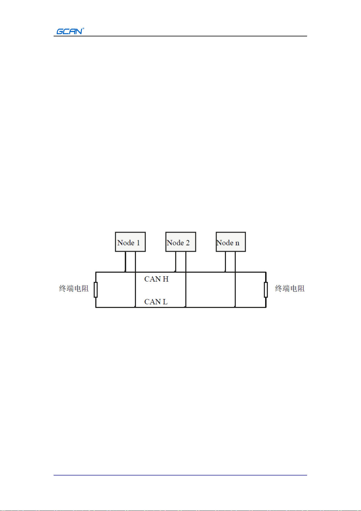
The CAN-bus network adopts a straight-line topology structure, and the two furthest
terminals of the bus need to install 120Ω terminal resistance; if the number of nodes is
greater than 2, the intermediate nodes do not need to install 120Ω terminal resistance.
For branch connections, the length should not exceed 3 meters. The connection of
CAN-bus bus is shown in Figure 3.1.
Figure 3.1 Topology of CAN-bus network
Please note: CAN-bus cable can use ordinary twisted pair and shielded twisted
pair. The theoretical maximum communication distance mainly depends on the
bus baud rate. For the relationship between the maximum bus length and baud
rate, see Table 3.1. If the communication distance exceeds 1km, the
cross-sectional area of the line should be greater than Φ1.0mm2, the specific
specifications should be determined according to the distance, and the
conventional is to increase appropriately as the distance increases.
12
Shenyang Guangcheng Technology Co., Ltd. CANopen bus coupler—GCAN-IO-8000
Product data sheet Shenyang Guangcheng Technology CO.LTD.
Baud rate
Bus length
1 Mbit/s
40m
500 kbit/s
110m
250 kbit/s
240m
125 kbit/s
500m
50 kbit/s
1.3km
20 kbit/s
3.3km
10 kbit/s
6.6km
5 kbit/s
13km
Table 3.1 Baud rate and maximum bus length reference table
3.3 CAN bus termination resistance
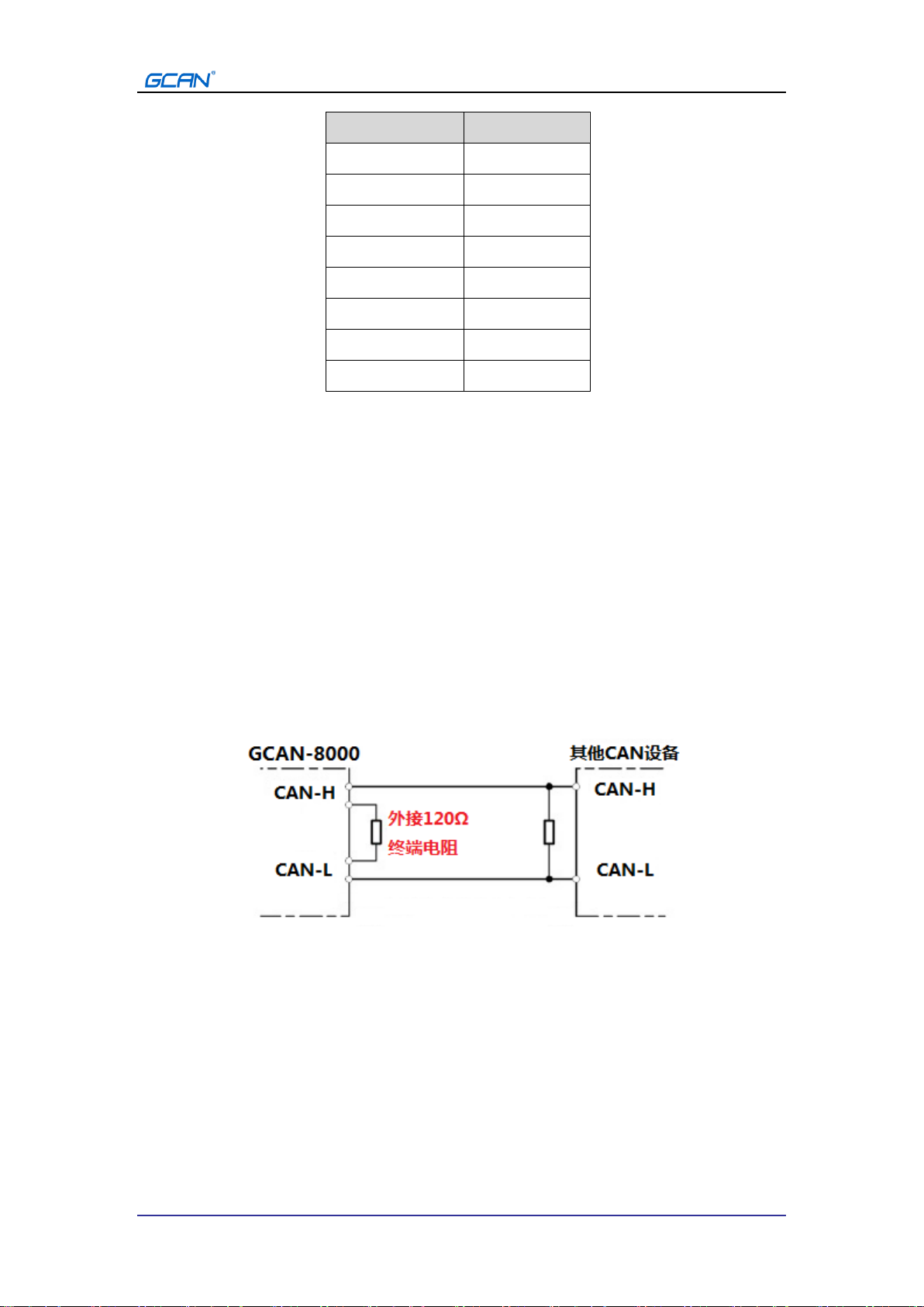
In order to enhance the reliability of CAN communication and eliminate CAN bus
terminal signal reflection interference, the two farthest endpoints of the CAN bus
network usually need to add terminal matching resistors, as shown in Figure 3.2. The
value of the termination matching resistance is determined by the characteristic
impedance of the transmission cable. For example, the characteristic impedance of the
twisted pair is 120Ω, then the two endpoints on the bus should also integrate 120Ω
termination resistors. If other nodes on the network use different transceivers, the
termination resistance must be calculated separately.
Figure 3.2 GCAN-IO-8000 connected with other CAN node devices
Please note: The 120Ω termination resistor is not integrated inside the
GCAN-IO-8000 module. If the number of nodes is greater than 2, the
intermediate node does not need to install a 120Ω termination resistor. When
needed, connect CAN_H and CAN_L at both ends of the resistor, as shown in
Figure 3.2.
3.4 Setting of CAN baud rate and node number
You can modify the CAN bus communication baud rate of the GCAN-IO-8000
module through the RS232 interface. The specific process is as follows: first establish

13
Shenyang Guangcheng Technology Co., Ltd. CANopen bus coupler—GCAN-IO-8000
Product data sheet Shenyang Guangcheng Technology CO.LTD.
a serial port connection, the baud rate is 19200bps, the data bit and stop bit are
configured as none, 8, 1, send a "help" command or "?" command through the RS232
interface, and then the RS232 interface will return to the configuration information.
Please note that when sending the command, please add a carriage return at the
end or select the "send new line" of the software. For display and transmission,
please do not select "hexadecimal display" or "hexadecimal transmission". You can
send "setbaud=500000" to modify the baud rate of the GCAN-IO-8000 module to
500kbps. At the same time, you can send "getbaud" to get the CAN baud rate of the
machine, and the unit of the reply value is bps. The detailed baud rate correspondence
is shown in Table 3.2. The settings when sending the request command are shown in
Figure 3.3.
Figure 3.3 Settings when sending a request command
baud setting value
Corresponding baud rate
(kbps)
setbaud=1000000
1000
setbaud=500000
500
setbaud=250000
250
setbaud=125000
125
setbaud=100000
100
setbaud=50000
50
setbaud=10000
10
Table 3.2 Baud setting value and baud rate comparison table
The method of setting and obtaining the CANopen node ID is similar to the baud rate.

14
Shenyang Guangcheng Technology Co., Ltd. CANopen bus coupler—GCAN-IO-8000
Product data sheet Shenyang Guangcheng Technology CO.LTD.
You can modify the CAN bus node number of the GCAN-IO-8000 module through
the RS232 interface. You can send "setid=3" to modify the CANopen node ID of
GCAN-IO-8000 module to 3. At the same time, you can send "getid" to get the
CANopen node ID of this machine. The node number can be set arbitrarily within
1-127.

15
Shenyang Guangcheng Technology Co., Ltd. CANopen bus coupler—GCAN-IO-8000
Product data sheet Shenyang Guangcheng Technology CO.LTD.
4. Communication protocol
GCAN-IO-8000 implements CANopen communication protocol and is a CANopen
slave device. The GCAN-IO-8000 module uses PDO (Process Data Object) to collect
or output digital signals.
When equipped with GC-3804 or GC-1008 module, GCAN-IO-8000 will send out
TPDO data, typical frame ID such as 0x181, 0x281, etc. When equipped with
GC-2008 module, GCAN-IO-8000 will receive RPDO data, typical frame ID such as
0x203, 0x303, etc.
In this chapter, Guangcheng Technology USBCAN-II Pro module and ECANTools
software can be used to receive and send CAN bus data. The CANopen master station
function provided with the software can help debug the CANopen slave station, which
is very convenient and practical.
Using the USBCAN bus analyzer of Guangcheng Technology can simulate the CAN
bus communication device and conduct the communication test of the
GCAN-IO-8000 module. The USBCAN bus analyzer is an intuitive CAN bus
debugging and analysis tool. Using this device can monitor and simulate CAN data
transmission and reception through a computer. It is an essential tool for engineers
engaged in the CAN bus industry. You are welcome to purchase through the contact
information on the last page of this manual.
4.1 NMT command
The GCAN-IO-8000 module meets the standard CANopen Cia301 protocol and is a
standard CANopen slave device. After GCAN-IO-8000 is started, it will actively
send a frame command to the master station, the frame ID is 0x700+Node ID,
and the frame data is 0x7F.
For example: Set the Node ID of GCAN-IO-8000 to 1 through the DIP switch, then
USBCAN-II Pro as the master device can receive a start command, the frame ID is
0x701, and the frame data is 0x7F. As shown in Figure 4.1, using ECANTools
software can receive this data.
Frame
ID
(HEX)
DLC
Frame data (HEX)
701
1
7F
--
--
--
--
--
--
--

16
Shenyang Guangcheng Technology Co., Ltd. CANopen bus coupler—GCAN-IO-8000
Product data sheet Shenyang Guangcheng Technology CO.LTD.
Figure 4.1 Start command monitoring interface
The GCAN-IO-8000 module receives the operation command issued by the
master station, the frame ID is 0x000, the DLC is 2, the first byte of the frame
data is the command symbol, and the second byte is the node number (00 is all
nodes) .
For example: The node ID of GCAN-IO-8000 is 1, and the command GCAN-IO-8000
is to enter the operation state (01), then the NMT command frame ID is 0x000, and
the frame data is 0x01,0x01. This command can also be issued by the
CANopenMaster plug-in of the ECANTools software. For detailed instructions of
NMT, please refer to Appendix B.4 CANopen Communication.
Frame
ID
(HEX)
DLC
Frame data (HEX)
000
2
Comman
d
Node address
01
01
--
--
--
--
--
--
17
Shenyang Guangcheng Technology Co., Ltd. CANopen bus coupler—GCAN-IO-8000
Product data sheet Shenyang Guangcheng Technology CO.LTD.
Figure 4.2 NMT command sending interface
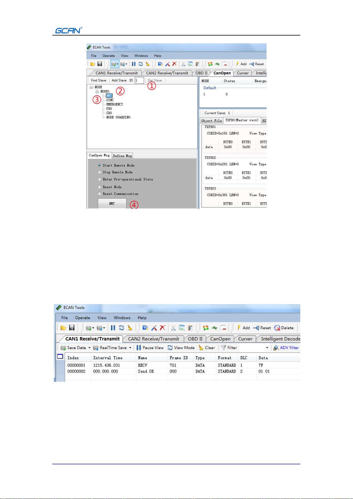
Use the ECANTools software to command GCAN-IO-8000 to enter the operation
state: ①fill the slave node number into the text box behind the ID, ②click the add
slave button, ③open the + sign on the left of the node, and click " NMT", ④
Select "Start Remote Node" (default) and click the "NMT" button below. As shown in
Figure 4.3, the NMT command can be viewed in the ECANTools monitoring interface
after sending.
After receiving the NMT command, GCAN-IO-8000 will start broadcasting PDO data
and issue a heartbeat command with frame ID 0x701 and frame data 0x05, indicating
that GCAN-IO-8000 has entered the operating state.
Figure 4.3 NMT command monitoring interface
4.2 Equipped with GC-1008 module
The state of the digital input is represented by a byte, channel 8 is in the high bit, and
channel 1 is in the low bit.
For example, the node number of the GCAN-IO-8000 module is set to 1. The state of

18
Shenyang Guangcheng Technology Co., Ltd. CANopen bus coupler—GCAN-IO-8000
Product data sheet Shenyang Guangcheng Technology CO.LTD.
channel 8 and channel 4 is 1, and the other states are all 0, then the DI status data
displayed on one end of the CAN bus is 88. The frame ID sent is 0x181, the data
length (DLC) is 8, the frame data is 0x88, 0x00, 0x00, 0x00, 0x00, 0x00, 0x00, 0x00.
Please note that when only one GCAN-1008 module is inserted, only the first byte in
the frame data is valid. The following table lists two common DI states and their
corresponding state data.
DI status
Number
of
channels
8
7
6
5
4
3
2
1
status
1
0
0
0
1
0
0
0
Data
displayed
on the
CAN bus
88
DI status
Number
of
channels
8
7
6
5
4
3
2
1
status
0
1
0
1
1
0
1
0
Data
displayed
on the
CAN bus
5A
When only one GCAN-1008 module is inserted, the TPDO data frame ID issued by
the GCAN-IO-8000 module is 0x180+node ID (Node ID), the data length is 8, and the
first byte of the frame data is the digital input status of the module .
4.3 Equipped with GC-2008 module
The state of the digital output is represented by a byte, channel 8 is in the high bit, and
channel 1 is in the low bit.
For example, the node number of the GCAN-IO-8000 module is set to 1. Need to set
the state of channel 8 and channel 4 to 1, and set all other states to 0, then the CAN

19
Shenyang Guangcheng Technology Co., Ltd. CANopen bus coupler—GCAN-IO-8000
Product data sheet Shenyang Guangcheng Technology CO.LTD.
bus DO status data to be sent is 88. The frame ID to be sent to GCAN-IO-8000 is
0x201, the data length (DLC) is 8, and the frame data is 0x88, 0x00, 0x00, 0x00, 0x00,
0x00, 0x00, 0x00. Please note that only the first byte in the frame data is valid. The
following table lists two common DO states and their corresponding state data.
DO status
Number
of
channels
8
7
6
5
4
3
2
1
status
1
0
0
0
1
0
0
0
Data
displayed
on the
CAN bus
88
DO 状态
Number
of
channels
8
7
6
5
4
3
2
1
status
0
1
0
1
1
0
1
0
Data
displayed
on the
CAN bus
5A
When receiving the RPDO data, the GCAN-IO-8000 module needs to ensure that the
frame ID is 0x200 + node ID (Node ID), the data length is 8, and the first byte of the
frame data is the digital output status that needs to be set.
4.4 Equipped with GC-3804 module
The temperature status of each channel is represented by two bytes, and the four
channels have a total of eight bytes.
Among them, the two bytes representing the temperature status, the first byte is the
low bit, the data of the byte needs to be converted to decimal and multiplied by 0.1;
the second byte is the high bit, the data of the byte needs to be converted Multiply by
25.6 after decimal. Finally, the two values are added together to obtain the final
temperature value in degrees Celsius.
For example, the node number of the GCAN-IO-8000 module is set to 1. The
temperatures of the four channels are 25.6 degrees, 25.5 degrees, 20 degrees, and 30
degrees, respectively. The frame ID sent is 0x181, the data length (DLC) is 8, the
frame data is 0x00, 0x01, 0xFF, 0x00, 0xC8, 0x00, 0x2C, 0x01. The following table
lists two possible CAN data and their corresponding temperature values.
20
Shenyang Guangcheng Technology Co., Ltd. CANopen bus coupler—GCAN-IO-8000
Product data sheet Shenyang Guangcheng Technology CO.LTD.
Correspondence between GC-3804 temperature and CAN data
Data
displayed on
the CAN
bus
Low byte C8
High byte 00
coefficient
200(0xC8)x0.1
0(0x00)x25.6
Temperatur
e value
20℃
Correspondence between GC-3804 temperature and CAN data
Data
displayed on
the CAN
bus
Low byte 2C
High byte 01
coefficient
44(0x2C)x0.1
1(0x01)x25.6
Temperatur
e value
30℃
When the GCAN-IO-8000 module sends out TPDO data, the frame ID is 0x180+node
ID (Node ID), and the data length is 8. If PT100 is not connected, the CAN data of the
corresponding channel will be displayed as FF 7F.
4.5 Equipped with multiple sets of modules at the same
time
If GCAN-IO-8000 is equipped with multiple sets of GC-1008 modules at the same
time, then we will number them according to their distance from GCAN-IO-8000
from near to far, and the nearest one is No. 1. The TPDO data sent by the
GCAN-IO-8000 coupler will be sent according to the following table. For example,
when the GCAN-IO-8000 node number is 3 and it is equipped with 9 GC-1008
modules at the same time, you will receive two sets of data with frame IDs 0x183 and
0x283. Among them, the eight data bytes with the frame ID of 0x183 correspond to
the GC-1008 module No. 1-8 in turn; the one data byte with the frame ID of 0x283
corresponds to the GC-1008 module No. 9.
Table 4.1 Correspondence between multiple sets of GC-1008 modules and CAN data
Frame ID
Frame data
0x180+Node ID
1
2
3
4
5
6
7
8
0x280+Node ID
9
10
11
12
13
14
15
16
0x380+Node ID
17
18
19
20
21
22
23
24
0x480+Node ID
25
26
27
28
29
30
31
32
Other manuals for GCAN-IO-8000
1
Table of contents
Popular Industrial Equipment manuals by other brands

Ditch Witch
Ditch Witch FX20 Operator's manual

Alfalaval
Alfalaval Toftejorg MultiMidget instruction manual

Burger & Brown
Burger & Brown SMARTFLOW FasTie installation instructions

Delta
Delta HEX150PB Series instruction manual

Alfalaval
Alfalaval COMPABLOC CP15 Installation, operation and maintenance manual

woodmizer
woodmizer LubeMizer manual


