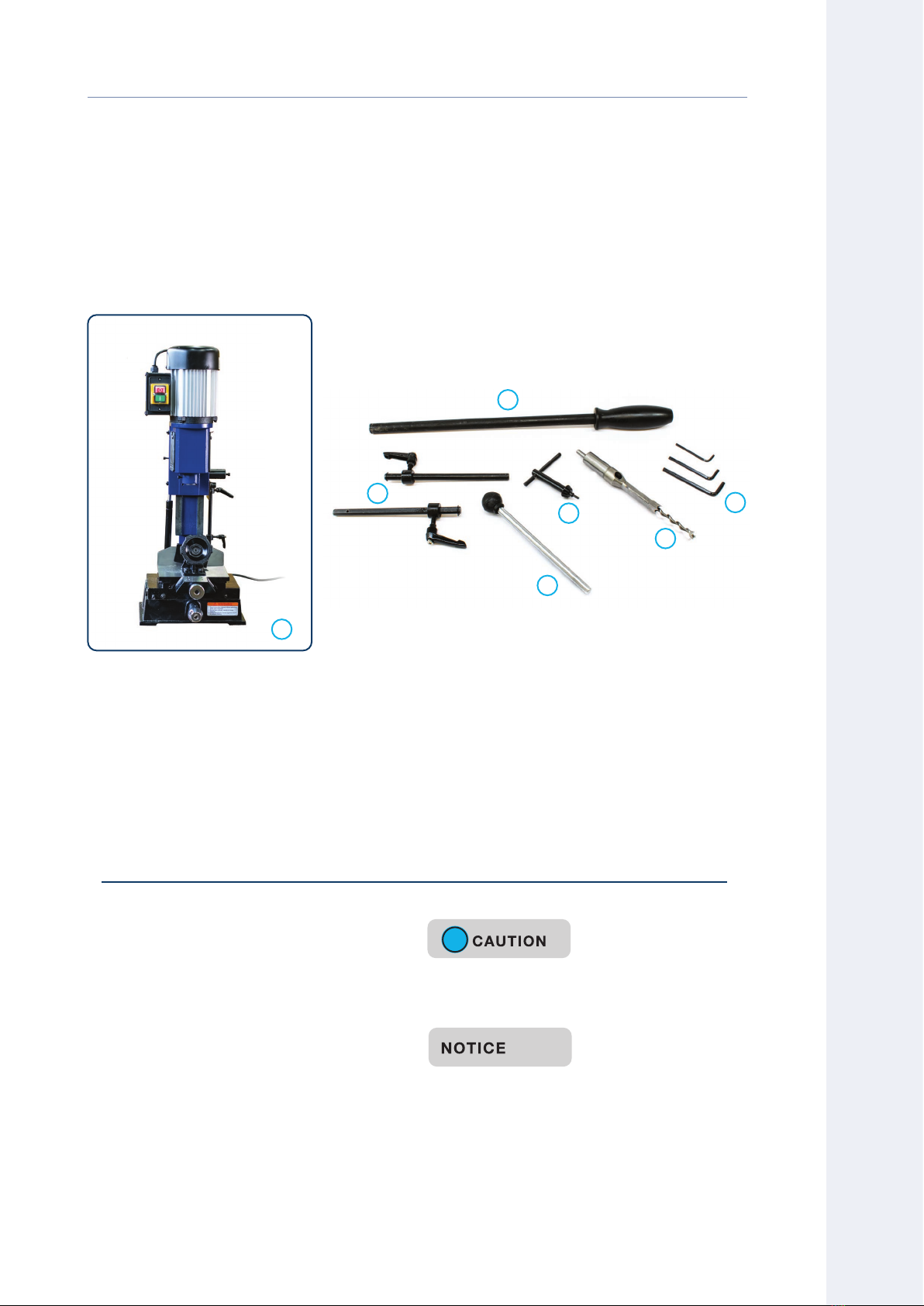
Carbatec MM-B375P User manual

CARBATEC.COM.AU
MMB375P MANUAL
Benchtop Chisel Mortiser
2

FOR TECHNICAL SUPPORT CALL 1800 658 111
2
MM-B375P
V1
Carbatec has been a trusted brand for woodworking enthusiasts
and professionals across Australia and New Zealand, since 1987.
Our quality woodworking products are designed and built to oer
value and performance, making the latest features and technological
advancements more accessible to Aussie woodworkers.
Backed by our no-fuss after-sales care and warranty support,
you can trust Carbatec to keep you woodworking, as promised.
We look forward to sharing in your woodworking journey!
If you have any questions about our products or service,
please call us on 1800 658 111 or email us at info@carbatec.com.au
Find us on social media
facebook.com/Carbatec
instagram.com/Carbatec
youtube.com/CarbaTecToolsForWood
THANK YOU
FOR CHOOSING

CARBATEC.COM.AU
3
MM-B375P
If you cannot nd an item on this list, carefully
check around and inside the machine and
packaging materials. Often, these items get lost in
packaging materials while unpacking or they are
pre-installed at the factory.
!
DO NOT use acetone, gasoline or lacquer thinner
to remove any protective coatings.
1. Remove parts from all of the cartons
and lay them on a clean work surface.
2. Remove any protective materials and
coatings from all of the parts of the cyclone
dust extractor. The protective coatings can
be removed by spraying WD-40 on them and
wiping it o with a soft cloth. This may need
to be redone several times before all of the
protective coatings are removed completely.
3. Compare the items above to verify that all
items are accounted for before discarding
the shipping box.
G
F
E
D
C
B
A
A. Pre-assembled chisel mortiser
B. Hand lever
C. Lateral travel stop and handles
D. Handle for lateral adjustment of table
E. Chuck key
F. Chisel
G. Allen keys
The following items are provided in 1 carton.
WHAT’S IN THE BOX
WELCOME
MMB375P BENCHTOP CHISEL MORTISER

FOR TECHNICAL SUPPORT CALL 1800 658 111
4
MM-B375P
DATE OF PURCHASE:
SERIAL NUMBER:
Record the serial number and date of purchase
in your manual for future reference.
2
Made for
CARBATEC PTY LTD
Brisbane - Australia
Model:
Voltage
Freq:
Phase:
Amp:
kW:
Speed:
Lot No.:
Serial No.:
Date:
QUALITY INSPECTED
Key information can be found on the inspection
panel, found on the rear of the machine.
IMPORTANT

CARBATEC.COM.AU
5
MM-B375P
NOTE: The specifications, photographs, drawings and information in this manual represent
the current machine model when the manual was prepared. Changes and improvements
may be made at any time, with no obligation on the part of Carbatec to modify previously
delivered units. Reasonable care has been taken to ensure that the information in this
manual is correct, to provide you with the guidelines for the proper safety, assembly and
operation of this machine.
Introduction 2
What’s in the box 3
Key information 4
Safety instructions - General 6–9
Safety instructions - Chisel Mortiser 9–10
Safety instructions - Electrical 11
Overview 12
Specications 13
Assembly 14–19
Operation 20–21
Maintenance 22
Troubleshooting 23–24
Wiring diagram 24
Parts diagrams/Parts list 25–26
Warranty 27
CONTENTS
CONTENTS

FOR TECHNICAL SUPPORT CALL 1800 658 111
6
MM-B375P
A safety alert symbol Indicates DANGER, WARNING, or CAUTION.
May be used in conjunction with other symbols or pictographs.
Indicates an imminently hazardous situation, which, if not avoided,
will result in death or serious injury.
Indicates a potentially hazardous situation, which, if not avoided,
could result in death or serious injury.
Indicates a potentially hazardous situation, which, if not avoided,
could result in minor or moderate injury.
(Without Safety Alert Symbol) Indicates a situation that may result
in property damage.
Carbatec products bearing the Regulatory Compliance Mark (RCM) have been
tested in accordance with applicable Australian/New Zealand Standards
to ensure their compliance with all mandatory standards and regulations
(applicable at time of original sale). Carbatec Pty Ltd are registered as a
responsible supplier with relevant Australian government departments and
our products are registered on the EESS & ACMA database.
!
!
!
!
SYMBOL MEANING
IMPORTANT! Safety is the single most important consideration in the operation of this
equipment. The following instructions must be followed at all times. Failure to follow all
instructions listed below may result in electric shock, re, and/or serious personal injury.
There are certain applications for which this tool was designed. We strongly recommend
that this tool not be modied and/or used for any other application other than that for
which it was designed. If you have any questions about its application, do not use the tool
until you have contacted us and we have advised you.
The purpose of safety symbols is to attract your attention to possible dangers. The safety
symbols and the explanations with them deserve your careful attention and understanding.
The symbol warnings do not, by themselves, eliminate any danger. The instructions and
warnings they give are no substitutes for proper accident prevention measures.
!
Be sure to read and understand all safety instructions in this manual, including all safety
alert symbols such as “DANGER,” “WARNING,” and “CAUTION” before using this tool.
Failure to following all instructions listed below may result in electric shock, re, and/or
serious personal injury.
SAFETY INSTRUCTIONS

CARBATEC.COM.AU
7
MM-B375P
Operating a power tool can be dangerous if
safety and common sense are ignored. The
operator must be familiar with the operation of
this machine. Read this manual to understand this
machine. DO NOT OPERATE this machine IF YOU
DO NOT FULLY UNDERSTAND the limitations of
this tool. DO NOT MODIFY this machine in any way.
BEFORE USING
THIS MACHINE
!
To avoid serious injury and damage to the tool,
read and follow all of the Safety and Operating
Instructions before operating the machine.
!
1. SOME DUST CREATED BY USING
POWER TOOLS CONTAINS CHEMICALS
known to cause cancer, birth defects, or
other reproductive harm. Some examples of
these chemicals are:
• Lead from lead-based paints.
• Crystalline silica from bricks, cement, and
other masonry products.
• Arsenic and chromium from chemically
treated lumber
Your risk from these exposures varies,
depending on how often you do this type
of work. To reduce your exposure to these
chemicals: work in a well ventilated area
and work with approved safety equipment,
such as those dust masks that are specially
designed to lter out microscopic particles.
2. READ this entire manual. LEARN how to use
the tool for its intended applications.
3. GROUND ALL TOOLS. If the tool is supplied
with a 3-prong plug, it must be plugged into
a 3-contact electrical receptacle. The third
prong is used to ground the tool and provide
protection against accidental electric shock.
4. AVOID A DANGEROUS WORKING
ENVIRONMENT. Do not use electrical tools in
a damp environment or expose them to rain.
5. DO NOT USE electrical tools in the presence
of FLAMMABLE liquids or gases.
6. ALWAYS KEEP THE AREA CLEAN, well lit,
and organized. Do not work in an environment
with oor surfaces that are slippery from
debris, grease, and wax.
7. KEEP VISITORS AND CHILDREN AWAY. Do
not permit people to be in the immediate
work area, especially when the electrical tool
is operating.
8. DO NOT FORCE THE TOOL to perform an
operation for which it was not designed. It
will do a safer and higher quality job by only
performing operations for which the tool was
intended.
9. WEAR PROPER CLOTHING.
Do not wear loose clothing, gloves, neckties,
or jewellery. These items can get caught in
the machine during operations and pull the
operator into the moving parts. The user
must wear a protective cover on their hair, if
hair is long, to prevent it from contacting any
moving parts.
10. CHILDPROOF THE WORKSHOP AREA by
removing switch keys, unplugging tools from
the electrical receptacles, and using padlocks.
GENERAL SAFETY
SAFETY

FOR TECHNICAL SUPPORT CALL 1800 658 111
8
MM-B375P
11. ALWAYS UNPLUG THE TOOL FROM THE
ELECTRICAL RECEPTACLE
when making adjustments, changing parts or
performing any maintenance.
12. KEEP PROTECTIVE GUARDS IN PLACE AND
IN WORKING ORDER.
13. AVOID ACCIDENTAL STARTING. Make sure
that the power switch is in the “OFF” position
before plugging in the power cord to the
electrical receptacle.
14. REMOVE ALL MAINTENANCE TOOLS from
the immediate area prior to turning “ON”
the machine.
15. USE ONLY RECOMMENDED ACCESSORIES.
Use of incorrect or improper accessories
could cause serious injury to the operator
and cause damage to the tool. If in doubt,
check the instruction manual that comes with
that particular accessory.
16. NEVER LEAVE A RUNNING TOOL
UNATTENDED. Turn the power switch to the
“OFF” position. Do not leave the tool until it
has come to a complete stop.
17. DO NOT STAND ON A TOOL. Serious injury
could result if the tool tips over, or you
accidentally contact the tool.
18. DO NOT STORE ANYTHING ABOVE OR
NEAR the tool where anyone might try to
stand on the tool to reach it.
19. MAINTAIN YOUR BALANCE. Do not extend
yourself over the tool. Wear oil resistant
rubber soled shoes. Keep oor clear of
debris, grease, and wax.
20. MAINTAIN TOOLS WITH CARE. Always
keep tools clean and in good working order.
Keep all blades and tool bits sharp, dress
grinding wheels and change other abrasive
accessories when worn.
21. EACH AND EVERY TIME, CHECK FOR
DAMAGED PARTS PRIOR TO USING THE
TOOL. Carefully check all guards to see that
they operate properly, are not damaged, and
perform their intended functions. Check for
alignment, binding or breaking of moving
parts. A guard or other part that is damaged
should be immediately repaired or replaced.
22. DO NOT OPERATE TOOL WHILE TIRED,
OR UNDER THE INFLUENCE OF DRUGS,
MEDICATION OR ALCOHOL.
23. SECURE ALL WORK. Use clamps or jigs to
secure the work piece. This is safer than
attempting to hold the work piece with
your hands.
24. STAY ALERT, WATCH WHAT YOU ARE
DOING, AND USE COMMON SENSE WHEN
OPERATING A POWER TOOL. A moment of
inattention while operating power tools may
result in serious personal injury.
GENERAL SAFETY

CARBATEC.COM.AU
9
MM-B375P
25. ALWAYS WEAR A DUST MASK TO
PREVENT INHALING DANGEROUS DUST
OR AIRBORNE PARTICLES, including wood
dust, crystalline silica dust and asbestos
dust. Direct particles away from face and
body. Always operate tool in well ventilated
area and provide for proper dust removal. Use
dust extraction system wherever possible.
Exposure to dust may cause serious and
permanent respiratory or other injury,
including silicosis (a serious lung disease),
cancer, and death. Avoid breathing dust, and
avoid prolonged contact with dust. Allowing
dust to get into your mouth or eyes, or lay on
your skin may promote absorption of harmful
material. Always use properly tting AS/NZS
approved respiratory protection appropriate
for the dust exposure, and wash exposed
areas with soap and water.
SAFETY
26. USE A PROPER EXTENSION CORD IN GOOD
CONDITION. Use of extension cords should
be avoided where possible. When using an
extension cord, be sure to have a cord heavy
enough to carry the current your product will
draw, and with compatible pin conguration
and connections. NEVER use an extension
cord rated at less than your machine.
Longer run extensions will need heavier
duty extension cords. Only connect your
extension cord or machine to a receptacle
that accepts your plug and never modify your
plug to suit a receptacle.
CHISEL MORTISER SAFETY
You can be seriously injured or killed by getting
clothing, jewellery, or long hair entangled with
the chisel. Your ngers can be severely cut or
amputated by the chisel. You can be blinded
or hurt by ying wood chips, broken cutting
tools, workpieces, or adjustment tools that can
be thrown from the spinning chuck with great
force. To reduce your risk of serious injury when
operating this machine, completely heed and
understand the following:
HAND PROTECTION
Do not place your hands under or near chisel
while spindle is in motion. Chisels are sharp and
may become hot during operation! Allow chisels
to cool before handling. Always use caution when
handling, especially when installing or removing.
Do not wear gloves while machine is operating.
They may become entangled in the chisel.
USING CORRECT MATERIALS
Mortising materials such as metals, plastics,
and glass can result in serious personal injury
and machine damage. Do not use machine
for anything except mortising in wood. Do not
attempt to mortise material that does not have a
at surface unless a suitable support is used.
CHISEL COMPATIBILITY
Mortising chisels can y out of chuck at operator
if not properly secured, causing serious personal
injury. Ensure mortising chisel is installed a
minimum of 1/2” into chuck.
!

FOR TECHNICAL SUPPORT CALL 1800 658 111
10
MM-B375P
ADJUST DEPTH STOP
Adjust the depth stop to avoid drilling into the
table or work bench.
REMOVE CHUCK KEY
Ensure chuck key is removed before starting
machine. Do not modify chuck key in any way.
ALWAYS TURN POWER OFF:
• when the drill bit or chisel is contacting
the workpiece
• when performing layout, assembly,
or setting up work on the table
• before removing scrap pieces from
the table
• before cleaning the table or work area and
leaving the machine
CHISEL MORTISER SAFETY
INSPECT CUTTING TOOLS
Inspect chisels and augers for sharpness, chips,
or cracks before each use. Replace dull, chipped,
or cracked cutting tools immediately.
INSPECT MACHINE
Loose chisels and augers can be ejected at
operator, and headstock can fall if not properly
secured, causing serious personal injury. Inspect
machine for smooth head casting movement,
loose augers/chisels, loose nuts/bolts, and lock
levers before connecting machine to power and
operating. Correct any problems before use.
SECURE WORKPIECE TO
TABLE
Never hold workpiece by hand during operation.
No list of safety guidelines can be complete. Every shop
environment is different. Always consider safety first, as it applies
to your individual working conditions. Use this and other machinery
with caution and respect. Failure to do so could result in serious
personal injury, damage to equipment, or poor work results.
!

CARBATEC.COM.AU
11
MM-B375P
FIG. BFIG. A
!
This tool must be grounded while in use to
protect the operator from electric shock. IN THE
EVENT OF A MALFUNCTION OR BREAKDOWN,
grounding provides the path of least resistance
for electric current and reduces the risk of electric
shock. This tool may be equipped with an electric
cord that has an equipment grounding conductor
and a grounding plug. The plug MUST Be plugged
into a matching electrical receptacle that is
properly installed and grounded in accordance
with ALL local codes and ordinances.
DO NOT MODIFY THE PLUG PROVIDED.
If it will not t the electrical receptacle, have the
proper electrical receptacle installed by a
qualied electrician.
IMPROPER ELECTRICAL CONNECTION of the
equipment grounding conductor can result in
risk of electric shock. The conductor with the
green insulation (with or without yellow stripes)
is the equipment grounding conductor. DO NOT
connect the equipment grounding conductor to a
live terminal if repair or replacement of the electric
cord or plug is necessary.
CHECK WITH A QUALIFIED ELECTRICIAN
or service personnel if you do not completely
understand the grounding instructions, or if you
are not sure the tool is properly grounded.
Use only a 3-wire extension cord that has a
3-prong grounding plug and a 3-pole receptacle
that accepts the tool’s plug. Replace a damaged
or worn cord immediately.
Power tools and machinery are intended for use
on a circuit that has an electrical receptacle as
shown in FIGURE A that shows a 10 Amp 3-wire
electrical plug and corresponding electrical
receptacle that has a grounding conductor.
If this particular tool has been designed and tted
with a two prong electrical plug, ensure it displays
the ‘Double Insulated’ logo shown in FIGURE B,
before connecting to a 3- wire receptacle.
!
Never modify the standard tted electrical
plugs to t your receptacle.
ELECTRICAL SAFETY
SAFETY

FOR TECHNICAL SUPPORT CALL 1800 658 111
12
MM-B375P
A. Motor
B. Switch
C. Chisel
D. Gas spring
E. Clamp assembly
F. Lateral travel stops
G. Removable handle
H. Longitudinal adjustment knob
I. Lateral adjustment knob
J. Base
K. Table
L. Fence
M. Vertical travel stops
N. Operating handle
MMB375P BENCHTOP CHISEL MORTISER
N
M
K
J
I
H
G
F
E
D
C
B
A
OVERVIEW
L
F

CARBATEC.COM.AU
13
MM-B375P
CODE MM-B375P
MOTOR 375 W (½HP) Induction - regular 10A plug
CHUCK TO TABLE MAX. 130 mm (Max height with supplied chisel)
MAXIMUM CHISEL SIZE 16 mm
SHANK SIZE 19 mm (¾")
SPEED 1400 rpm
STROKE 120 mm
WORKSHOP FOOTPRINT (W×D×H) 450 ×470 ×720 mm
TABLE TRAVEL - LATERAL 170 mm
TABLE TRAVEL - LONGITUDINAL 70 mm
WARRANTY PERIOD 2 years
SHIPPING WEIGHT 42 kg
NETT WEIGHT 40 kg
SPECIFICATIONS
MM
MM
MM
SPECIFICATIONS

FOR TECHNICAL SUPPORT CALL 1800 658 111
14
MM-B375P
• The Carbatec Benchtop Chisel Mortiser comes pre-assembled. Before installing
the machine or performing a test run, please remove any packing materials.
Before use, the machine must be secured.
• Transport the Benchtop Chisel Mortiser in its packing crate to a place near its nal
installation site before unpacking it.
• If the packaging shows signs of possible transport damage, take the necessary
precautions not to damage the machine when unpacking.
• If any damage is discovered, the carrier and/or shipper must be notied of this
fact immediately to establish any claim which might arise.
A. PLACEMENT LOCATION
Consider anticipated workpiece sizes and additional space needed for auxiliary stands,
storage, or other machinery when establishing a location for this machine in the shop.
Some workbenches or stands may require reinforcement to support the weight of the
machine. See dimensions and weights on page 13 , for reference.
ASSEMBLY

CARBATEC.COM.AU
15
MM-B375P
Fig. B2
B. MOUNTING ONTO
WORKBENCH
1. The Benchtop Chisel Mortiser is
designed to be mounted onto a
workbench or other surface to prevent it
from moving whilst in use. Two mounting
holes are provided on the base of the
machine to facilitate this.
Fig. B1
2. With the machine mounted, remove
the two screws that secure the vertical
and lateral tracks. The screws can be
completely removed and stored for use
if the machine needs to be transported.
Fig. B2
Fig. B1
MOUNTING
HOLE
ASSEMBLY
VERTICAL
LATERAL

FOR TECHNICAL SUPPORT CALL 1800 658 111
16
MM-B375P
ASSEMBLY
C. RAISING AND LOWERING
HANDLE
1. Install the hand lever and secure using
the included screw. Make sure that
handle does not extend beyond bottom
of spindle.
Fig. C
2. Pulling the lever towards you moves the
headstock towards the workpiece.
Fig. C
3. Release the lever to allow the headstock
to return to its upper position.
D. CLAMP ASSEMBLY
1. The clamp assembly can be adjusted
to suit dierent material size ranges by
removing the screws, repositioning the
workpiece and re-installing the screws.
Fig. D
2. Clamp the workpiece securely in place
using the knob.
Fig. D
Fig. C
Fig. D
KNOB
SCREWS
HAND LEVER
SPINDLE
SCREW
{
HEADSTOCK

CARBATEC.COM.AU
17
MM-B375P
VERTICAL
TRAVEL STOPS
VERTICAL
TRAVEL STOPS
L AT ER AL
TRAVEL STOPS
E. ADJUSTING TABLE
POSITION
1. Adjusting the upper hand knob (A)
moves the table in and out.
Fig. E
2. Adjusting the lower hand knob (B) using
removable lever (C) adjusts the table
laterally right to left.
Fig. E
F. DEPTH STOP
1. Vertical travel stops are provided with
quick adjustment handles. Loosen the
lower adjustment handle.
Fig. F
2. Move the headstock to the desired
location and slide the lower stop into
position and lock o by tightening the
handle. You have now set the depth limit.
3. Repeat the process to reduce the
vertical travel of the headstock when
you release the handle.
ASSEMBLY
Fig. F
Fig. E
A
CB

FOR TECHNICAL SUPPORT CALL 1800 658 111
18
MM-B375P
G. INSTALLING CHISEL & BIT
1. Place board on table to protect chisel
and table.
2. Loosen lock screw.
Fig. G
3. Insert chisel bushing into the head.
Tighten the screw just enough to hold
the chisel in place.
4. Push the chisel up as far as possible
into the head. Then lower the chisel
approximately 0.8 to 1.6 mm, depending
on the type of wood being worked.
Tighten the screw to hold chisel in place.
5. Push auger bit up through the chisel
opening as far as it will go. Lock the drill
bit in place with the chuck key.
6. Loosen screw and push chisel up
against the bushing, then tighten screw.
This should provide the proper distance
between the points of the chisel and
the auger.
Fig. G
CHUCK
AUGER
BUSHING
LOCK SCREW
CHISEL
. TO .MM ACCORDING TO
WOOD TYPE
ASSEMBLY
Chisel and auger are sharp. It is recommended to wear gloves
during chisel installation to avoid injury. Remove gloves before
powering on the machine.
!

CARBATEC.COM.AU
19
MM-B375P
H. MACHINE TESTING
Once assembly is complete, test run the machine to ensure it is properly connected to power and safety
components are functioning correctly. If you nd an unusual problem during the test run, immediately
stop the machine, disconnect it from power, and x the problem BEFORE operating the machine again.
DO NOT start machine until all preceding setup instructions have been performed.
Operating an improperly set up machine may result in malfunction or unexpected results that can
lead to serious injury, death, or machine/property damage.
1. Clear all set-up tools away from the machine
2. Connect the Chisel Mortiser to the power supply.
3. Press ON button to turn the mortiser on, listening that the motor runs smoothly with no unusual
noises or vibrations.
4. Press OFF button to turn o the machine.
ASSEMBLY

FOR TECHNICAL SUPPORT CALL 1800 658 111
20
MM-B375P
Fig. I3
I. CUTTING A MORTISE
1. Ensure that the power is turned OFF.
2. The chisel and fence need to be square.
Adjust as necessary.
Fig. I1
3. On a test piece, lay out the desired
mortise.
Fig. I2
4. Position the test piece so that it is ush
with the fence.
Keep ngers away from the chisel and auger
path during operation.
!
Fig. I1
Fig. I2
5. Clamp test piece rmly.
See section D.
Fig. I3
6. The chisel should be aligned with the
outline of the mortise. Adjust the table
position as necessary.
See section E.
Fig. I3
OPERATION
Table of contents
Other Carbatec Industrial Equipment manuals