manuals.online logo
Brands
  1. Home
  2. •
  3. Brands
  4. •
  5. woodmizer
  6. •
  7. Industrial Equipment
  8. •
  9. woodmizer LubeMizer User manual

woodmizer LubeMizer User manual

This manual suits for next models

3

Other woodmizer Industrial Equipment manuals

woodmizer SlabMizer MB200 User manual

woodmizer

woodmizer SlabMizer MB200 User manual

woodmizer SlabMizer MB200 User manual

woodmizer

woodmizer SlabMizer MB200 User manual

woodmizer Shop Series User manual

woodmizer

woodmizer Shop Series User manual

woodmizer 4015X5 Guide

woodmizer

woodmizer 4015X5 Guide

woodmizer HR700 Series User manual

woodmizer

woodmizer HR700 Series User manual

woodmizer E10 Guide

woodmizer

woodmizer E10 Guide

woodmizer MP160 E3S User manual

woodmizer

woodmizer MP160 E3S User manual

woodmizer LT15S3 G15 User manual

woodmizer

woodmizer LT15S3 G15 User manual

woodmizer MP260EA13U-V User manual

woodmizer

woodmizer MP260EA13U-V User manual

woodmizer PD200G19-S Guide

woodmizer

woodmizer PD200G19-S Guide

woodmizer MP360 E16S User manual

woodmizer

woodmizer MP360 E16S User manual

woodmizer Accuset Guide

woodmizer

woodmizer Accuset Guide

woodmizer LT15 Series Manual instruction

woodmizer

woodmizer LT15 Series Manual instruction

woodmizer PD200 Series Guide

woodmizer

woodmizer PD200 Series Guide

woodmizer LT30HD Guide

woodmizer

woodmizer LT30HD Guide

woodmizer LT40 DH User manual

woodmizer

woodmizer LT40 DH User manual

woodmizer TVS-FT Series User manual

woodmizer

woodmizer TVS-FT Series User manual

woodmizer Incline Log Deck Guide

woodmizer

woodmizer Incline Log Deck Guide

woodmizer LT60 Guide

woodmizer

woodmizer LT60 Guide

woodmizer BMT200 Guide

woodmizer

woodmizer BMT200 Guide

woodmizer TRB-S Guide

woodmizer

woodmizer TRB-S Guide

woodmizer BMT300 Guide

woodmizer

woodmizer BMT300 Guide

woodmizer MP180 User manual

woodmizer

woodmizer MP180 User manual

woodmizer 096009 Guide

woodmizer

woodmizer 096009 Guide

Popular Industrial Equipment manuals by other brands

ABB +Q957 user manual

ABB

ABB +Q957 user manual

G.B.C BASIC EDGE 50 instruction manual

G.B.C

G.B.C BASIC EDGE 50 instruction manual

Tronair Batpak 11-6602-1000 Operation & service manual

Tronair

Tronair Batpak 11-6602-1000 Operation & service manual

Pilz PNOZ mi2p Operation manual

Pilz

Pilz PNOZ mi2p Operation manual

Clemco Zero BNP 6012 manual

Clemco

Clemco Zero BNP 6012 manual

Erskine Attachments V-Plow Operator's manual

Erskine Attachments

Erskine Attachments V-Plow Operator's manual

ABB HT610965 Operation manual

ABB

ABB HT610965 Operation manual

Morra MH 540 user manual

Morra

Morra MH 540 user manual

Eaton S090ST manual

Eaton

Eaton S090ST manual

GRIGGIO G 240 P4 instructions

GRIGGIO

GRIGGIO G 240 P4 instructions

Nexen AIR CHAMP HT45 user manual

Nexen

Nexen AIR CHAMP HT45 user manual

WTE V5 installation manual

WTE

WTE V5 installation manual

ABB HT845232 Operation manual

ABB

ABB HT845232 Operation manual

SMC Networks CJP Series Operation manual

SMC Networks

SMC Networks CJP Series Operation manual

JohnDow Industries JDI-AFT58 Operator's manual

JohnDow Industries

JohnDow Industries JDI-AFT58 Operator's manual

IMB MB9016A instruction manual

IMB

IMB MB9016A instruction manual

Clarke CUMB1 Assembly & operating instructions

Clarke

Clarke CUMB1 Assembly & operating instructions

amiad Arkal Spin Klin 2 user guide

amiad

amiad Arkal Spin Klin 2 user guide

manuals.online logo
manuals.online logoBrands
  • About & Mission
  • Contact us
  • Privacy Policy
  • Terms and Conditions

Copyright 2025 Manuals.Online. All Rights Reserved.

LubeMizer Option
Safety, Installation,
Operation, & Parts Manuals
LMS-LX (Installed LX450 NR) rev. A.00-A.00
LMS-HP (Installed Non-Remote) rev. A.00-E.00
LMS-A (Boxed Non-Remote) rev. A.00-E.00
Safety is our #1 concern! Read and understand
all safety information and instructions before oper-
ating, setting up or maintaining this machine.
December 1999
Form #929
©2019
Printed in the United States of America, all rights reserved. No part of this man-
ual may be reproduced in any form by any photographic, electronic, mechanical
or other means or used in any information storage and retrieval system without
written permission from
Wood-Mizer
8180 West 10th Street
Indianapolis, Indiana 46214
California
Proposition 65 Warning
WARNING: Breathing gas/diesel engine exhaust exposes you to chemicals known to
the State of California to cause cancer and birth defects or other reproductive harm.
xAlways start and operate the engine in a well-ventilated area.
xIf in an enclosed area, vent the exhaust to the outside.
xDo not modify or tamper with the exhaust system.
xDo not idle the engine except as necessary.
For more information go to www.P65warnings.ca.gov.
WARNING: Drilling, sawing, sanding or machining wood products can expose you to
wood dust, a substance known to the State of California to cause cancer. Avoid inhaling
wood dust or use a dust mask or other safeguards for personal protection.
For more information go to www.P65Warnings.ca.gov/wood.
Table of Contents Section-Page
Table of Contents WMdoc032619 iii
SECTION 1 LUBEMIZER INSTALLATION 1-1
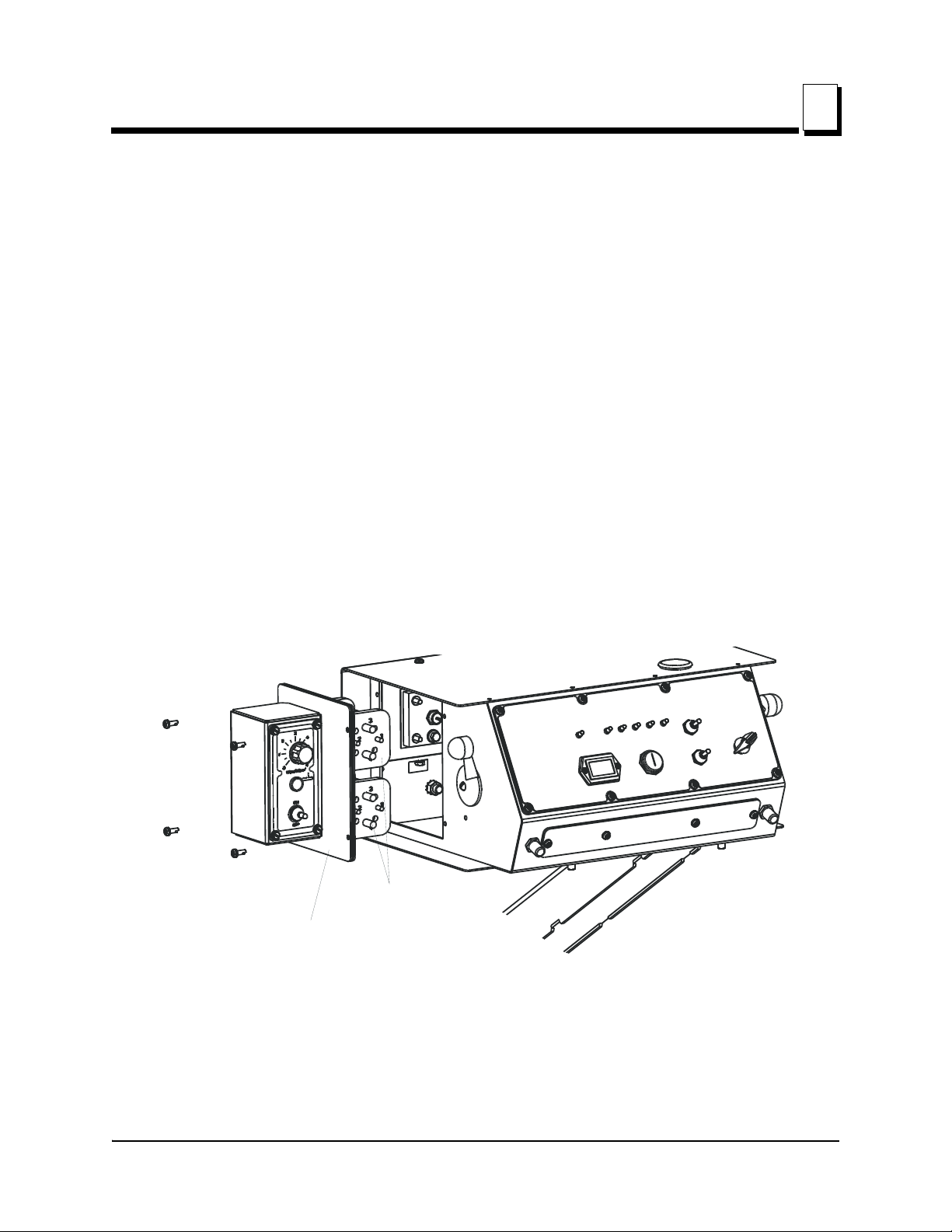
1.1 Control Box Installation .........................................................................1-1
1.2 Control Box Wiring................................................................................1-3
LT30 Super Rev. G9.00+
LT40 Super Rev. H1.00+
LT30HD/40HD Super Rev. H4.00+
LX450 Rev. A1.00+
1.3 Control Box Wiring................................................................................1-4
LT30 Super Rev. F7.00 - G8.00
LT40 Super Rev. F8.00 - G9.00
LT30HD/40HD Super Rev. G1.00 - H3.00
1.4 Control Box Wiring................................................................................1-6
LT30 Rev. F7.00+
LT40 Rev. F8.00+
LT30HD/40HD Rev. G1.00+
1.5 Pump Installation And Wiring (All LT30/LT40 Sawmills)...................1-9
1.6 Pump Installation And Wiring (LX450 Sawmills)...............................1-13
1.7 Water Lube Bottle Conversion and Hose Line Installation (All LT30/LT40 Sawmills)
1-15
1.8 Hose Line Installation (LX450 Sawmills)............................................1-17
1.9 Finishing Steps .....................................................................................1-19
SECTION 2 OPERATION 2-1
2.1 The LubeMizer System ..........................................................................2-1
2.2 Lube Additives .......................................................................................2-3
SECTION 3 MAINTENANCE 3-1
SECTION 4 REPLACEMENT PARTS 4-1
4.1 Pump Assembly (LMS-HP/LMS-A)......................................................4-1
4.2 Pump Assembly (LMS-LX) ...................................................................4-3
4.3 Filter Assembly (LMS-HP/LMS-A).......................................................4-4
4.4 Filter Assembly (LMS-LX)....................................................................4-5
4.5 Blade Guide Block Assembly (LMS-A Only) .......................................4-6
LMS-A Rev. A.01+
4.6 Blade Guide Block Assembly ................................................................4-7
LMS-A Rev. A.00
4.7 Control Box Assembly ...........................................................................4-8
LMS-A Rev A.00+
LMS-RA Rev. E.00+
LMS-LX Rev A.00+
SECTION 5 ELECTRICAL INFORMATION 5-1
5.1 Electrical Components............................................................................5-1
Table of Contents Section-Page
iv WMdoc032619 Table of Contents
5.2 Electrical Wiring Diagram (Control Circuit) .........................................5-2
5.3 Electrical Symbol Diagram ....................................................................5-1
INDEX I
LubeMizer Installation
Control Box Installation
LubeMizer Installation LMS99doc032619 1-1
1
SECTION 1 LUBEMIZER INSTALLATION
1.1 Control Box Installation
1. Raise the saw head to access the battery box. Turn the key to the OFF (#0) position and
remove the key.
2. Remove the two wing nuts and flat washers holding the battery box lid to the battery box.
3. Lift and remove the battery box lid. Remove the negative (-) battery post terminal clamp.
4. Remove the rear panel assembly from the control box.
5. Remove the left control box side panel from the sawmill control box. Remove the two
solenoids from the panel assembly and install them to the provided lube control assem-
bly. Check to ensure that wires are not kinked or pinched. After wiring, the lube control
assembly will be secured in place.
See Figure 1-1.
FIG. 1-1
Lube Control
Assembly
3H0726B
Existing Solenoids
LubeMizer Installation
Control Box Installation
1
1-2 LMS99doc032619 LubeMizer Installation
6. The next step is wiring installation.
See Table 1-1. Refer to the table below for your model mill and the applicable wire
installation section.
Mill Model Revision Wiring Instructions Section
LT30 F7.00+ See Section 1.4
LT40 F8.00+ See Section 1.4
LT30HD/40HD G1.00+ See Section 1.4
LT30 Super
G9.00+ See Section 1.2
F7.00 - G8.00 See Section 1.3
LT40 Super
H1.00+ See Section 1.2
F8.00 - G9.00 See Section 1.3
LT30HD/40HD Super
H4.00+ See Section 1.2
G1.00 - H3.00 See Section 1.3
LX450 A1.00+ See Section 1.2
TABLE 1-1
LubeMizer Installation
Control Box Wiring
LubeMizer Installation LMS99doc032619 1-3
1
1.2 Control Box Wiring
LT30 Super Rev. G9.00+
LT40 Super Rev. H1.00+
LT30HD/40HD Super Rev. H4.00+
LX450 Rev. A1.00+
DANGER! The key switch should still be off, the key
removed and the negative battery cable disconnected as
stated at the beginning of this section. The incoming power
supply of electric-powered sawmills should be discon-
nected and locked out. Failure to do so will result in serious
injury or death.
IMPORTANT! Avoid pinch and pivot points, unnecessary
wire bending and open spaces where the wire could get
caught by a log, etc. If you have any questions, call
Wood-Mizer customer service.
Refer to the appropriate wiring diagram while performing the wiring steps below.
Locate red wire #19 inside the sawmill control box. Disconnect wire #19 from the
red jumper wire connected to the feed drum switch (or terminal #T13 of the wireless
interface on wireless sawmills).
Connect red lube wire #251 to red wire #19. Connect red lube wire #250 to the red
jumper wire.
Locate black wire #20 inside the sawmill control box. Disconnect wire #20 from the
black jumper wire connected to the ground stud at the back of the control box.
Connect blue lube wire #257 to black wire #20. Connect black lube wire #259 to the
black ground jumper wire.
7. Using the existing mounting bolts, install the lube control assembly to the sawmill control
box. Replace the rear control box panel.
STOP! You have completed Control Box
Wiring. Proceed to Section 1.5 Pump
Installation And Wiring (All LT30/LT40
Sawmills) or Section 1.6 Pump Installa-
tion And Wiring (LX450 Sawmills).
LubeMizer Installation
Control Box Wiring
1
1-4 LMS99doc032619 LubeMizer Installation
1.3 Control Box Wiring
LT30 Super Rev. F7.00 - G8.00
LT40 Super Rev. F8.00 - G9.00
LT30HD/40HD Super Rev. G1.00 - H3.00
DANGER! The key switch should still be off, the key
removed and the negative battery cable disconnected as
stated at the beginning of this section. The incoming power
supply of electric-powered sawmills should be discon-
nected and locked out. Failure to do so will result in serious
injury or death.
IMPORTANT! Avoid pinch and pivot points, unnecessary
wire bending and open spaces where the wire could get
caught by a log, etc. If you have any questions, call
Wood-Mizer customer service.
Refer to the appropriate wiring diagram while performing the wiring steps below.
Locate red wire #19 connected to terminal #2 of the power feed drum switch. Cut
wire #19 approximately 5" from terminal #2.
Install a female terminal to the end of the 5" length of wire #19 that remains con-
nected to terminal #2. Install a male terminal to the end of the remaining length of
wire #19.
See Figure 1-2.
Connect red lube wire #250 to the female terminal on the 5" length of wire #19. Con-
nect red lube wire #251 to the male terminal on the remaining length of wire #19.
Locate black wire #20 connected to the ground stud at the rear of the sawmill con-
trol box. Cut wire #20 approximately 5" from the ground stud.
FIG. 1-2
Female Terminal
Male Terminal
3H0761
LubeMizer Installation
Control Box Wiring
LubeMizer Installation LMS99doc032619 1-5
1
Install a female terminal to the end of the 5" length of wire #20 that remains con-
nected to the ground stud. Install a male terminal to the end of the remaining length
of wire #20.
Connect black lube wire #259 to the female terminal to the female terminal on the 5"
length of wire #20. Connect blue lube wire #257 to the male terminal on the remain-
ing length of wire #20.
Using the existing mounting bolts, install the lube control assembly to the sawmill
control box. Replace the rear control box panel.
STOP! You have completed Control Box
Wiring. Proceed to Section 1.5 Pump
Installation And Wiring (All LT30/LT40
Sawmills).
LubeMizer Installation
Control Box Wiring
1
1-6 LMS99doc032619 LubeMizer Installation
1.4 Control Box Wiring
LT30 Rev. F7.00+
LT40 Rev. F8.00+
LT30HD/40HD Rev. G1.00+
DANGER! The key switch should still be off, the key
removed and the negative battery cable disconnected as
stated at the beginning of this section. The incoming power
supply of electric-powered sawmills should be discon-
nected and locked out. Failure to do so will result in serious
injury or death.
IMPORTANT! Avoid pinch and pivot points, unnecessary
wire bending and open spaces where the wire could get
caught by a log, etc. If you have any questions, call
Wood-Mizer customer service.
Refer to the appropriate wiring diagram while performing the wiring steps below.
Locate red wire #19 lying loose in the sawmill control box. NOTE: Install a male con-
nector to the end of wire #19 if one is not already supplied. Connect red lube wire
#251 to red wire #19.
NOTE: If you have installed a water lube solenoid kit (#016141) there will be a fuse-
holder assembly between wire #19 and the #2 drum switch terminal. Unplug the
fuse holder assembly from wire #19 and plug red lube wire #251 in its place. Leave
the assembly wire connected to the #2 drum switch terminal, but cut the wire 5"
from the terminal. Install a female terminal to the end and connect red lube wire
#250 to the female terminal.
Rev. A.00 - A.01: Locate the larger 10-gauge red wire connected to the #2 power
feed drum switch terminal inside the control box. Crimp the supplied yellow T-tap
terminal around the wire. Plug red lube wire #250 into the T-tap terminal.
See Figure 1-3.