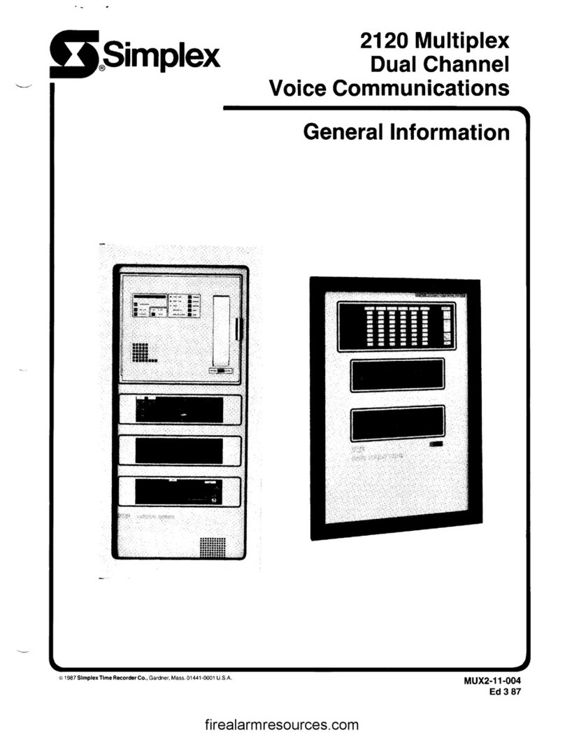
Simplex 2120 Configuration guide

Simplex
2120 Multiplex
Peripherals
General Information T
D 1990 Simplex Time Recorder Co., Gardner, Mass. 01441-0001 U.S.A.
All specifications and other information shown were current as of publication. and are subject to change without notice.
MUX2-1 l-007
Ed690
firealarmresources.com

.
firealarmresources.com

TABLE OF CONTENTS
HOW TO USE THIS PUBLICATION ........................................................... 2
...........................................................
THE ADDS VIEWPOINT CRT/KEYBOARD.. ......................................................................................................... 2
THE ADDS BASIC + CRT/KEYBOARD ............................................................................................................... 5
THE MICRO-TERM CRT/KEYBOARD ................................................................................................................... 7
THE GENICOM TERMINET ................................................................................................................................. 10
THE CENTRONICS 150 ....................................................................................................................................... 13
THE CENTRONICS H80 ...................................................................................................................................... 17
THE CENTRONICS HPC-80 ................................................................................................................................ 21
THE CENTRONICS PS 21O/BROTHER M-1409 .......... ...................................................................................... 22
THE EPSON LX-810 ............................................................................................................................................ 24
1
firealarmresources.com

HOW TO USE THIS PUBLICATION
This publication provides information on the following 2120 Multiplex peripherals:
l
The ADDS Viewpoint CRT/keyboard.
l
The ADDS Basic + CRT/keyboard.
l
The Micro-Term CRT/keyboard
l
The Genicom Terminet (formerly the G.E. TermiNet).
l
The Centronics 150 printer.
l
The Centronics H80 printer.
l
The Centronics HPC-80B printer.
l
The Centronics PS 210 and Brother M-l 409 printers.
l
The Epson LX-81 0 printer.
General service information is provided for each peripheral.
THE ADDS VIEWPOINT CRT/KEYBOARD
The ADDS Viewpoint CRT/keyboard (Figure 1) consists of a green phosphor monitor and a keyboard.
The ADDS CRT/Keyboard
FIGURE 1
Terminals shipped prior to April 1985 are black; those shipped after are white.
ADDS VIEWPOINT KEYBOARD FUNCTIONS
Figure 2 shows the ADDS Viewpoint keyboard. Look at the keys in the numeric keypad on the right. The keys
labeled “Fl”, “F2”, and “F3” perform special functions.
l
Pressing Fl acknowledges 2120 alarms and troubles.
l
Pressing F2 activates the 2120 SIGNAL SILENCE program.
l
Pressing F3 activates the 2120 DETECTOR RESET program.
Note: Fl , F2, and F3 are functional only when the remote acknowledge option is enabled.
l
ESC :
@ # $ % A
& ( i : + - BACK
2 3
4
5 6 7 6 9
zz * SPACE
TAB tQlWlEIRITlYlUlllOlPI f 1 1 :
I t I I t t t t 1 I I L I J t‘
CTRL
LOCK
A
s
D F GHJKL; :’
RETURN
I I I I I I I I I I -
DEL 1 SHFT 1 2 1 X 1 C 1 V 1 B I N I M I r: I ’ I -f
SHIFT
BREAK
The ADDS Viewpoint Keyboard
FIGURE 2
2
firealarmresources.com

Now look at the “CTRL”key on the left side of the keyboard. The “CTRL”key, when used in conjunction with other
keys, also performs special functions.
l
Holding the “CTRL” key down and then pressing the “X” key will end a report that was requested by a
“LIST” command.
l
Holding the “CTRL” key down and then pressing the “A” key will acknowledge 2120 alarms and troubles
(only if remote acknowledge is enabled).
l
Holding the “CTRL” key down and then pressing the “S” key will activate the 2120 SIGNAL SILENCE
program (only if remote acknowledge is enabled).
l
Holding the “CTRL” key down and then pressing the “D” key will activate the 2120 DETECTOR RESET
program (only if remote acknowledge is enabled).
l
Holding the “CTRL” key down and then pressing the “0” key will cause a report being displayed on the
screen to stop scrolling.
l
Holding the “CTRL” key down and then pressing the “P” key will cause a report that has been stopped
by the “CTRL-0” function to proceed.
l
Holding the ‘CTRL” key down and then pressing the “G” key will test the ADDS terminal SONALERT.
ADDS VIEWPOINT OPTION SWITCHES
There are two DIP switch locations on’the ADDS Viewpoint terminal, Sl and S2. Switch package Sl can be seen
from the rear of the ADDS terminal (Figure 3). Switch package S2 is visible only after removing the CRT cover
(Figure 4).
Location of Switch Package Sl
FIGURE 3
J2 (AUX PORT) Jl (MAIN PORT)
II
Location of Switch Package S2
FIGURE 4
3
firealarmresources.com

The first three switches on Sl set the terminal’s baud rate.
BAUD RATE Sl-1 Sl-2 si-3
300 0 0 1
1200 0 1 0
2400 1 0 0
4800 1 0 1
9600 1 1 0
Note: Refer to Figure 3 to determine switch positions for “1s” and “0s”.
Switches 4 through 8 are set as indicated below. Factory switch settings are in bold.
SWITCH NO. SETTING
4 0
1
5 0
1
6 0
1
78 00
01
10
11
FUNCTION
Auto Scroll disabled
Auto scroll enabled
Auto line feed disabled
Auto line feed enabled
Half duplex
Full duplex
Odd parity
Even parity
Marking
Spacing
The switches on switch package S2 are set as below. Factory settings are in bold. Refer to Figure 4 to deter-
mine switch positons for “1 s” and “OS”.
SWITCH NO. SETTING FUNCTION
1
2
3
4
576
7
8
0
Light characters displayed on dark
background.
1 Dark characters displayed on light
background.
0 Parity check disabled.
1 Parity check enabled.
0 60 Hz operation
1 50 Hz operation
**NOT USED**
00 U.S. character set
01 Belgium/France/Azerty
10 Germany/Switzerland
11 U.K./Selectric
0 Steady cursor
1 Blinking Cursor
0 Cursor is a rectangular block.
1 Cursor is an underline.
IMPORTANT: The terminal reads switch settings at power-up. If you change a setting you must turn the terminal
OFF and then ON again for the change to take effect.
Connect the ADDS Viewpoint terminal to the BMUX as indicated in Figure 5.
4
firealarmresources.com

BMUX
BMUX AC INPUT BD RS232 CONNECTOR
TB3 1-1 Jl or J2
PARTS REQUIRED’
(1) 166-075
(6) 474-169 (26-24 AWG)
(6) :7:-226 (16-22 AWG)
(2) 166-076
7 3 2 1 PARTS REQUIRED 7 3 2
(1) 166-075
TO (3) 474-169 (26-24 AWG) TO
ADDS TERMINAL (3) it-226 (16-22 AWG) ADDS TERMINAL
MAIN PORT MAIN PORT
(1) 166-076
, ,
ADDS Terminal-to-BMUX Connections
FIGURE 5
THE ADDS BASIC + CRT/KEYBOARD
The ADDS Basic + CRT/Keyboard (Figure 6) consists of a green phosphor monitor and a keyboard.
The ADDS Basic + CRT/Keyboard
FIGURE 6
ADDS BASIC + KEYBOARD FUNCTIONS
See ADDS VIEWPOINT KEYBOARD FUNCTIONS on page 2.
ADDS BASIC + SETUP MENU
Unlike the previous ADDS Viewpoint CRT/keyboard with option switches, the ADDS Basic+ CRT/keyboard is
menu-driven.
To change operating parameters to those parameters necessary for 2120 Multiplex operation (shown in Figure
7), proceed as follows:
1. Turn ON your ADDS Basic + CRT/keyboard (see Figure 3 for location of ON/OFF switch).
5
firealarmresources.com

2. To display the current Setup Menu on your screen, press CTRL-TAB twice.
l
The current Setup Menu is now displayed on your screen with a blinking cursor positioned at the first field
-Terminal mode. Now you must match the parameters shown in Figure 7.
3. Using SHIFT-Cursor Up or SHIFT-Cursor Down arrow keys, position the cursor at the desired field to be
changed.
Note: Use CTRL-SHIFT-Cursor Up or Cursor Down arrow keys to change screen contrast.
SETUP MENU
1 Terminal mode
4 Baud rate
0 Parity
N Display parity error
Y Full duplex
Y Auto scroll
N Auto line feed
N Light background
N Underline cursor
N Blinking cursor
N Keyclick
N Bell on 73rd column
N 50 Hz operation
0 Language
N Keycap option
N Disable CTRL-2 (3A/3A + only)
N Space advance (3A only)
N Programmable function keys
MODES
0 = Al
1 = A2
2 = 3A
3=3A+
BAUD RATES
0= 110
l= 150
2 = 309
3 = 600
4 = 1200
5 = 1800
6 = 2400
7 = 4800
8 = 9600
9 = 19200
PARITY
0 = Odd
1 = Even
2 = Marking
3 = Spacing
LANGUAGE SELECTION
0 = United States
1 = France
2 = Germany/Switzerland
3 = Sweden/Finland
4 = Denmark/Norway
5 = Spain/Portugal
6 = United Kingdom
l
Cursor UP & DOWN for selection
l
Enter parameter changes
l
HOME saves changes and exits
l
ESC exit without saving changes
l
CTRL-UP & DOWN changes contrast
ADDS Basic+ Setup Menu -
2120 Multiplex Operating Parameters
FIGURE 7
4. Enter Y (yes), N (no), or the appropriate numeric value to match parameters given in Figure 7.
Note: The CTRL key functions listed on page 3 can only be used in the A2 terminal mode.
5. To store new parameters and exit Setup Menu, press SHIFT-HOME keys simultaneously, then release.
Note: a. To restore previous parameters and exit Setup Menu, press the ESC key.
b. To restore default parameters to Setup Menu, press SHIFT-ESC keys simultaneously, then release.
l
DEFAULT PARAMETERS LOADED is displayed at the bottom of your screen. Press CTRL-TAB twice
to see the default values displayed in your Setup Menu.
Connect ADDS Basic + to the BMUX as shown in Figure 5.
firealarmresources.com

THE MICRO-TERM CRT/KEYBOARD
The Micro-Term (Model 425) CRT/Keyboard (Figure 8) consists of a green phosphor monitor and a keyboard.
The Micro-Term CRT/Keyboard
FIGURE 8
MICRO-TERM PROGRAMMING
Follow the instruction manual and use the Set Up key to enter program mode. Select the following:
SET UP DIRECTORY:
SET UP = English, North American Keyboard
DISPLAY SET UP:
80 Columns, Interpret Controls
No Auto Wrap, Jump Scroll, Light Text, Scrn Saver Off Cursor, Block Cursor
GENERAL SET UP:
VDT 100 Mode, VDT 100 ASCII
User Key Unlocked, User Feature Unlocked
Numeric Keyboard Normal Cursor Keys, No New Line
COMMUNICATIONS SET UP:
Transmit = 1200, Receiver = Transmit
No X Off, 8 Bits, No Parity, 1 Stop Bit, No Local Echo EIA Port Data Leads Only, Disconnect 2s Delay, Limited
Transmit
PRINTER SET UP:
Speed = 1200, No Printer To Host
Auto Print Mode, 8 Bits, No Parity, 1 Stop Bit, Print Full Page, ASCII/U.K. Only, No Terminator
7
firealarmresources.com

KEYBOARD SET UP:
Typewriter Keys, Caps Lock
Auto Repeat; No Keyclick; Margin Bell; Warning Bell; Break Auto Answerback; Answerback = center, then CTRL
and B at the same time; Not Concealed.
TAB SET UP:
Does not matter
CUSTOM SET UP:
VDT ID: VDT 100
Compose Key: No-op, 25th Line, Protocol from Host: None
FUNCTION KEYS: (REQUIRES CTRL AND FUNCTION KEY)
SUGGESTIONS:
PROGRAM RESULTS:
CTRL S Return Signal Silence
LIST Return List Status
;[ANY STATEMENT] Return Print any statement (such as
local Phone number, etc.).
;CTRL L (25 ENTRIES)
Return Clears Screen
CTRL X CTRL X HELP Aborts printouts, calls HELP
Return screen, (use for F 15)
CTRL D Detector Reset
TIME Return Calls up time and date
To save data, return to SET-UP Directory, cursor to SAVE, press ENTER, return by pressing SET UP KEY.
The above programming will allow the terminal to be supervised by the 2120. The 2120 port must be set up for
“GE” (or “GE ACK” if acknowledge function is desired). Function keys can be labelled per program if desired.
8
firealarmresources.com

ON
co
165-051
PHONO TO BNC ADAPTER
(SUPPLIED)
COMPOSITE VIDEO OUTPUT
RS232C
CONNECTOR
WITH INTERNAL MOV
SUPPRESSION
(PART OF 733-571)
BRIGHTNESS 1. bmuLL
Y
SEE 733-571 CABLE TERMINATIONS BELOW
CONTROL SUPPLIED
733-571
TO 12OV
40.P”LL
SURGE SUPPRESSED OUTLET 6o “’
ADAPTER. ELECTRICORD
XP CAT. NO. A-1491-l/C-AS
(SUPPLIED)
733471 CABLE TERMINATIONS
If connecting to the RS232 port of a 2120 BMUX: If connecting to TB3 on the ACIO board of a
BMUX:
Red lead (XMIT) to Pin 2 of a DB-25F connector
Black lead (RCV) to Pin 3 of a DB-25F connector
Green lead (GND) to Pin 7 of a DB-25F connector
Cut off the white lead (not used)
Red lead (XMIT) to TB3-11
Black lead (RCV) to TB3-10
Green lead (GND) to TB3-6
Cut off the white (not used)
DB-25F Connector Pin Layout
1 Back View 13 Front View
13 1
firealarmresources.com

THE GENICOM TERMINET
Note: The Genicom TermiNet was previously manufactured by General Electric.
The Genicom TermiNet (Figure 9) is a keyboard/printer that functions in much the same way as the ADDS
terminal.
The Genicom TermiNet
FIGURE 9
INSTALLATION NOTES
The Genicom TermiNet can be supervised by the BMUX. To supervise a TermiNet, the BMUX polls it every nine
seconds. The TermiNet (if functioning properly) responds with special answerback message that says, “Yes, I’m
still here”. The lack of an answerback causes the BMUX to report a trouble for the TermiNet’s port. The BMUX
will report a port trouble under any of the following conditions:
l
The TermiNet has failed.
l
The Terminet has been turned off.
l
The TermiNet’s RS232C cable has been disconnected.
Note: It is not necessary to supervise the TermiNet.
IMPORTANT: The TermiNet must be connected to its order entry-assigned port on a COLD START if it is to be
supervised or a port failure will be reported.
If the G.E. TermiNet does not respond properly when connected to a supervised 2120 port, reset the BMUX using
the CPU board switch. When you do so the TermiNet must be powered-up, on line, and connected to the BMUX.
Further, the appropriate port must be designated “GE.”
If after trying the above the TermiNet does not respond properly, follow the procedure below.
Note: Make sure that AC is present at the unit, that its paper is loaded, and that it is connected to the BMUX
before proceeding.
1. Hold down the [=I key and press the
q
key. The unit’s display should indicate the port’s
baud rate. If not, holding down the I FCT key and repeatedly pressing the El ( key will
cause the available baud rates to appear in the display. Stop at the appropriate baud rate.
10 =lOO baud 30 = 300 baud 120 = 1200 baud
2. Hold down the El
FCT key and press the I7
( 9 key until the display indicates “8.” (This sets
the number of lines per inch.)
3. Hold down the I FCT key and press the IK] key until the display indicates “FUL.” (This sets the
unit’s mode to full duplex.)
4. Hold down the pEq key and press the m key until the display indicates “OnL.” (This puts the
, unit on line.)
10
firealarmresources.com

5. Hold down the [FCTl key and press the I
h 2 key until the display indicates “16.” (This sets
the number of characters per inch.)
6. Enter “DEV” at the local printer ot verify that the TermiNet’s port is designated “GE.” If not, reassign the
port.
7. If you now get a port failure, reset the BMUX via the CPU board switch. (When doing so make sure that
the TermiNet is powered up, on line, and connected to the BMUX.)
Note: If the port failure does not clear within 60 seconds, then proceed to Step 8. If the port failure clears, then
you are done.
8. Hold down the pj key and press the m key until the display indicates “LOC.” (This puts
the unit into local operation.)
9. Hold down the Ei key and type in “ASU.” The TermiNet should then print “9 B.” (This checks the
unit’s response to a BMUX poll.)
Note: If the result of Step 9 is something other than “q B,” then proceed to Step 10. If the result is correct,
10.
11.
12.
13.
14.
15.
16.
17.
then proceed to Step 14.
Press and release the El
FCT key.
Hold down the I CTL key and press the [BI key.
Press and release the [FCT 1 key.
Repeat Step 9 to verify your entry. If the result is not ” 9 B,” then go to Step 16.
Press the [RETURNI key
You are done. To bring the TermiNet back on line, repeat Step 4. Then, reset the BMUX via the switch
on the CPU board.
Hold down the I FCT key and type in “OSU.” The resulting printout must look like this:
123456789012345678901234567890
000000000000000000000000000000
If the printout is correct, then press the [ RETURN 1 key.
If an “I” appears under any number, move the print head to the location of the “I” and type in a capital “0”.
Do so for each “I” in the printout. Press the [] key when done.
Go to Step 15.
TERMINET KEYBOARD FUNCTIONS
Figure 10 shows the TermiNet Keyboard.
FCT ESC ! , ‘8 (
1 91) ,.,I r I+_I~IDELJRPTI
The TermiNet Keyboard
FIGURE 10
11
firealarmresources.com

Look at the “CTL” key on the left side of the keyboard. The “CTL” key, when used in conjunction with other keys,
performs special functions.
l
Holding the “CTL” key down and then pressing the “X” key will end a report that was requested by a “LIST”
command.
l
Holding the “CTL” key down and then pressing the “A” key will acknowledge 2120 alarms and troubles. (If
the port is programmed for remote acknowledge.)
l
Holding the “CTL” key down and then pressing the “S” key will activate the 2120 SIGNAL SILENCE program.
(If the port is programmed for remote acknowledge.)
l
Holding the “CTL” key down and then pressing the “D” key will activate the 2120 DETECTOR RESET
program. (If the port is programmed for remote acknowledge.)
l
Holding the “CTL” key down and then pressing the “G” key will test the TermiNet’s SONALERT.
How to Set TermiNet Margins:
1. Hold down the 0
FCT key and press the r\ key. This clears the existing margins.
2. Return the print head to the left margin by pressing the 1 RETURN 1 key.
3. Position the print head at the desired left margin location using the space bar.
4. Hold down the El
FCT key and press the [3] key. This programs the left margin setting at the
print head’s location.
5. Position the print head at the desired right margin location using the space bar.
6. Hold down the ml key and press the 171 key. This programs the right margin setting at the
print head’s location.
How to Set Top of Form (TOF) and Bottom of Form (BOF)
1. Place the paper into the TermiNet and align the desired top-of-form location with the print head’s position.
2. Hold down the ilFCT key and press the [o] key. This programs the TOF at the print head’s
current location. (Display reads, “FSU.“)
3. Using the
LF
I
key, advance the paper until the bottom-of-form location is at the print head’s position.
4. Hold down the 0FCT key and press the [y] key. This programs the BOF at the print head’s
current location.
5. Using the cl
LF key, advance the paper until the print head is at the top of the next page.
6. Hold down the 0FCT key and press the 101 key. This terminates the form’s set up mode.
Note: There are two TermiNet versions. The 2030 operates at 300 baud only; the 2120 operates at 1200 baud.
Connect the TermiNet to the BMUX as shown in Figure 11.
BMUX AC INPUT BD RS232 CONNECTOR
Jl or J2
PARTS REQUIRED
(1) 166-075
(6) 474-169 (26-24 AWG)
OR
(6) 474-226 (16-22 AWG)
(2) 166-076
7 3 2 * PARTS REQUIRED
(1) 166-074
(3) 474-169 (26-24 AWG)
TO TERMINET (3) %-227(16-22 AWG) TO TERMINET
(1) 166076
TermiNet-to-BMUX Connections
FIGURE 11
12
firealarmresources.com

THE CENTRONICS 150
The Centronics 150 (Figure 12) is a printer that provides hard copy of 2120 status reports.
The Centronics 150 Printer
FIGURE 12
Note: The Centronics 150 was available prior to the third quarter of 1985.
CENTRONICS 150 CONTROL PANEL FUNCTIONS
Figure 13 shows the Centronics 150 control panel and on/off switch. There are three LEDs and two switches on
the control panel.
l
The SELECT switch and its associated green LED. Pressing the SELECT switch will enable the printer for
printing (SELECT LED on). If the printer is disabled, then the LED will be off.
l
The red P.E. (Paper Empty) LED. The LED will be ON when there is no paper in the printer. If the printer
is enabled and the paper runs out, then the printer will be automatically disabled.
l
The green POWER LED, which is on to indicate the presence of AC.
l
The T.O.F. switch. Pressing this switch causes the printer to advance the paper by the number of lines
selected via internal option switches. We’ll discuss the option switches momentarily.
ON/OFF
SWITCH
SELECT
SWITCH
/ i.0.F.
Py;;R SWITCH
Centronics 150 Control Panel
FIGURE 13
13
firealarmresources.com

The SELECT switch performs another function that could be useful at system checkout. If the printer is off and
you turn it on with the SELECT switch pressed, then the printer will perform a self-test. A sample self-test printout
is shown in Figure 14. To end the self-test, turn the printer off.
! “#gi%‘&> () s+, --.
/tjl234!fi&,78’q: j cl=): ‘@ABCDEFGHIJKLMNOPWRSTUVWXYZC\l~~.-~~.tlc~efg~li jklmnop
“#$.Y.&’ ():t:+,-. /012.34.%7w: ;<=:>’ ‘@ABCUEFGHIJKLMNOPQRS’TUVWXYZC\l”-(abcdef.3hi jklmnors
#$y& () :*+t -. /01234567pT: ; (=>: “CCARCDEFGH I JKLMNOFC!RSTUVW XY Z C\ 3*<- ( nbcdefrhi jklmno~qr
By;&’ ( j *+> -. /(j 12345&7:39 : ; .::= >‘?(IABCt~EFGHI JKLMNUPBRSTUVWXY Z C\ I’..- ( abcdefsh i jklmnoPqr5
%&’ ( j :t:+, -. /Cl1 345&789: ; (=>?@~EC[W%HI JKLMNOPBRSTUVWXYZ [ \ J”- ( ntlcde f9h i j 1::1mnopqr s t
&‘()*:+,-. /(j12345&78’?: ; ~:=>‘?‘C~ABI~DEFI~HI,JKLMNUF~R!~T~-IVWXYZ[ \ ]“-’ abcdefsl-i i jklmnoPsrstw
) () :t:+:. -. /(:)12345&789: ; (=>?
@!ABCTSEFGHIJKLMNOFBRSTUVWXYZ C\ I”.- (
abcdefshi jklmnoFqrstuv
( ) :++.. -. /(> 12.3456789: ; i: =>‘?@ABCDEFl;H 1JKLMNi:ipi’R!sTl-IVWXYZ [ \ ]“- ( abcdefsh i jklmnorqrstuvw
j*+>-. /0123456789: : (=>~~ABCDEFGHI.JKLMNOPaRSTUVWXYZ C\ I”- ( abcde f9h i j 1::1mnapqr s t uvwx
:*+> -, /(312.345/:.7:39: ; (= >?@AEiCDEFl3HI .JKLMNOFQR!~Tl-IVWXYZ [ \ I.“.- ( abcdeflh i jklmnoFqrstuvuxr
+>-. /01234%78’?: ; C=>?@ABCDEFGHI JKU’W~FQRSTl-lVWXYZ[ \ 1*x-C s.tlcde fqh i j k 1
mrlopqps t IJVI~IXYZ
>- , /(j 12345/,7:39 : 3.:::= >?@ABCDEFGH I JKLMNI~FI~R!~TUVWXYZ C\ ] “- 5abrdef3h i jklmnorqrstuvwxrzC
-. /01234%789: ; (=~?‘@f$~~~~Ef=~+iI JKLMNOFQK!~Tl-lVWXYZ [ \I”-’ abcdefrh i jklmnoFsrstuvwxrz( I
. /(jl2345&,7:39: ; .<:z::,‘?
‘MBCDEFGH
I JKLMNUFQR!3TUVWXY Z C\ I^- ( a.bcdefrh i jklmnoFsrstuvwxrzi I ::.
/(j 12345&7@‘;,: ; .:I= >’
:‘@ABCDEFGHI
JKLMNOFQRSTUVWXYZ C\ I”- ( abcdefsh i jklmnopqrstuvwxrz.~ I ::.’
012.3456789: ;.:::=>?~ABl~DEFl~HI JKLMNl~lF8RSTI_lVWXYZC\].~-~ abl:def.gh i
jklmnoFq,~stuvwxrz.:: ) )”
1234!%7:3”): ; (= >‘?@fiBl:DEFGH 1JC::LMNOFQRSTl-IVWXYZ [ \ ] +.- ( abcdefshi jklmnoFqrstuvwxrz~: I >” !
2.34567:39: ; < =:>‘?@ABC[tEFGH 1,JKLMNl~tFl~!RSTl~VWXYZ [ \ ] .“‘,_( nbcdefvh i jklmnorsrstuvwxrz( I I:-+ ! ”
Centronics 150 Self-Test Printout
FIGURE 14
CENTRONICS 150 OPTION SWITCHES
There are two DIP switch locations on the Centronics 150 printer. The parity/forms length DIP switches are located
beneath the control panel (Figure 15). The baud rate DIP switches can only be accessed by removing the printer
cover (Figure 16). Figure 17 illustrates the location of the baud rate DIP switches.
ODD
7 BIT DATA/8 BIT DATA
PARITY/EVEN PARIT ENABLE PARITY
Location of Parity/Forms Length DIP Switches
FIGURE 15
14
firealarmresources.com

FRONT COVER
,REAR COVER
CAUTION: Remove Dower
BAUD RATE
DIP SWITCHES
ON REAR OF THIS
LOGIC BOARD
cover.
LOWER COVER
Cover Removal
FIGURE 16
Location of Baud Rate DIP Switches
FIGURE 17
15
firealarmresources.com

The parity/forms length DIP switches are set as indicated below. Factory settings are indicated in bold.
SWITCH NO. SElTlNG FUNCTION
1 ON 7-bit data
OFF 8-bit data
2 ON Odd parity
OFF Even parity
3 ON Disable parity
OFF Enable parity
4 ON Forms length = 8 inches
5 ON Forms length = 4 inches
6 ON Forms length = 2 inches
7 ON Forms length = 1 inch
8 ON Forms length = % inch
l
Switches 4 through 8 are normally off, giving a forms length of 11”.
Connect the printer to the BMUX as shown in Figure 18. (Normally, the Centronics 150 printer is run at 300 baud,
or at 1200 baud with the handshake line connected.)
BMUX AC INPUT SD BMUX
(TERMINAL BLOCK) (RS232 CONNECTORI
I I I I
TB3
2
HANDSHAKE
-t 11
6 10
(2) 166-076
(6) 474-169 (28-24 AWG)
(6) ,9”,228 (18-22 AWG)
(1) 166-078 SHELL
7 3 ~‘““‘” REo’Dw
(1) 166-075
Ch
11
I
TO CENTRONICS 160 (3) 474-169 (28-24 AWG) TO CENTRONICS 160
PRINTER I (3) :7:-228 (18-22 AWG) 1 PRINTER
1 I
(1) 166-078SHELL 1
Centronics Printer-to-BMUX Connections
FIGURE 18
HANDSHAKE
1
16
firealarmresources.com

.
If you wish to temporarily connect the Centronics 150 printer to the ADDS CRT/keyboard AUX port for service
printouts, etc., do so using Figure 19.
NOTES
does not seem to function, you can enable it by holding down the
key. To disable the port once enabled by CTRL-R, hold down the
(CTRL( key and press the m key.
2. Do not use the ADDS CRT/keyboard AUX port for permanent connections because the AUX port must be
enabled by a CTRL-R anytime the ADDS CRT/keyboard is powered-up.
ADDS AUX PORT
(6) ;::;:f: 577 s’E
(2) 166-075
(6)
474-228 (18-22 AWG)
(1)
166-078 SHELL
(1)
(3)
(3)
(1)
PARTS REQ’D
166-075
474-169 (28-24 AWG)
OR
474-228 (18-22 AWG)
166-078 SHELL
“handshake” line to TB3-2 on the
3 7 11
2120 BMUX.
TO CENTRONICS 150
PRINTER
Note: Unless running the printer at
300 baud, you must connect this
Centronics Printer-to-ADDS Aux Port
Connections
FIGURE 19
THE CENTRONICS H80
The Centronics H80 (Figure 20) is a printer that provides a hard copy of 2120 status reports.
The Centronics H80 Printer
FIGURE 20
Note: The Centronics H80 printer replaced the Centronics 150 printer.
17
firealarmresources.com

CENTRONICS H80 CONTROL PANEL FUNCTIONS
Figure 21 shows the Centronics H80 control panel. There are three LEDs and three switches on the control panel.
l
The FF switch, which advances the printer paper to the top of the next page when pressed.
l
The LF switch, which advances the printer paper by one line when pressed momentarily, and feeds paper
continuously if held in when the printer is OFF LINE.
l
The ON LINE switch. When power is turned on, the printer is automatically on line and ready to receive data.
If you press this switch, the printer is placed OFF LINE, allowing local paper control via LF and FF. Pressing
it once more places the printer ON LINE.
l
The ON LINE LED, which indicates that the printer is ON LINE and ready to receive data.
l
The ALARM LED, which indicates that the printer is out of paper
l
The READ,Y LED, which is on to indicate that the printer is on.
Centronics H80 Control Panel
FIGURE 21
The LF switch performs another function that could be useful at system checkout. If the printer is off and you turn
it on with the LF switch pressed, then the printer will perform a self-test. (Be sure to leave the LF switch pressed
for a few seconds after applying power.) A sample self-test printout is shown in Figure 22.
!“#8%t’O++,-./C~1234567B9::~=.~?~ABCDEFGHIJKLMNOPORSTUVWXYZC\l* ‘abcdefghijklmno
!“#B%f’o*+,-. /U123456789:;~=>?~ABCDEFGHIJKLMNOPORSTUVWXYZC\l~ ‘abcdefghijklmnop
“I)$%&’ o*+,-. /0123456789: ; <=>?@AHCDEFGHIJKLMNOPORSTUVWXYZ C\ I” ‘;abcdef ghi j klmnopq
#$%~‘O++,~./0123456789:;~=:~?~ARCDEFGHIJ~~LMNOPORSTUVWXYZ~\l~~ ‘abcdefghijklmnopqr
8X& o*+,-. /0123456789:;<=>?@ABCDEFGHIJKLMNOPORSTUVWXYZt\l~ ~abcdefghijkImnopqrs
%&’ o*+,-. /O123456789:;<=>?@ABCDEFGHIJKLNNOPORSTUVWXYZC\l* ‘abcdef ghi jklmnopqrst
&’ o*+,-. /0123456789::C=>?@ABCDEFGHIJKLMNOPORSTUVWXYZ~\l* rabcdefghijklmnopqrstu
* () t+, -. /oi23456789: ; ~=>?@ABcDEFGHIJKLMN~PORSTUVWXYZC\ 13%‘abcdefghi jklmnopqrstuv
o*+,-. /0123456789:;~=>?4ABCDEFGHIJELMNOPORSTUVWXYZC\l~ ?abcdefghijklmnopqrstuvw
)++,-./0123456789:;~=~?~ABCDEFGHIJKLMNOPORSTUVWXYZC\l* ‘abcdefghi jklmnopqrstuvwx
l +, -.
/0123456789: ; <=>?@ABCDEFGHIJKLHNOPORSTUVWXYZC\ I* Fabcdef ghi j klmnopqrstuvwxy
+ - /O123456789:;<=>‘?@ABCDEFGHIJKLMNOPQRSTUVWXYZt\l*
1.;0123456789::<=>~~ABCDEFGHIJKLMNDPORSTUVWXYZC\l~~ -abcdefghi jklmnopqt-stuvwxyz
‘./Ol23456789:;~=>?~ABCDEFGHIJKLMNOPORSTUVWXYZC\l~ Fabcdef ghi j kl mnopqrstuvwxyz {
?abcdefghi jklmnopqrstuvweyz(l
./C~123456789::<=>?@ABCDEFGHIJKLNNOPORSTUVWXYZ~\l~
/0123456789:;~=>?@ABCDEFGHIJKLNNOPORSTUVWXYZC\l* ;Bbcdef ghi j klmnopqrstuvwcyz ( : 1
‘abcdefghi jklmnopqrstuvwxy=C :>”
0l23456789:;C=>?@ABCDEFGHIJKLMNOPORSTUVWXYZ~\l” rabcdefghijklmnopqrstuvwxyzC :>*a
~~~~~~~I~~:;<=>?@ABCDEFGHIJKLI~NOPORSTUVWXYZC\~~ -abcdef ghi jklmnopqrstuvwxyz <: >-a&
234567B9:;<=~?~ABCDEFGHIJKLHNOPORSTUVWXYZ~\l” Tabcdef ghi j klmnopqrstuvwxyz { i >‘“&&ti
3456789:
; (= >.?d
CABCDEFGHIJKLMNOPORSTUVWXYZC\3^ ‘abcdefghi jklmnopqrstuvweyzC :l”a&(ic5
456789:;<=>?@ABCDEFGHIJKLMNOPRRSTUVWXYZ~\l~
56789::C=>?4ABCDEFGHIJKLHNOPQRSTUVWXYZC\l~~~ rabcdef ghi j klmnopqrstuvwxyz CI >“&2tbi
abcdef ghi j klmnopqrstuvwxyz C: l”&Pbi ’
Centronics H80 Self-Test Printout
FIGURE 22
18
firealarmresources.com
Other manuals for 2120
8
Table of contents
Other Simplex Industrial Equipment manuals

Simplex
Simplex LT0290 User manual

Simplex
Simplex 4090-9006 User guide

Simplex
Simplex 4604-9201 Quick guide

Simplex
Simplex VSH SUPER Manual

Simplex
Simplex Full-Size Fuelport User manual

Simplex
Simplex Trident User manual

Simplex
Simplex LBD Series User manual

Simplex
Simplex STS User manual

Simplex
Simplex 2120 Configuration guide

Simplex
Simplex STS DAY TANK User manual