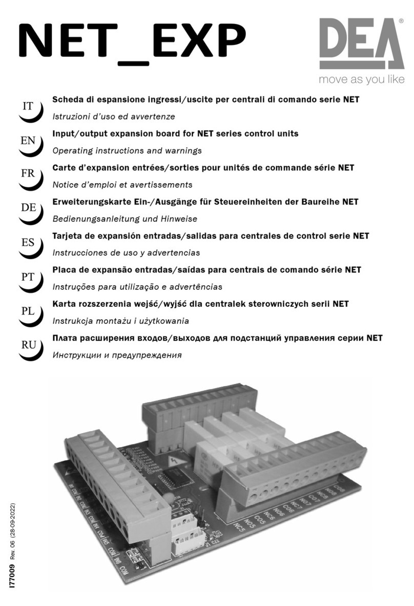
GCI E84 User manual

GCI E84 Emulator
Getting Started
Version 2.4a


GCI E84 Emulator Getting Started Manual Version 2.4a
GCI E84 Emulator Getting Started Manual i
Table of Contents
Overview ...................................................................................................................................................... 1
Getting Started ............................................................................................................................................ 1
Minimum System Requirements .................................................................................................... 1
E84 Emulator Package Contents ................................................................................................... 1
E84 Emulator Power Requirements ............................................................................................... 1
Installation ...................................................................................................................................... 2
Uninstalling the E84 Emulator Application ..................................................................................... 3
PC to E84 Emulator Connection .................................................................................................... 3
Connecting to USB ............................................................................................................ 3
Powering Up the E84 Emulator ......................................................................................... 3
Connection Status Indicator .............................................................................................. 4
Using Optical Transceivers ............................................................................................... 4
E84 Handoff Modes ..................................................................................................................................... 5
Single Handoff Mode ...................................................................................................................... 5
Simultaneous Handoff Mode .......................................................................................................... 5
Continuous Handoff Mode .............................................................................................................. 6
Using the E84 Emulator GUI ....................................................................................................................... 7
Main Menu ...................................................................................................................................... 7
Automated Test Setup Screens ..................................................................................................... 7
Select Default Tests Button ............................................................................................... 8
Select Unload Port Tests Button ....................................................................................... 8
De-Select All Tests Button ................................................................................................ 8
Test Setup Option Buttons ................................................................................................ 8
Continuous Handoff Test Setup Screen ......................................................................................... 9
Defining the Continuous Mode Test Sequence List .......................................................... 9
SELECTED CYCLES List .......................................................................................... 9
AVAILABLE CYCLES List .......................................................................................... 9
Add / Remove Buttons ......................................................................................... 9
Clear List Button ................................................................................................. 10
Cycle Sorting Buttons ......................................................................................... 10
Default Cycles Buttons ....................................................................................... 10
Test Setup Option Buttons .............................................................................................. 10
Automated Test Screens .............................................................................................................. 11
Operator Action Required Screen ................................................................................... 11
Default Timer Settings Screen ........................................................................................ 12
Operator Prompted Pass / Fail Screen ........................................................................... 12
Test NOTES Field ............................................................................................................. 12
Automated Testing Completed Screen ........................................................................................ 13
Manual Control Screens ............................................................................................................... 13
Test Plans ................................................................................................................................................. 13
E84 Emulator Connector Pinout ................................................................................................... 13
Version History ............................................................................................................................. 14
Version 2.4a .................................................................................................................... 14
Version 2.3 ...................................................................................................................... 14
Version 2.2a .................................................................................................................... 14
Version 2.2 ...................................................................................................................... 14
Version 2.1.1 ................................................................................................................... 14
Technical Support ........................................................................................................................ 15

GCI E84 Emulator Getting Started Manual Version 2.4a
GCI E84 Emulator Getting Started Manual ii
List of Figures
Connection Error Message .......................................................................................................................... 2
USB Cable Connection ................................................................................................................................ 3
Found New Hardware Message .................................................................................................................. 3
E84 Emulator Main Menu ............................................................................................................................ 4
Optical Transceiver connects to the Emulator as Passive Equipment Female DB-25 connector ........... 4
Example Single Handoff Mode Transfer ...................................................................................................... 5
Example Simultaneous Handoff Mode Transfer .......................................................................................... 5
Example Continuous Handoff Mode Transfer ............................................................................................. 6
Main Menu ................................................................................................................................................... 7
Automated Active Mode Test Setup Screen ............................................................................................... 7
Continuous Mode Test Setup Screen ......................................................................................................... 9
Automated Active Mode Test Screen ........................................................................................................ 11
Operator Action Required Screen ............................................................................................................. 11
Default Timer Settings Screen .................................................................................................................. 12
Timer Test Pass/Fail Screen ..................................................................................................................... 12
Active Testing Completed Screen ............................................................................................................. 13
Active Mode Manual Control Screen ......................................................................................................... 13

GCI E84 Emulator Getting Started Manual Version 2.4a
GCI E84 Emulator Getting Started Manual 1
Overview
The E84 Emulator provides an automated method to test the active and passive E84 interfaces on
semiconductor processing equipment. The emulator utilizes a software based platform that runs on a PC
running Windows XP, 7, or 10 operating systems. This software provides the graphical user interface
(GUI) and the control algorithms. The E84 Emulator provides the hardware required to interface with the
active or passive process equipment. The E84 Emulator interfaces with the laptop computers USB port.
The E84 Emulator performs automated E84 interface testing following pre-defined industry standard test
plans. These test plans provide a means of verifying the E84 compliance of both active and passive
process equipment. All defined handoff sequences are supported, including Single, Simultaneous and
Continuous modes.
E84 Emulator Application Version 2.4a requires a USB Interface E84 Emulator whose hardware has been
updated to version 1.3. Older versions of the E84 Emulator, both USB and Parallel Port versions, are not
compatible. Contact GCI Support ([email protected]) for hardware upgrade pricing.
Getting Started
Minimum System Requirements
The E84 Emulator Application requires the following minimum system configuration:
• Windows XP, 7, or 10 operating system.
• One USB port for the USB Interface version.
• 40 MB of available hard disk space.
E84 Emulator Package Contents
The E84 Emulator package includes the following:
• The E84 Emulator Application installation CD-ROM.
• The E84 Emulator.
• 1 - 15', male-to-female, 25-pin, straight-through interface cable (connects the E84 Emulator to
the process equipment under test).
• 1 - 6' power cable.
• 1 - USB Cable (for the USB Interface version).
• Printed Getting Started manual.
E84 Emulator Power Requirements
• 110 to 220 VAC 50 - 60 Hz (see rear panel).

GCI E84 Emulator Getting Started Manual Version 2.4a
GCI E84 Emulator Getting Started Manual 2
Connection Error Message
Installation
To install the E84 Emulator Application, run the GCI_E84EmulatorSetup2.4a.exe program from the
E84 Emulator Installation CD.
The installer is also available on-line at:
www.getcontrol.com/downloads/GCI_E84EmulatorSetup2.4a.exe
Follow the on-screen instructions, selecting the destination directory. GCI recommends accepting the
default directory. Selecting a directory within the C:\Program Files or C:\Program Files (x86) directory
structure is not recommended and may cause unexpected application behavior.
When installation is complete, a dialog box is displayed indicating the completion of the installation. You
must re-boot your system before using the E84 Emulator Application.
The setup program will add a shortcut to the E84 Emulator Application to your Start Menu. Use this
shortcut to start the E84 Emulator Application.
If, when starting the E84 Emulator GUI, you receive an error message of the form:
the E84 Emulator Application has failed to connect to the E84 Emulator hardware.
Check that the USB cable is properly connected and the Emulator has power.

GCI E84 Emulator Getting Started Manual Version 2.4a
GCI E84 Emulator Getting Started Manual 3
USB Cable Connection
Found New Hardware Message
Uninstalling the E84 Emulator Application
The E84 Emulator Installation program adds a shortcut to an uninstall program that will completely
remove the E84 Emulator Application from your system. If it becomes necessary to remove the
Application, simply click on the Uninstall shortcut and follow the on-screen instructions.
PC to E84 Emulator Connection
Connecting to USB
Connect the E84 Emulator to a PC USB Port and turn Emulator on before running the E84 Emulator
Application.
Connect the provided USB cable into a USB Port on the
PC and to the USB Port on the E84 Emulator as shown.
The USB Port is located on the back panel next to the
AC power input module. It is labeled PC INTERFACE.
Powering Up the E84 Emulator
Plug the provided standard power cord into the E84
Emulator and into a 100V - 240V AC wall outlet. Turn
the power switch on. The power switch is located on the
power input module.
The top of the E84 Emulator has cut-outs showing a
series of status LEDs. Make sure the two green power LEDs are both illuminated (+24V and +5V). If
either of these LEDs are not illuminated when the E84 Emulator is connected to a known good AC power
source (and the power switch is in the ON position), there may be a problem with the power supply in the
unit.
The first time the USB Interface E84 Emulator is
turned on, Windows will display a brief message
indicating that it has found new hardware. The
E84 Emulator utilizes the Human Interface Device
(HID) Class of USB drivers. Windows XP, 7 and
10 all provide a default HID Class Driver. It is not
necessary to install any additional drivers. Note,
this message only appears the first time you start
up the E84 Emulator.

GCI E84 Emulator Getting Started Manual Version 2.4a
GCI E84 Emulator Getting Started Manual 4
E84 Emulator Main Menu
Optical Transceiver connects to the Emulator as
Passive Equipment Female DB-25 connector
Plug an E84 compatible optical transceiver
into the female DB-25 port on the E84
Emulator labeled Emulator as Passive
Equipment as shown. With an optical
transceiver connected in this way, the E84
Emulator Application can run both Active
and Passive mode tests.
Do not attempt to install a gender changer
between the optical transceiver and the
E84 Emulator. Connecting the optical
transceiver to the male DB-25 port labeled
Emulator as Active Equipment using a
gender changer will not work.
Connection Status Indicator
Launch the E84 Emulator Application from the
shortcut in the Startup menu. The Main Menu
will be displayed, and all option buttons are
enabled as shown.
The Communications status is displayed in the
lower left of the Main Menu. It will display
Communications Mode - USB when the E84
Emulator Application is properly
communicating with the E84 Emulator USB
Interface.
When the user attempts to use any of the four
test buttons, the E84 Emulator Application
attempts to communicate with the E84
Emulator. With communication established,
testing continues normally. If the E84
Emulator Application cannot communicate
with the E84 Emulator, a Communication Error Message will be displayed, and testing will be disabled.
Using Optical Transceivers
The Get Control E84 Emulator is shipped with a 15' connecting cable used for hardwired E84 emulation.
The E84 Emulator is compatible with all E84 compatible Optical Transceivers. GCI produces several
optical transceivers that can be used with the E84 Emulator.
P/N GCI04002 - GCI E84 Optical Transceiver (available in 2 and 5 meter cable lengths)
P/N GCI04100 - GCI RJ-11 E84 Optical Transceiver (with data logging)
Optical transceivers from GCI are compatible as shipped. Other optical transceivers must first be properly
terminated with a male DB-25 connector, according to the E84 specification.

GCI E84 Emulator Getting Started Manual Version 2.4a
GCI E84 Emulator Getting Started Manual 5
To Zoom In: Right-Click and drag to select Zoom Win dow
10:30:54 - 09/25/2000
Recorded E84 Signals
Test Area : Get Control, Inc. Ref Voltage : 1.8 Volts
Tested By : AJG Load Port # :
Active Eq. Mfg : Get Control, Inc. Passive Eq. Mfg : Get Control, Inc.
Active Eq. Model : E84 Emulator 1 Passive Eq. Model : E84 Emulator 2
TA1 - TA3 : 2, 2, 2 TP1 - TP5 : 2, 2, 60, 60, 2
Time Signal St
------------ ------ --
03.853 CS_0 1
03.991 VALID 1
05.788 L_REQ 1
05.990 TR_REQ 1
06.653 READY 1
06.897 BUSY 1
35.881 L_REQ 0
36.086 BUSY 0
36.152 TR_REQ 0
36.287 COMPT 1
36.829 READY 0
37.054 COMPT 0
37.154 VALID 0
37.254 CS_0 0
0 10 20 30 40 50
Single Handoff Example
L_REQ
U_REQ
READY
CS_0
CS_1
VALID
TR_REQ
BUSY
COMPT
CONT
HO_AVBL
ES
Example Single Handoff Mode Transfer
To Zoom In: Right-Click and drag to select Zoom Win dow
10:35:03 - 09/25/2000
Recorded E84 Signals
Test Area : Get Control, Inc. Ref Voltage : 1.8 Volts
Tested By : AJG Load Port # :
Active Eq. Mfg : Get Control, Inc. Passive Eq. Mfg : Get Control, Inc.
Active Eq. Model : E84 Emulator 1 Passive Eq. Model : E84 Emulator 2
TA1 - TA3 : 2, 2, 2 TP1 - TP5 : 2, 2, 60, 60, 2
Time Signal St
------------ ------ --
03.273 CS_0 1
03.273 CS_1 1
03.411 VALID 1
04.865 L_REQ 1
05.115 TR_REQ 1
05.756 READY 1
06.021 BUSY 1
40.282 L_REQ 0
40.508 BUSY 0
40.550 TR_REQ 0
40.692 COMPT 1
41.067 READY 0
41.251 COMPT 0
41.352 VALID 0
41.452 CS_0 0
41.452 CS_1 0
0 10 20 30 40 50
Simultaneous Handoff Example
L_REQ
U_REQ
READY
CS_0
CS_1
VALID
TR_REQ
BUSY
COMPT
CONT
HO_AVBL
ES
Example Simultaneous Handoff Mode Transfer
E84 Handoff Modes
The SEMI® E84 Specification defines three types of handoff modes, Single, Simultaneous, and
Continuous. The E84 Emulator supports all three handoff modes. This section briefly describes each
mode, and explains the associated testing capabilities of the E84 Emulator.
Single Handoff Mode
Single Handoff Mode is used to transfer a single carrier to or from a Load Port. The AMHS equipment
defines the target Load Port at the beginning of the handoff sequence, using one of the Load Port select
signals (CS_0, CS_1). Only one of the two signals is activated during the handoff sequence.
The figure at right shows E84 interface signals recorded
during a typical Single Handoff Mode transfer. The
timing diagram shows the CS_0 signal turning ON to
indicate a Single Handoff Mode transfer.
The E84 Emulator Application provides 17 active
mode tests (Emulator acts as the active equipment) that
can be run using Single Handoff Mode. These tests are
selectable from the Active Mode Test Setup Screen,
which can be reached from the Main Menu using the
Automatic Active Mode Testing button. To configure a
Single Handoff Mode test, simply select either the CS_0
or CS_1 button from the LOAD PORT NUMBER field on the
Active Mode Test Setup Screen.
The E84 Emulator Application provides 15 passive mode tests (Emulator acts as the passive equipment)
that can be run using Single Handoff Mode. These tests are selectable from the Passive Mode Test Setup
Screen, which can be reached from the Main Menu using the Automatic Passive Mode Testing button.
The active equipment sets the Load Port select signals. Therefor, in passive mode testing there are no
Load Port select options. The Emulator simply provides the proper transfer handshaking, while monitoring
and verifying the Load Port select signals detected at the beginning of the transfer.
Simultaneous Handoff Mode
Simultaneous Handoff Mode is used to transfer two carriers concurrently to or from two separate Load
Ports. The AMHS equipment indicates a Simultaneous Handoff by setting both Load Port select signals
(CS_0 and CS_1). Both signals remain activated during the handoff sequence.
The figure at right shows E84 interface signals recorded
during a typical Simultaneous Handoff Mode transfer.
The timing diagram shows the CS_0 and CS_1 signals
turning ON, indicating a Simultaneous Handoff Mode
transfer.
The 17 active mode tests provided by the E84
Emulator Application can be run in Simultaneous
Handoff Mode as well as Single Handoff Mode. The
only difference between Single and Simultaneous
Handoff Modes is the use of the two Load Port select
signals. This allows the E84 Emulator Application to
use the same pre-defined tests to verify both Single and
Simultaneous Handoff sequences. To configure a
Simultaneous Handoff Mode test, simply select the
Simultaneous button from the LOAD PORT NUMBER field on the Active Mode Test Setup Screen.

GCI E84 Emulator Getting Started Manual Version 2.4a
GCI E84 Emulator Getting Started Manual 6
To Zoom In: Right-Click and drag to select Zoom Win dow
10:26:08 - 09/25/2000
Recorded E84 Signals
Test Area : Get Control, Inc. Ref Voltage : 1.8 Volts
Tested By : AJG Load Port # :
Active Eq. Mfg : Get Control, Inc. Passive Eq. Mfg : Get Control, Inc.
Active Eq. Model : E84 Emulator 1 Passive Eq. Model : E84 Emulator 2
TA1 - TA3 : 2, 2, 2 TP1 - TP5 : 2, 2, 60, 60, 2
Time Signal St
------------ ------ --
04.904 CS_0 1
05.039 VALID 1
06.814 U_REQ 1
07.039 TR_REQ 1
08.324 READY 1
08.554 BUSY 1
08.554 CONT 1
30.699 U_REQ 0
30.929 BUSY 0
30.978 TR_REQ 0
31.117 COMPT 1
31.606 READY 0
31.780 COMPT 0
31.880 VALID 0
31.980 CS_0 0
34.823 CS_0 1
34.960 VALID 1
35.868 L_REQ 1
36.069 TR_REQ 1
36.778 READY 1
36.960 BUSY 1
01:00.505 L_REQ 0
01:00.740 BUSY 0
01:00.783 TR_REQ 0
01:00.928 COMPT 1
01:01.386 READY 0
01:01.584 COMPT 0
01:01.684 VALID 0
01:01.785 CS_0 0
0:00:00.0000 0:00:28.0000 0:00:56.0000 0:01:24.0000 0:01:52.0000 0:02:20.0000
Continuous Handoff Example
L_REQ
U_REQ
READY
CS_0
CS_1
VALID
TR_REQ
BUSY
COMPT
CONT
HO_AVBL
ES
Example Continuous Handoff Mode Transfer
The 15 passive mode tests provided by the E84 Emulator Application can be also run in Simultaneous
Handoff Mode as well as Single Handoff Mode.
Continuous Handoff Mode
Continuous Handoff Mode is used to transfer multiple carriers sequentially to or from a specific Load Port.
The AMHS equipment indicates a Continuous Handoff by setting the CONT signal during the first carrier
handoff, at the time the BUSY signal is turned ON. The AMHS keeps the CONT signal ON through
subsequent carrier handoff’s, turning it OFF during the last carrier handoff.
The figure at right shows E84 interface signals recorded
during a typical Continuous Handoff Mode transfer. The
timing diagram shows a four carrier, Continuous
Handoff sequence: Unload CS_0, Load CS_0, Unload
CS_1, Load CS_1. Note how the CONT signal turns
ON during the first carrier handoff, and remains ON until
the last carrier handoff.
The E84 Emulator Application provides three
Continuous Handoff Mode tests; two active mode, and
one passive mode. These tests are selectable from the
Continuous Mode Test Setup Screen, which can be
reached from the Main Menu using the Continuous
Mode Testing button.

GCI E84 Emulator Getting Started Manual Version 2.4a
GCI E84 Emulator Getting Started Manual 7
Main Menu
Automated Active Mode Test Setup Screen
Using the E84 Emulator GUI
The user interface is broken down into a series of menu, configuration, and test screens. The user
navigates through these screens by selecting option buttons (with mouse clicks, or keystrokes) provided
on each screen.
Main Menu
At startup, the E84 Emulator Main Menu is displayed.
At the lower left corner of the Main Menu, version
number information is displayed for both the GUI and
the E84 Emulator firmware. The communications
mode in use between the GUI and the E84 Emulator is
also shown.
Menu options are associated with a button on the Main
Menu. The desired menu option is selected by clicking
the button with the mouse, or using the keyboard to
activate the associated hot key. An underlined
character in the text of the button designates the
buttons hot key. Generally, the first unique character in
the buttons text is used for the hot key.
Automated Test Setup Screens
Test suite setup is performed in the Automated Active
Mode and Automated Passive Mode Test Setup
screens.
When running Active Mode tests, the E84 Emulator is
testing as the Active entity. Attach the female end of a
straight through, 25-pin, male-to-female cable
(provided) to the DB-25 connector labeled EMULATOR
IS ACTIVE EQUIPMENT on the E84 Emulator. Attach
the male end of the cable to the DB-25 E84 plug on the
passive equipment being tested.
When running Passive Mode tests, the E84 Emulator is
testing as the Passive entity. Attach the male end of a
straight through, 25-pin, male-to-female cable
(provided) to the DB-25 connector labeled EMULATOR
IS PASSIVE EQUIPMENT on the E84 Emulator. Attach the female end of the cable to the DB-25 E84
plug on the active equipment being tested.
Both test modes will also function through an attached optical transceiver. Attach an optical transceiver to
the female DB-25 connector labeled EMULATOR IS PASSIVE EQUIPMENT. Either Active or Passive
Mode tests will function through a properly attached optical transceiver.
The Automated Test Setup Screen is divided into two main sections. The left side of the screen provides
data fields for entering details about the equipment being tested.
For Active Mode Tests, the desired Active Mode timeouts can be entered in the three ACTIVE EQUIPMENT
TIMER SETTINGS box fields (TA1, TA2, TA3). The Load Port being tested is defined using the LOAD PORT
NUMBER buttons and field. For Simultaneous Handoff Mode testing, select the Simultaneous button. For
Single Handoff Mode testing, select either the CS_0 or CS_1 button.

GCI E84 Emulator Getting Started Manual Version 2.4a
GCI E84 Emulator Getting Started Manual 8
For Passive Mode Tests, the desired Passive Mode timeouts can be entered in the five PASSIVE
EQUIPMENT TIMER SETTINGS box fields (TP1, TP2, TP3, TP4, TP5). The Load Port being tested is defined
using the LOAD PORT NUMBER field. Passive Mode testing does not require the definition of a specific Load
Port select signal (CS_0, CS_1). The E84 Emulator notes which signal is activated at the beginning of
the handoff sequence. This allows for passive mode testing of both Single and Simultaneous Handoff
Modes.
A COMMENTS field is also provided to allow the user to enter test specific comments. All fields (with the
exception of the COMMENTS field) must be entered before automated testing can begin.
The right side of the screen lists check-off boxes to select pre-defined Automated Tests provided by the
E84 Emulator. The user simply checks off the desired tests. Next to each test definition on the right side
of the screen is a field that shows the current test results for each test. Initially, the fields are empty since
no tests have been run. Once each test is executed, the individual test results (Pass, Fail, Untested) are
displayed in these fields. For details on the available active and passive mode tests, see the online help
system.
Select Default Tests Button
The Select Default Tests button selects default load cycle testing, and marks all tests to run. This
provides a quick method of selecting all tests. For Passive Mode testing, this is the only function of the
Select Default Tests button. For Active Mode testing, this button has one additional function.
The E84 Emulator can test certain Active Mode tests using either the Load or Unload Cycle sequences.
The default testing method uses the Load Cycle. This button sets the E84 Emulator to use the Load
Cycle tests.
Select Unload Port Tests Button
The Select Unload Port Tests button selects only those tests that can be tested using the Unload Cycle
sequence. The tests included during Unload Port Testing are the five TP Timer tests, a handoff available
test, Access Mode Selection, two Port Sensor tests, and the Emergency Stop test.
When the Select Unload Port Tests button is selected, a note is added to the text report.
Note that the test steps described in the Active Mode Test Plan section change to match the Unload
Cycle when testing with the Select Unload Port Tests button selected.
De-Select All Tests Button
The De-Select All Tests button un-checks all tests, allowing the user to quickly remove all tests from the
test plan. This is useful when the user wishes to run only one or two tests. Instead of having to un-click
each unwanted test individually, the user can un-click all tests, then add only those tests desired.
Test Setup Option Buttons
A series of option buttons are provided at the lower left of the screen. These buttons allow the user to: run
the currently configured test suite, configure a new test suite, save the currently configured test suite,
recall a previously saved test, and return to the Main Menu.

GCI E84 Emulator Getting Started Manual Version 2.4a
GCI E84 Emulator Getting Started Manual 9
Continuous Mode Test Setup Screen
Continuous Handoff Test Setup Screen
The Continuous Mode Test Setup Screen is used to
configure Continuous Handoff Mode tests. The
Continuous Mode Test Setup Screen is divided into
several sections.
Data entry fields allow the user to enter details about
the equipment being tested.
Active Mode timeouts are entered in the three ACTIVE
EQUIPMENT TIMER SETTINGS box fields (TA1, TA2, TA3).
Passive Mode timeouts are entered in the six PASSIVE
EQUIPMENT TIMER SETTINGS box fields (TP1, TP2, TP3,
TP4, TP5, TP6). Delay timer settings are entered in the
CONTINUOUS MODE DELAY TIMER box field (TD1).
A COMMENTS field is also provided to allow the user to
enter test specific comments.
All fields (with the exception of the COMMENTS field) must be entered before automated testing can begin.
The bottom right side of the screen lists check-off boxes to select pre-defined Continuous Mode Tests
provided by the E84 Emulator. The user simply checks off the desired tests. Next to each test definition
on the right side of the screen is a field that shows the current test results for each test. Initially, the fields
are empty since no tests have been run. Once each test is executed, the individual test results (Pass,
Fail, Untested) are displayed in these fields. For details on the available Continuous Mode tests, see the
Test Plans section towards the end of this manual.
Defining the Continuous Mode Test Sequence List
A DEFINE CONTINUOUS MODE TEST SEQUENCE box allows the user to define the specific order of handoff’s
to run during Continuous Handoff Mode testing. This box contains an AVAILABLE CYCLES list, a set of
DEFAULT CYCLE buttons, the current set of selected handoff’s (SELECTED CYCLES list), a Clear List button,
an Add Cycle button, a Remove Cycle button, and two sorting buttons (Move Up, Move Down) displayed
as arrows.
SELECTED CYCLES List
This field shows the list of currently selected handoff’s. When running test A (active mode), this list
defines the sequence of handoff’s requested by the E84 Emulator acting as the active equipment. When
running test C (passive mode), this list defines the sequence of handoff’s the E84 Emulator expects to
see when acting as the passive equipment. When running test B (TP6 Timeout Error), the first handoff in
the list is requested by the E84 Emulator, after which the TP6 timeout error is verified.
At least one handoff must be placed in this list before testing can begin.
AVAILABLE CYCLES List
There are four available handoff’s: Load CS_0, Unload CS_0, Load CS_1, Unload CS_1. Double-clicking
one of these cycles will add that cycle to the SELECTED CYCLES list.
Add / Remove Buttons
The Add and Remove buttons are located between the AVAILABLE CYCLES list and the SELECTED CYCLES
list, and take the shape of right and left arrows respectively. To Add a cycle, single click the desired cycle
in the AVAILABLE CYCLES list (the selected cycle will be highlighted in blue) and click the Add (right arrow)
button. The selected cycle will be added to the SELECTED CYCLES list.

GCI E84 Emulator Getting Started Manual Version 2.4a
GCI E84 Emulator Getting Started Manual 10
To remove a cycle, single click the desired cycle in the SELECTED CYCLES list, and click the Remove (left
arrow) button. The selected cycle will be removed from the SELECTED CYCLES list.
Clear List Button
This button clears the SELECTED CYCLES list.
Cycle Sorting Buttons
Two cycle sorting buttons positioned to the right of the SELECTED CYCLES list. The top button (displayed as
an upward pointing arrow) moves the selected cycle up one step in the SELECTED CYCLES list. The bottom
button (displayed as a downward pointing arrow) moves the selected cycle down one step in the
SELECTED CYCLES list.
Default Cycles Buttons
A set of Default Cycle buttons are provided that allow the user to quickly define one of four standard
Continuous Handoff sequences. These standard sequences include: Unload CS_0 - Load CS_0, Unload
CS_1 - Load CS_1, Load CS_0 - Load CS_1, and Load CS_1 - Load CS_0.
Test Setup Option Buttons
The same option buttons are provided as described above. These buttons allow the user to: run the
currently configured test suite, configure a new test suite, save the currently configured test suite, recall a
previously saved test, and return to the Main Menu.

GCI E84 Emulator Getting Started Manual Version 2.4a
GCI E84 Emulator Getting Started Manual 11
Automated Active Mode Test Screen
Operator Action Required Screen
Automated Test Screens
An Automated Test Screen is used to display test status
information during automated testing.
The E84 Test Plan for Single and Simultaneous
Handoff mode testing includes two types of Automated
Tests, Static and Functionality. Static mode tests
require the user to mark the test results manually.
Typical Static tests include verification of proper E84
plug location.
Static mode tests must be passed / failed by the user.
The user must mark the test results by clicking with the
mouse, or using the hot-key combination from the
keyboard. Hot keys for the three available test results
are: Alt-P (Pass), Alt-F (Fail), Alt-U (Untested).
The second type of Automated Tests defined by the E84 Test Plan is Functionality tests. These tests are
automated by the E84 Emulator, and include several individual steps to complete. During Functionality
testing, a flashing “Please Wait - Testing” message is displayed directly below the test title. As each step
of the current Functionality test is completed, a test step message is displayed in the large, center window
of the Automated Test Screen. This window gives a detailed history of the steps completed for the given
test. If the test fails, the test step that the failure occurred is displayed in this window, along with a failure
message.
Continuous Handoff Mode testing involves running several separate handoff’s sequentially. An typical
Continuous Handoff Mode test might first Unload the carrier on Load Port CS_0, then load a new carrier to
the same Load Port. For Continuous Handoff Mode testing, the test step details for each individual
handoff is displayed during the handoff. At the end of each individual handoff, the message is displayed
indicating that the E84 Emulator is processing the TD1 delay timer. This timer (defined by the SEMI® E84
Specification as a delay time between the VALID signals of two successive handoff’s) is used to separate
two handoff’s.
When the TD1 timer has expired, the center window on the Automated Test Screen is cleared, and the
test steps for the next handoff are displayed.
During Continuous Handoff Mode testing, a CURRENT CYCLE field is displayed above the test step detail
window, indicating the current handoff being tested.
Operator Action Required Screen
Most Functionality tests include at least one test step
that requires the user to perform some action. A typical
action would be loading a FOUP onto the Load Port
during a Load Cycle test. When one of these test steps
is processed, an Operator Action Required Screen is
displayed, detailing the specific action required by the
user.
Some of these required actions must be completed
within a certain time frame. Continuing the example
started above, during a Load cycle test, the E84
Emulator follows the proper handshaking with the
process equipment until the point where the process
equipment expects to see the FOUP loaded into its
Load Port. The process equipment places a timeout

GCI E84 Emulator Getting Started Manual Version 2.4a
GCI E84 Emulator Getting Started Manual 12
Timer Test Pass/Fail Screen
Default Timer Settings Screen
(TP3) on seeing the FOUP loaded. If the FOUP is not positioned properly on the Load Port before the
timeout expires, the process equipment will report an error.
Default Timer Settings Screen
The E84 Emulator uses timer information entered by
the user during Active and Passive mode Functionality
Test A to inform the user of the time available to
complete the required action. If the user does not run
Functionality Test A, the E84 Emulator uses the default
timer values defined by the E84 specification. It is
therefor very important that the user select the
Functionality Test A during test setup.
When the Operator Action Required Screen is
displayed, the value entered for the applicable timer
setting is displayed on the Operator Action Required
Screen. The display will decrement that timer value
each second, showing the user the remaining time
available to complete the required action.
Operator Prompted Pass / Fail Screen
Some Functionality tests (specifically the Timer tests)
require the user to mark the final Pass/Fail status of the
test based on feedback (unavailable to the E84
Emulator) from the equipment being tested. For
example, when testing passive equipment timeout
settings, the E84 Emulator will force a timeout error by
not following the specified handshaking signals. The
passive equipment being tested is required to issue a
timeout alarm on its user interface. The details of this
timeout alarm are not reported through the handshaking
interface. The user is required to make the final
Pass/Fail determination. The user is prompted for the
Pass/Fail status of the test through a special Timer Test
Screen. This screen provides the user with details on how to determine the Pass/Fail status of the test,
along with two option buttons (Pass and Fail) to mark the actual test results.
Test NOTES Field
A NOTES entry field is provided for each Static and Functionality test. The notes field is a free format field
(maximum of 32,768 characters) where the user can make notes concerning the current test. These notes
are stored along with the rest of the test details when the user saves the test from the associated Test
Setup Screen.
Five option buttons are displayed at the bottom of the Automated Test Screen. These buttons allow the
user to: go back to the previous test, run the current test, advance to the next test, abort the current test,
and abort all active mode testing.

GCI E84 Emulator Getting Started Manual Version 2.4a
GCI E84 Emulator Getting Started Manual 13
Active Testing Completed Screen
Active Mode Manual Control Screen
Automated Testing Completed Screen
When all selected tests have completed (or when the
user has aborted the test sequence) the Automated
Tests Completed Screen is displayed. All automated
testing terminates with this screen to inform the user
that Automated Testing has ended.
It is important to remember that the test information and
results are not automatically saved. The operator must
select the Save Test button to save the current test
setup and results. If the user selects either the New
Test or Return to Main Menu buttons before saving the
current test, the system warns the user that the current
test results will be lost without saving.
Manual Control Screens
Options from the Main Menu allow for manual control of
the E84 interface signals. Both Active and Passive
manual control is available.
The Active Mode Manual Control Screen allows toggling
of all Active E84 output signals. The screen also
displays the live status of the Passive equipment’s
output signals.
The Passive Mode Manual Control Screen allows
toggling of all Passive E84 output signals. The screen
also displays the live status of the Active equipment’s
output signals.
No automated timing sequences are followed in the
manual control screens. The E84 Tester simply sets
the outputs based on the state of the toggle buttons, and displays the inputs based on their current state.
Test Plans
The E84 Emulator Application has two built-in test plans, one for Active Mode Testing and one for
Passive Mode Testing. Additionally, the E84 Emulator Application allows for customized Continuous
Mode testing, using the Load and Unload tests defined in the standard test plans.
Details on individual tests defined for each Test Plan can be found in the online help system, and in the
GCI E84 Emulator Application Users Guide which is installed as a PDF file during software installation.
A shortcut to this manual is placed in the start menu along with the application shortcut.
E84 Emulator Connector Pinout
The E84 Emulator provides two DB-25 connectors (labeled EMULATOR AS ACTIVE EQUIPMENT and
EMULATOR AS PASSIVE EQUIPMENT). The connector pin assignments meet the E84 Specification for
Active and Passive equipment. A pin assignment table can be found in the online help system, and in the
GCI E84 Emulator Application Users Guide.

GCI E84 Emulator Getting Started Manual Version 2.4a
GCI E84 Emulator Getting Started Manual 14
Version History
Version 2.4a
• Supports Windows 7 & 10 when connected to a USB Interface E84 Emulator that has been
updated for Windows 10 compatibility.
• Added Active Mode Manual Step Control Screen.
• Added PDF report generation.
Version 2.3
• Previous version would issue a system error if communications with the USB Emulator were
interrupted. This version captures that error condition, displays an error message, and provides a
retry option to the operator.
• The working directory is now displayed on the Main Menu. The Load Port Number entered during
Active Mode Test Setup is now displayed on the Active Mode Test screens. These two changes
help in distinguishing which Application instance is controlling each USB Emulator.
Version 2.2a
• Modifications to allow multiple instances of the Application to be running on the same PC at the
same time. Multiple USB E84 Emulators can be controlled on the same PC by running multiple
instances of the Application.
Version 2.2
• The ES signal is now monitored during all Active Mode tests. Previous versions did not monitor
the ES signal during timeout and port sensor tests. This falsely passed load ports that dropped
ES along with HO_AVBL on timeout errors. This change properly implements testing the ES
signal as defined in section A1-4.5 of the E84 standard.
• HO_AVBL is now checked following completion of timeout tests (in Active Mode). The software
asks the operator to pass / fail the test based on the load ports display of the timeout error on its
GUI. When the operator passes the test, the Emulator now checks the HO_AVBL signal to make
sure it has turned OFF. The load port should turn HO_AVBL OFF with the timeout error. If the
load port properly displays the timeout message, but fails to drop HO_AVBL, the test is failed.
• An online help system has been added, giving additional details on the use of the E84 Emulator,
along with detailed test suite information.
Version 2.1.1
• The Active Mode E-Stop test reported false failures on certain LoadPorts. The 500 mSecond
debounce window incorrectly monitored the L_REQ signal. All signals are now allowed to
fluctuate during the 500 mSecond window.
• A fix was added to correct for a database lock-up condition reported by some users.
• Interbay signals are now supported in Manual Mode Testing.
Additional version history details can be found in the online help system.

GCI E84 Emulator Getting Started Manual Version 2.4a
GCI E84 Emulator Getting Started Manual 15
Technical Support
If you encounter problems using your E84 Emulator, Get Control technical support can be reached the
following ways.
By email at support@getcontrol.com.
Please include GUI and E84 Emulator version numbers in your email, along with the following details:
• The Test Mode (Active, Passive or Continuous) you are running.
• The Test Number and State where the problem is occurring.
• Any Error messages displayed.
By phone at 1-480-539-0478 (9 - 5, Mountain Standard Time).
Please have the same information available when calling.
Also, see our web site at www.getcontrol.com for additional information about Get Control, Inc.
Software upgrades (when released) can also be found at www.getcontrol.com/products/e84emulator.html.
Table of contents
