GD P Series Service manual

PARTS LIST
OPERATING AND
SERVICE MANUAL
BLOWERS/VACUUM
PUMPS
7CDL
–
P SERIES
37-1-614
Version 03
September 8, 2010

37-1-613 Page 2
MAINTAIN BLOWER RELIABILITY AND PERFORMANCE
WITH GENUINE GARDNER DENVER
PARTS AND SUPPORT SERVICES
Factory genuine parts, manufactured to design tolerances, are developed for optimum dependability - - -
specifically for your blower. Design and material innovations are born from years of experience with
hundreds of different blower applications. When you specify factory genuine parts you are assured of
receiving parts that incorporate the most current design advancements . . .manufactured in our state-of-
the-art blower factory under exacting quality standards.
Your AUTHORIZED DISTRIBUTOR offers all the backup you require. A worldwide network of authorized
distributors provides the finest product support in the blower industry.
1. Trained parts technical representatives to assist you in selecting the correct replacement
parts.
2. Complete inventory of new machines and new, genuine factory parts.
3. A full line of factory tested AEON™ PD blower lubricants specifically formulated for optimum
performance in all blowers.
4. Authorized distributor service technicians are factory-trained and skilled in blower
maintenance and repair. They are ready to respond and assist you by providing fast, expert
maintenance and repair service.
INSTRUCTIONS FOR ORDERING REPAIR PARTS
For pricing and ordering information contact your nearest AUTHORIZED FACTORY DISTRIBUTOR.
When ordering parts, specify Blower MODEL and SERIAL NUMBER (see nameplate on unit).
Use this Parts List to select the parts you require. Where NOT specified, quantity of parts required per
blower is one (1); where more than one is required per unit, quantity is indicated.
Rely upon the knowledge and experience of you AUTHORIZED DISTRIBUTOR and let them assist you in
making the proper parts selection for you blower.
For the location of your local authorized Gardner Denver blower distributor refer to the yellow
pages of your phone directory, check the Web site at www.gardnerdenver.com or contact:
Gardner Denver Compressor Division
1800 Gardner Expressway
Quincy, IL 62305
Phone: (217) 222-5400
Fax: (217) 221-8780

37-1-614 Page 3
GARDNER DENVER LUBRICANT ORDER INFORMATION
Re-order Part Numbers for Factory-Recommended Lubricants.
AEON PD Synthetic Lubricant or AEON PD-Food Grade Synthetic Lubricant
AEON PD Synthetic Lubricant
Description Part Number
1 Quart 28G23
Case/ 12 Quarts 28G24
5 Gallon Pail 28G25
55 Gallon Drum 28G28
AEON PD-Food Grade Synthetic Lubricant
Description Part Number
1 Quart 28H97
Case/ 12 Quarts 28H98
5 Gallon Pail 28H99
55 Gallon Drum 28H100
AEON PD - XD Synthetic Lubricant
Description Part Number
1 Quart 28G46
Case/ 12 Quarts 28G47
5 Gallon Pail 28G44
55 Gallon Drum 28G45
Call your local CycloBlower® Distributor to place your order for Gardner Denver Lubricants. Your
Authorized Gardner Denver Distributor is:

37-1-614 Page 4
FOREWORD
CycloBlowerblowers are the result of advanced engineering and skilled manufacturing. To be assured
of receiving maximum service from this machine, the owner must exercise care in its operation and
maintenance. This book is written to give the operator and maintenance department essential information
for day-to-day operation, maintenance and adjustment. Careful adherence to these instructions will result
in economical operation and minimum downtime.
Danger is used to indicate the presence of a hazard which will cause severe
personal injury, death, or substantial property damage if the warning is ignored.
Warning is used to indicate the presence of a hazard which can cause severe
personal injury, death, or substantial property damage if the warning is ignored.
Caution is used to indicate the presence of a hazard which will or can cause
minor personal injury or property damage if the warning is ignored.
NOTICE
Notice is used to notify people of installation, operation or maintenance
information which is important but not hazard-related.

37-1-614 Page 5
TABLE OF CONTENTS
Maintain Blower Reliability And Performance ............................................................................................... 2
Gardner Denver Lubricant Order Information ............................................................................................... 3
Foreword ....................................................................................................................................................... 4
Index.............................................................................................................................................................. 6
List Of Illustrations......................................................................................................................................... 7
Safety Precautions ........................................................................................................................................ 8
Introduction Your Key To Trouble Free Service............................................................................................ 9
Section 1 Equipment Check.......................................................................................................................... 9
Section 2 Installation ................................................................................................................................... 10
Section 3 Operation .................................................................................................................................... 19
Section 4 Maintenance................................................................................................................................ 25
Section 5 Parts List ..................................................................................................................................... 31
Section 6 Disassembly Instructions ............................................................................................................ 36
Section 7 Assembly Instructions ................................................................................................................. 40
Warranty...................................................................................................................................................... 54

37-1-614 Page 6
INDEX
Altitude .............................................................22
Blower Startup Checklist ..................................24
Discharge Piping ..............................................16
Drive Installation...............................................12
Emergencies ....................................................23
Foundations .....................................................11
Inlet Piping .......................................................15
Introduction ........................................................9
Lubrication........................................................25
Recommended Lubricant .................................25
Maintenance
Air Filters And Filter Silencers ..........................27
Bearing Oil Seals..............................................29
Blower Overhaul...............................................30
Discharge Silencer ...........................................28
Dry Type Filter And Filter Silencer ...................28
Oil Wetted Filter Silencer..................................28
Periodic Inspections .........................................29
Repair Parts......................................................30
Rotor Shaft Seals .............................................29
Some Common Causes Of Blower Failure ......29
Maintenance.....................................................27
Operating Principle...........................................10
Operating Temperature....................................22
Overhaul Kit .....................................................35
Safety Devices ................................................. 15
Check Valve ..................................................... 15
Relief Valve ...................................................... 15
Safety Devices ................................................. 15
Safety Precautions............................................. 8
Section 1 ............................................................ 9
Equipment Check............................................... 9
Section 2 .......................................................... 10
Installation ........................................................ 10
Section 3 .......................................................... 19
Operation ......................................................... 19
Section 4 .......................................................... 25
Maintenance..................................................... 25
Section 5 .......................................................... 31
Parts List .......................................................... 31
Section 6 .......................................................... 36
Disassembly Instructions .................................36
Section 7 .......................................................... 40
Assembly Instructions ......................................40
Speed............................................................... 22
Starting Blower................................................. 19
Daily Check ...................................................... 19
Prestart-Check ................................................. 19
Starting Blower................................................. 19
Storage .............................................................. 9
Top Inlet, Main Rotor Drive.............................. 18
Ventilation ........................................................ 16

37-1-614 Page 7
LIST OF ILLUSTRATIONS
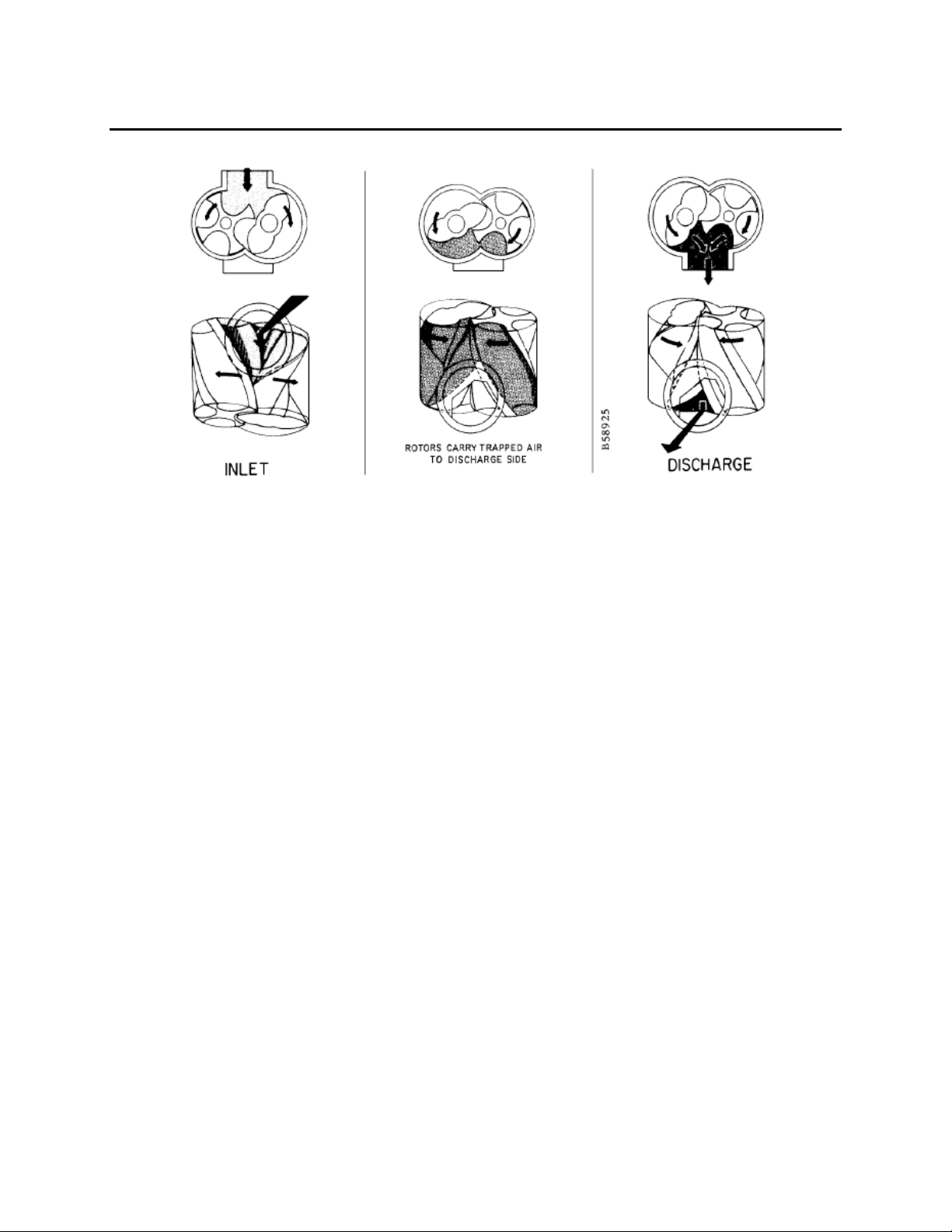
FIGURE 2-1 – OPERATING PRINCIPLE ....................................................................................................................10
FIGURE 2-2 – ACCESSORIES AND SAFETY DEVICES ...........................................................................................11
FIGURE 2-3 – BELT DRIVE OVERHUNG LOAD CALCULATIONS............................................................................14
FIGURE 2-4 – OUTLINE DIMENSIONS .....................................................................................................................18
FIGURE 2-5 – OUTLINE DIMENSIONS .....................................................................................................................18
FIGURE 3-1 – MAXIMUM RATING..............................................................................................................................19
FIGURE 3-2– INLET WATER INJECTION DIAGRAM.................................................................................................20
FIGURE 3-3 – LIQUID RATE.......................................................................................................................................20
FIGURE 3 4 – WATER QUALITY REQUIREMENTS...................................................................................................21
FIGURE 3-5 – ALTITUDE – PRESSURE/VACUUM ....................................................................................................22
FIGURE 3-6 – MINIMUM SPEED, MAXIMUM PRESSURE OR VACUUM .................................................................23
FIGURE 4-1 – AEON PD SYNTHETIC LUBRICANT.................................................................................................. 25
FIGURE 4-2 – SYNTHETIC LUBRICANT CHART.......................................................................................................25
FIGURE 4-3 – NON SYNTHETIC LUBRICANT CHART..............................................................................................27
FIGURE 4-4 – OIL BATH FILTER................................................................................................................................28
FIGURE 4-5 – OIL WETTED FILTER - SILENCER .....................................................................................................28
FIGURE 4-6 – DRY TYPE FILTER AND FILTER-SILENCER .....................................................................................28
FIGURE 6-1 – ADAPTOR PLATE................................................................................................................................37
FIGURE 6-2 – ALTERNATE ADAPTOR PLATES .......................................................................................................37
FIGURE 6-3 – BEARING CARRIER ............................................................................................................................38
FIGURE 6-4 – BEARING CLAMP PLATE....................................................................................................................38
FIGURE 6-5 - PULLER ................................................................................................................................................38
FIGURE 6-6 – ROTOR REMOVAL ..............................................................................................................................39
FIGURE 6-7 – BEARING CARRIER ............................................................................................................................39
FIGURE 7-1 – ROTOR SHAFT SEAL.......................................................................................................................... 41
FIGURE 7-2 – BEARING SPACER..............................................................................................................................41
FIGURE 7-3 – DISCHARGE OPENING.......................................................................................................................41
FIGURE 7-4 – ROTORS ..............................................................................................................................................41
FIGURE 7-5 – ANGULAR CONTACT BEARING ASSEMBLY ....................................................................................42
FIGURE 7-6 – BEARING INSTALLATION...................................................................................................................42
FIGURE 7-7 – DISCHARGE END BEARING CARRIER .............................................................................................42
FIGURE 7-8 – ROTOR END CLEARNACE CHART (UNIT COLD) .............................................................................43
FIGURE 7-9 – DEPTH MICROMETER........................................................................................................................43
FIGURE 7-10 – OUTSIDE MICROMETER ..................................................................................................................43
FIGURE 7-11 – DISCHARGE OPENING.....................................................................................................................44
FIGURE 7-12 – DIAL INDICATOR...............................................................................................................................44
FIGURE 7-13 – SEAL INSTALLATION GUIDE............................................................................................................45
FIGURE 7-14 – SEAL INSTALLATION GUIDE............................................................................................................45
FIGURE 7-15 – BEARING SHIMS ...............................................................................................................................46
FIGURE 7-16 – BEARING SHIMS ...............................................................................................................................46
FIGURE 7-17 – BEARING PRESS PLATE..................................................................................................................47
FIGURE 7-18 – BEARING CLAMP PLATES ...............................................................................................................47
FIGURE 7-19 – DISCHARGE END CLEARANCE CHECK .........................................................................................47
FIGURE 7-20 – OIL SLINGER.....................................................................................................................................47
FIGURE 7-21 – END COVER ASSEMBLY..................................................................................................................48
FIGURE 7-22 – BEARING BORE ................................................................................................................................48
FIGURE 7-23 – DEPTH MICROMETER......................................................................................................................48
FIGURE 7-24 – OIL SEAL ON GATE ROTOR SHAFT ASSEMBLY............................................................................49
FIGURE 7-25 – SLIDE SHIMS OVER SHAFT ASSEMBLY.........................................................................................50
FIGURE 7-26 – PRESS PLATE & JACK SCREW ASSEMBLY...................................................................................50
FIGURE 7-27 – INTALL HUB & PINION PULL TIGHT ................................................................................................50
FIGURE 7-28 – SMALLEST MINUS READING ...........................................................................................................51
FIGURE 7-29 – SMALLEST PLUS READING .............................................................................................................51
FIGURE 7-30 – SETTING THE INTERLOBE CLEARANCE........................................................................................52
FIGURE 7-31 – HOLD GEAR & SHAFT FROM TURNING TIGHTEN FIVE GEAR TO HUB ......................................52
FIGURE 7-32 – FASTENER TORQUE VALUES .........................................................................................................52
FIGURE 7-33 – FASTENERS & LOCKNUT – TORQUE VALUES CHART .................................................................53

37-1-614 Page 8
SAFETY PRECAUTIONS
Safety is everybody’s business and is based on your use of good common sense. All situations or circumstances
cannot always be predicted and covered by established rules. Therefore, use your past experience, watch out for
safety hazards and be cautious. Some general safety precautions are given below:
Failure to observe these notices could result in injury to or death of personnel.
•Keep fingers and clothing away from blower inlet and discharge ports,
revolving belts, sheaves, drive coupling, etc.
•Do not use the air discharge from this unit for breathing – not suitable for human
consumption.
•Do not loosen or remove the oil filler plug, drain plugs, covers or break any
connections, etc., in the blower air or oil system until the unit is shut down and
the air pressure has been relieved.
•Electrical shock can and may be fatal.
•Blower unit must be grounded in accordance with the National Electrical Code. A
ground jumper equal to the size of the equipment ground conductor must be used to
connect the blower motor base to the unit base.
•Open main disconnect switch, tag and lockout before working on the control.
•Disconnect the blower from its power source, tag and lockout before working on the
unit – this machine is automatically controlled and may start at any time.
Failure to observe these notices could result in damage to equipment.
•Stop the unit if any repairs or adjustments on or around the blower are required.
•Disconnect the blower from its power source, tag and lockout before working on the
unit – this machine is automatically controlled and may start at any time.
•Do not exceed the rated maximum speed value shown on the nameplate.
•Do not operate unit if safety devices are not operating properly. Check periodically.
Never bypass safety devices.

37-1-614 Page 9
INTRODUCTION
YOUR KEY TO TROUBLE FREE SERVICE
Although Gardner Denver blowers are sturdy, precision-engineered machines, there are several relatively
simple but basic installation and maintenance procedures that must be observed to assure optimum
performance. As there is no guesswork in the manufacture of these highly advanced units, there must be
none in preparing them to get the job done in the field.
It is the purpose of this manual to help you properly install, maintain and service your Gardner Denver
blower. It is important that no section be overlooked when preparing to install your blower.
Follow the instructions carefully and you will be rewarded with years of trouble-free operation.
SECTION 1
EQUIPMENT CHECK
Before uncrating, check the packing slip carefully to be sure all the parts have been received. All
accessories are listed as separate items on the packing slip, and small important accessories such as
relief valves can be overlooked or lost. After every item on the packing slip has been checked off,
uncrate carefully. Register a claim with the carrier for lost or damaged equipment.
Customers are cautioned to provide adequate protection, warning and safety equipment
necessary to protect personnel against hazards involved in installation and operation of this
equipment in the system or facility.
STORAGE
Your Gardner Denver Blower was packaged at the factory with adequate protection to permit normal
storage for up to six (6) months.
If the unit is to be stored under adverse conditions or for extended periods of time, the following additional
measures should be taken to prevent damage.
1. Store the blower in a clean, dry, heated (if possible) area.
2. Make certain inlet and discharge air ports are tightly covered to prevent foreign material from
entering the air box.
3. All exposed, non-painted surfaces should be protected against rust and corrosion.
4. Provide adequate protection to avoid accidental mechanical damage.
5. In high humidity or corrosive environments, additional measures may be required to prevent
rusting of the blower internal surfaces.
6. To prevent rusting of gears, bearings, etc., the oil reservoirs may be filled with normal
operating oil.
Before running the blower, drain the oil and replace to the proper operating level with clean,
fresh lubricant.
7. Rotate the blower shaft (10 to 25 turns) monthly during storage. Inspect the blower shaft
(near the shaft seal area) monthly and spray with rust inhibitor if needed.
8. For long term storage (over six (6) months), contact Gardner Denver Customer Service for
recommendations.

37-1-614 Page 10
SECTION 2
INSTALLATION
FIGURE 2-1 – OPERATING PRINCIPLE
GENERAL – The CycloBlower® is a compact, rotary lobe type axial flow blower. The meshing of two
screw type rotors synchronized by timing gears provides controlled compression of the air for maximum
efficiency and pulsation free discharge.
OPERATING PRINCIPLE – Compression is effected by the main
(2 lobe) and gate (4 flute) rotors meshing enclosed in the housing. The timing gears maintain close rotor
clearances. The rotors do not touch each other, the housing, or the bearing carriers. Although
clearances are small, lubrication in the compression chamber is not required, insuring oil-free air delivery.
The compression cycle (FIGURE 2-1) begins as the rotors unmesh at the inlet port. Air is drawing into
the rotor cavities, trapped, and compressed by the reducing cavities as rotation continues. When proper
compression is made, the cavities cross the discharge port, completing the cycle. The cycle occurs twice
each revolution of the main bearing rotor and is continuous.
CONSTRUCTION – All models of the 7CDL Series CycloBlower®are of similar design and construction
except for rotor length. The housing is a one-piece casting with flanged inlet and discharge openings.
The rotors are ductile iron with integral cast shaft. Rotors are dynamically balanced for vibration-free
operation. Helical timing gears are of alloy steel, hobbed and shaved for quiet operation.
Two heavy-duty angular-contact ball bearings are used on each rotor shaft, at the discharge end, as fixed
bearings to maintain rotor end clearance.
A radial bearing is used on each rotor shaft at the gear end as a floating bearing.
All gears and bearings are oil splash lubricated.
Standard construction is top inlet, bottom discharge, with drive shaft extension from main rotor at the
discharge end. Rotation is clockwise facing the drive shaft. Blowers may be mounted for either V-belt or
direct-coupled drive. The gate rotor speed is half (1/2) the main rotor or drive speed.

37-1-614 Page 11
FIGURE 2-2 – ACCESSORIES AND SAFETY DEVICES
LOCATION – Select a clean, dry, well-ventilated area for installing blower and allow ample room for
normal maintenance. Proper ventilation is necessary for blower cooing and cool air intake.
Do not electric weld on the blower or base; bearings can be damaged by the passage of current.
FOUNDATIONS – Correct supporting is important. Distortion by incorrect supporting will affect internal
operating clearances. The foundation or base must provide a level, rigid, nonworking support for the
blower. It must be on uniform and solid footing. Complete foundation design cannot be given because of
varying conditions. If necessary, use shims under feet for leveling to prevent distortion when foundation
bolts are tightened. After installation on the foundation is complete, check alignment of the coupling or
drive before starting blower.
ACCESSORIES (FIGURE 2-2) – The type of service determines the accessory group required. The
typical items are listed as follows:
1. Inlet Filter or Filter-silencer.
2. Flexible Coupling
3. Driver.
4. Simple V-Belt Drive.
5. Jackshaft V-Belt Drive.
6. Bypass Valve.
7. Check Valve.
8. Relief Valve, Vacuum or Pressure.
9. Discharge Silencer.
10. Base Plate.
11. Expansion Joint(s) – Inlet and/or Discharge.
12. Temperature or Pressure Shutdown Switch.
13. Check Valve (Inlet Bypass).
14. Heat Exchanger.
15. Bypass to atmosphere (alternate).
16. Pressure Gauge or Vacuum Gauge.

37-1-614 Page 12
Inlet Filter or Filter-Silencer – For pressure service handling air, the blower inlet must be protected by a
filter of suitable size to allow full flow of air to the blower inlet. The filter must be of adequate efficiency to
trap any foreign materials which may be in the general area of the air inlet. If noise is a factor, filter-
silencers are available.
Rotating components will cause severe injury in case of personal contact. Keep hands away
from the blower inlet and discharge ports.
In choosing a location for the filter, consideration should be given to a source of cool, clean air, and most
important, access for maintenance.
Filters generally used for blower service fall under three types:
Oil-wetted Screen Type
Oil Bath
Dry Type
Filter-silencers are also available in the above types.
For vacuum service, the type of system used and materials being handled will determine the necessity for
an in-line filter.
Couplings – For direct-coupled units, a flexible type coupling, accurately aligned, should be used
between the blower and power unit. A grid type coupling is recommended. Misaligned couplings may
cause vibration, additional bearing loads and stresses which will affect life of parts involved. DO NOT
drive the couplings on shaft. Check shaft and coupling bore for burrs. Polish the shaft and bore if
necessary for proper fit. Fit keys to keyways. Check coupling alignment. Exact alignment will vary with
the type of couplings; however, it is not uncommon to hold alignment within .003” in all directions. With
lubricated or special couplings, follow the manufacturer’s instructions for installation and maintenance.
Do not use couplings that may cause an axial thrust during operation.
DRIVE INSTALLATION
V-Belt Drive – Follow normal specifications recommended by the belt manufacturers for installation of
belt drive on blowers. To provide the most compact drive, it is suggested that high capacity V-belt drives
be used. Blower shaft and power unit shaft should be parallel, with sheaves aligned on shafts so belts
run true. Use only matched belt sets and replace belts in complete sets only. Belt tension should be
according to manufacturer’s recommendations. Slippage can be detected by belt squeal, overheating or
loss of speed. A few hours after initial starting with new belts, it is advisable to recheck belt tension and
provide tension adjustment as necessary.
Over tightening belts leads to heavy bearing loads and premature failure.
When selecting a V-belt drive, check to be sure the maximum allowable moment limitation is not
exceeded. Refer to (Figure 2-3 page 14), for V-belt drive overhung load calculations. (Figure 2-3),
applies to V-belt calculations only. Exceeding overhung load limitations leads to premature bearing
failure and potential shaft breakage.

37-1-614 Page 13
NOTICE
When a simple V-belt drive is not available, to stay within the maximum allowable moment, a
jackshaft V-belt drive is required.
Belt drives must be carefully aligned. Motor and blower pulleys must be parallel to each other and in the
same plane within 1/16 inch. Belt tension should be carefully adjusted and belts tightened only enough to
prevent slippage.
NOTICE
The sheave should be positioned as close as possible to the drive cover. This will reduce the
overhung load and extend the bearing life.
On direct connected units, alignment and lubrication of the couplings to specifications of the coupling
manufacturer are very important. When mounted drives are supplied from the factory, proper alignment
has been established before shipment. However, during shipping, handling and installation, it is likely
that the alignment has been disturbed and final adjustment must be made before startup.
Synchronous-Belt Drive – Synchronous belts are not recommended for usage on Gardner Denver
positive displacement blowers. Installation of synchronous belts is critical and can result in alignment,
tensioning and vibration problems, which contribute to higher than normal loads and stresses on the
blowers.

37-1-614 Page 14
Dimensions
(Inches)
7CDL
Drive
Shaft
Location A B C
(Max)
Maximum
Allowable
Moment
(LB-IN)
Discharge
End
(Standard)
8.64 3.65 0.5 5,985
Gear
End
(Optional)
10.12 5.30 0.5 5,985
MAXIMUM ALLOWABLE MOMENT
DRIVE SHAFT ILLUSTRATION
Z Ac Z Ac Z Ac Z Ac Z Ac Z Ac
0.000 1.000 0.250 0.966 0.500 0.926 0.750 0.879 1.000 0.823 1.250 0.751
0.025 0.997 0.275 0.962 0.525 0.922 0.775 0.874 1.025 0.816 1.275 0.742
0.050 0.994 0.300 0.958 0.550 0.917 0.800 0.869 1.050 0.810 1.300 0.734
0.075 0.990 0.325 0.954 0.575 0.913 0.825 0.864 1.075 0.803 1.325 0.725
0.100 0.987 0.350 0.951 0.600 0.908 0.850 0.858 1.100 0.796 1.350 0.716
0.125 0.983 0.375 0.947 0.625 0.904 0.875 0.852 1.125 0.789 1.375 0.706
0.150 0.980 0.400 0.943 0.650 0.899 0.900 0.847 1.150 0.782 1.400 0.697
0.175 0.977 0.425 0.939 0.675 0.894 0.925 0.841 1.175 0.774 1.425 0.687
0.200 0.973 0.450 0.935 0.700 0.889 0.950 0.835 1.200 0.767
0.225 0.969 0.475 0.930 0.725 0.884 0.975 0.829 1.225 0.759
ARC OF CONTACT FACTORS
Belt Pull = 2.5 – Ac 125954 x Hp x S.F.
Ac D x RPM
Key: Ac = Arc of Contact Factor (Refer to Arc of Contact Factor Chart above)
Hp = Blower Horsepower for Operating Conditions
S.F. = Drive Servce Factor (use 1.4 S.F. for continuous duty applications)
D = Blower Sheave Pitch Diameter in Inches
RPM = Blower Sheave Speed
Z = Large Sheave Pitch Diameter (in) – Small Sheave Pitch Diameter (in)
Sheave Center Distance (in)
CALCULATION OF BELT PULL
Shaft Moment (LB-IN) = Belt Pull x B + C + Sheave Width
2
CALCULATION OF SHAFT MOMENT
FIGURE 2-3 – V-BELT DRIVE OVERHUNG LOAD CALCULATIONS

37-1-614 Page 15
Bypass Valve – Installation of a bypass valve at the blower discharge (FIGURE 2-2, page 11) will allow
the blower to be started under no-load. Bypass line may be discharged at atmosphere or to blower inlet
depending on local requirements or material being handled.
Heat Exchanger – When the bypass line discharges to blower inlet, a heat exchanger must be included
in the line between blower discharge and blower inlet, to remove the heat of compression before the gas
is reintroduced into the blower inlet. A check valve (FIGURE 2-2, page 11) should also be placed in the
inlet line between the bypass line and the inlet filter or silencer, to prevent discharging backwards through
the filter or silencer.
SAFETY DEVICES – For all installations the following safety devices are a requirement for safe blower
operation. Numbers shown are reference numbers used in (FIGURE 2-2, page 11).
7. Check Valve, Blower Discharge Line
8. Relief Valve, Vacuum or Pressure
12. High Discharge Air Temperature Switch
Check Valve (FIGURE 2-2, page11) – When the blower is used in a pneumatic conveying system, a check
valve must be used to prevent backflow of material into the blower. In any system it is a safety device
preventing the down stream pressure from motoring the blower through shutdown periods. A check valve
must be provided for each blower when several blowers are manifold into a common system.
Relief Valve (FIGURE 2-2, page11) –The relief valve must be installed as close to blower ports as
possible. There should be no accessories such as valves, check valves, silencers, etc. between the relief
valve and blower ports. It should be set 2 to 3 PSI above blower operating pressure (1/2” to 1” Hg. In
vacuum service).
NOTICE
Relief valves should be placed as close as possible to the blower inlet port (vacuum operation)
or discharge port (pressure operation).
High Temperature and High Pressure Shutdown – All blower installations should be protected with a
high temperature shutdown switch. The controls should be set to stop the blower when the discharge
temperature reaches 355° F. In some installations a high pressure shutdown switch may also be
advisable. The sensing element of these controls should be installed as close to the blower discharge as
possible. See (FIGURE 2-2, page 11). On remote or unattended installations these controls are normally
mandatory.
INLET PIPING – During the installation of piping make sure dirt and other foreign materials do not enter
blower openings. When inlet piping is used IT MUST BE CLEAN, AND FREE OF SCALE AND OTHER
FOREIGN MATERIALS WHICH COULD ENTER THE BLOWER. It is suggested that an expansion joint
be installed near blower openings to prevent stressing of the blower housing. Support the pipe to relieve
weight on the expansion joint and the blower. Make sure the pipe size is adequate and as straight as
possible to prevent pressure drop at the blower inlet. Where bends are necessary use long radius
fittings. All connections must be air tight.
For vacuum service, an accurate vacuum gauge must be used near the blower inlet to indicate operating
vacuum and a suitable vacuum relief valve must be used. A vacuum blower in pneumatic conveying
service requires pre-inlet separation and filtering to prevent material carry-over into the blower.
Estimated Inlet pipe size is determined as follows:
0 to 10 feet long, use pipe size equal to blower inlet flange size.
10 to 17 feet long, use pipe size larger than blower inlet.
17 to 33 feet long, two pipe sizes larger than blower inlet.

37-1-614 Page 16
DISCHARGE PIPING – In general, the type of system used will govern the piping arrangement.
However, the following suggestions should be followed for blower protection and efficiency.
An expansion joint should be installed as close to the blower opening as possible to protect the blower
housing from stresses. All pipe connections should be square and even to prevent distortion from
misalignment.
An accurate pressure gauge must be provided near the blower discharge to indicate operation pressure.
If noise level is a factor, a discharge silencer should be used. The discharge line should be as straight as
possible. Where bends are necessary, use long radius fittings. Provision for condensate drainage at the
lowest point in the piping may be required.
VENTILATION – If the blower is to operate in a housing or enclosure, proper ventilation must be provided
for adequate blower cooling. Cooling air should be taken from outside the enclosure.

37-1-614 Page 17
FIGURE 2-4 – OUTLINE DIMENSIONS
TOP INLET, MAIN ROTOR DRIVE

37-1-614 Page 18
TOP INLET, MAIN ROTOR DRIVE
MODEL WT.
(lbs.)
A
(Inches)
B
(Inches)
C
(Inches)
D
(Inches)
OUTLINE
DIMENSIONS
DRAWING NO.
7CDL11P 880 34.50 1.5 20.38 28.25 302CBL800
7CDL14P 940 37.50 4.5 23.38 31.25 303CBL800
7CDL17P 1033 40.50 7.5 26.38 34.25 301CBL800
FIGURE 2-5 – OUTLINE DIMENSIONS (CONTINUED)

37-1-614 Page 19
SECTION 3
OPERATION
Future operating problems can be avoided if proper precautions are observed when the equipment is first
put into service.
Before starting under power, the blower should be turned over by hand to make certain there is no
binding or internal contact.
Each size blower has limits on pressure differential, running speed, and discharge temperature which
must not be exceeded. These limits are shown in the following tables and text in section 3.
GENERAL – A new blower from the factory must be checked and serviced before operation. The blower
must be lubricated and operated according to the following instructions. Blower failure can be caused by
operation at above rated pressure or below rated minimum speed. Both cause excessive discharge
temperature and seizure of rotating parts.
STARTING BLOWER – Start at reduced speed and no-load if possible. If speed is fixed, start without
load by bleeding discharge to atmosphere. Starting should be smooth and free of vibrations. After initial
no-load start, and operation is satisfactory, apply load gradually until maximum operating conditions are
attained. BE SURE OPERATING CONDITIONS ARE WITHIN BLOWER RATINGS. Maintain a close
check for severe vibrations, unusual noise, leaks and undue heating. The blower will gradually heat up
due to compression, but after a reasonable length of time, temperature will stabilize. With very cold
ambient conditions, warm up blower at no-load before going into full load service.
If the blower is used as part of a specific system, check the system’s manual for any procedures that may
be necessary when starting the blower.
PRESTART CHECK (For New or Overhauled Blower) – see “Blower Startup Checklist,” page 24.
ROTATION – Facing the main rotor drive shaft, rotation is clockwise when the shaft extension is at
discharge end, and counterclockwise when the shaft extension is at the inlet end. An arrow indicating
rotation is attached to the blower end cover near the drive shaft.
DAILY CHECK
1. Air filter tight, clean and serviced.
2. Proper oil level in oil sumps.
3. Observe pressure.
4. Relief valve functions.
5. Blower turns freely.
Operating beyond the specified operating limitations will result in damage to the unit.
P
Series
Models
Drive Shaft
Speed
(RPM)
Discharge
Pressure*
Sea Level (PSIG)
Dry
Vacuum*
(Inches Hg)
Wet
Vacuum*
(Inches Hg)
7CDL11, 7CDL14, 7CDL17 4000 20 17 ----
7CDL11, 7CDL14, 7CDL17 3600 ---- ---- 24
* Pressures or vacuums are gauged at immediate blower discharge or inlet. For suggested
maximum ratings at reduced speeds, See (FIGURE 3-6, page 23).
FIGURE 3-1 – MAXIMUM RATING

37-1-614 Page 20
FIGURE 3-2– INLET WATER INJECTION DIAGRAM
TYPE OF SERVICE – The blower can be operated in either pressure or vacuum service.
Pressure – Never operate the blower above the maximum pressure shown in
FIGURE 3-1, page 19. Excessive pressure may cause overheating and blower failure, it is therefore most
important to have an accurate pressure gauge in the discharge line as close to the blower discharge as
possible. Reduced speeds have a direct affect on allowable pressure (FIGURE 3-6 page 23 ). A bypass
valve to bleed air from the discharge to atmosphere (FIGURE 2-2, page 11) may be used to control the
pressure. NEVER reduce the blower speed to maintain a certain pressure before it is determined if the
reduced speed is adequate for that pressure. An accurate pressure gauge must be maintained.
7CDL11 7CDL14 7CDL17
Liquid Rate
(GPM) 2 2 2
FIGURE 3-3 – LIQUID RATE
Vacuum – The blower may be operated either in dry vacuum or wet vacuum service. Do not operate the
blower above the maximum vacuums shown in
FIGURE 3-1, page 19, or below the minimum speed shown in FIGURE 3-6, page 19. All vacuum ratings
are based on standard atmospheric discharge. An accurate vacuum gauge and vacuum relief valve must
be used as close to the blower inlet as possible.
Wet vacuum service employs a suitable liquid, normally water, injected into the system near the blower
inlet to control temperature rise and increase the degree of vacuum developed. The liquid used MUST
BE clean and free of foreign matter, chemical contaminants and hardness, which may cause corrosion,
deposits, or damage in the rotor chamber. See FIGURE 3-2, for typical installation, and FIGURE 3-4,
page 21 for water quality requirements. If the proposed water supply is questionable, or does not meet
the water specification, a reputable water treatment service company should be contacted. They can
recommend treatment and equipment to satisfy this specification.
This manual suits for next models
1
Table of contents
Other GD Water Pump manuals
Popular Water Pump manuals by other brands

Pentair
Pentair Myers AWS-1 Installation and service manual

SFA
SFA Sanibest 128 installation instructions

Sumak
Sumak SMH120 user guide

BUSCH
BUSCH Mink MB 0018 A instruction manual

ETATRON D.S.
ETATRON D.S. eOne MA Operating instructions and maintenance

PEERLESS
PEERLESS PVF Series Installation and operating instructions