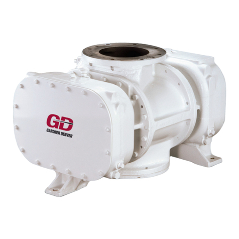
GD AQUALINE 1100 Manual

AQUALINE
1100/1600/2100/2700
Installation
Operating &
Maintenance
Instructions
4990671000
February 2008

Contents
4990671000 February 2008 2
Contents
Contents
1. Technical data . . . . . . . . . . . . . . . . . . . . . 5
1.1 Machine data . . . . . . . . . . . . . . . . . . . . . . . . .5
1.2 Dimensions . . . . . . . . . . . . . . . . . . . . . . . . . .6
1.2.1 Connection versions. . . . . . . . . . . . . . . . . . . .7
1.3 Location of lubricating points . . . . . . . . . . . . .8
1.4 Operating fluid . . . . . . . . . . . . . . . . . . . . . . . . 8
1.5 Drive. . . . . . . . . . . . . . . . . . . . . . . . . . . . . . . .8
2. Safety instructions and hazard alerts . . 9
2.1 Use for intended purpose. . . . . . . . . . . . . . . .9
2.2 Acceptance and monitoring . . . . . . . . . . . . . .9
2.3 Hazard alerts and symbols. . . . . . . . . . . . . . .9
2.4 Safe working . . . . . . . . . . . . . . . . . . . . . . . . .9
3. Transport, Storage and Scope of
delivery . . . . . . . . . . . . . . . . . . . . . . . . . . 11
3.1 Transport . . . . . . . . . . . . . . . . . . . . . . . . . . .11
3.2 Storage. . . . . . . . . . . . . . . . . . . . . . . . . . . . .11
3.3 Scope of delivery . . . . . . . . . . . . . . . . . . . . .11
4. Installation . . . . . . . . . . . . . . . . . . . . . . . 12
4.1 System setup with cooler in main flow . . . . .12
4.2 System setup with cooler in side flow . . . . .13
4.3 Point of installation and fastening . . . . . . . .15
4.4 Connections and piping . . . . . . . . . . . . . . . .15
4.5 Protection against intake of dirt and
residue . . . . . . . . . . . . . . . . . . . . . . . . . . . .16
4.5.1 Suction line. . . . . . . . . . . . . . . . . . . . . . . . . .16
4.5.2 Vacuum filter . . . . . . . . . . . . . . . . . . . . . . . .16
4.5.3 Safety dome . . . . . . . . . . . . . . . . . . . . . . . . . 16
4.5.4 Safety bowl. . . . . . . . . . . . . . . . . . . . . . . . . .16
4.6 Safety and monitoring instruments. . . . . . . .16
4.6.1 Vacuum gauge . . . . . . . . . . . . . . . . . . . . . . . 17
4.6.2 Vacuum filter . . . . . . . . . . . . . . . . . . . . . . . .17
4.6.3 Non-return valve. . . . . . . . . . . . . . . . . . . . . .17
4.6.4 Thermometer . . . . . . . . . . . . . . . . . . . . . . . .17
4.6.5 Safety valve . . . . . . . . . . . . . . . . . . . . . . . . .17
4.6.6 Pressure gauge . . . . . . . . . . . . . . . . . . . . . .17
4.6.7 Guard . . . . . . . . . . . . . . . . . . . . . . . . . . . . . . 18
4.6.8 Bellows. . . . . . . . . . . . . . . . . . . . . . . . . . . . .18
4.6.9 Speed monitor . . . . . . . . . . . . . . . . . . . . . . .18
4.7 Operating fluid . . . . . . . . . . . . . . . . . . . . . . . 18
4.7.1 Operating water back-cooling and
storage tank . . . . . . . . . . . . . . . . . . . . . . . . .18
4.7.2 Cell Ventilation . . . . . . . . . . . . . . . . . . . . . . .19
4.8 Drive. . . . . . . . . . . . . . . . . . . . . . . . . . . . . . .19
4.8.1 Drive by hydraulic motor . . . . . . . . . . . . . . .19
4.8.2 Drive by flexible clutch . . . . . . . . . . . . . . . . .19
4.8.3 Drive by propeller shaft . . . . . . . . . . . . . . . .19
4.9 Drive by Vee belt . . . . . . . . . . . . . . . . . . . . . 20
5. Start-up . . . . . . . . . . . . . . . . . . . . . . . . . . 22
5.1 Testing the system . . . . . . . . . . . . . . . . . . . .22
5.2 Operating liquid . . . . . . . . . . . . . . . . . . . . . .22
5.3 Stop slide and shut-off valves . . . . . . . . . . .22
5.4 Direction of rotation . . . . . . . . . . . . . . . . . . .22
5.5 Drive. . . . . . . . . . . . . . . . . . . . . . . . . . . . . . .22
5.6 Inspection of speed, vacuum and pressure .22
5.6.1 Speed. . . . . . . . . . . . . . . . . . . . . . . . . . . . . .22
5.6.2 Vacuum and vacuum gauge . . . . . . . . . . . .22
5.6.3 Pressure at pressure gauge. . . . . . . . . . . . .22
6. Operation . . . . . . . . . . . . . . . . . . . . . . . . 23
6.1 Start-up . . . . . . . . . . . . . . . . . . . . . . . . . . . .23
6.2 Regular inspections . . . . . . . . . . . . . . . . . . .23
6.2.1 Safety valve . . . . . . . . . . . . . . . . . . . . . . . . .23
6.2.2 Water stop valve . . . . . . . . . . . . . . . . . . . . .23
6.2.3 Inspection intervals . . . . . . . . . . . . . . . . . . .24
6.3 Operating the liquid ring pump . . . . . . . . . . . 24
6.3.1 Operating water consumption and control . .24
6.4 Possible faults by the operator . . . . . . . . . . .25
6.5 Extended period of non-use . . . . . . . . . . . .25
6.6 Troubleshooting . . . . . . . . . . . . . . . . . . . . . .26
7. Maintenance . . . . . . . . . . . . . . . . . . . . . 28
7.1 Warranty. . . . . . . . . . . . . . . . . . . . . . . . . . . .28
7.2 Maintenance, maintenance
schedule . . . . . . . . . . . . . . . . . . . . . . . . . . . .28
7.2.1 Water back-cooling with air . . . . . . . . . . . . .28
7.2.2 Liquid ring pump . . . . . . . . . . . . . . . . . . . . . .28
7.2.3 Vacuum filter (GDD types) . . . . . . . . . . . . . .28
7.2.4 Vee belts and Vee belt tension. . . . . . . . . . .29
7.2.5 Non-return valve . . . . . . . . . . . . . . . . . . . . . .29
7.3 Lubrication . . . . . . . . . . . . . . . . . . . . . . . . . .29
7.3.1 Antifriction bearings . . . . . . . . . . . . . . . . . . .29
7.3.2 Shaft seal . . . . . . . . . . . . . . . . . . . . . . . . . . .30
8. Spare parts . . . . . . . . . . . . . . . . . . . . . . 31
8.1 Spare parts. . . . . . . . . . . . . . . . . . . . . . . . . .31
9.

Preface
4990671000 February 2008 3
Preface
Dear customer,
Your new Water Ring Pump is the outcome of inten-
sive development based on decades of experience as
a supplier of vacuum pumps and compressors to the
suction vehicle market. Advanced manufacturing
methods in combination with highest quality standards
and extensive testing ensure reliability, a high degree
of availability and long life of your machine.
This machine requires proper handling, especially un-
der severe operating conditions. Startup, operation
and maintenance must must therefore be performed
only by trained and authorised personnel.
These Operating Instructions contain all required infor-
mation and have been written for those in charge of the
unit. The machine will give smooth service over a long
period provided these Instructions are followed. The
Operating Instructions are a component part of the
product and must be kept available for the operating
personnel. You will appreciate that we cannot be held
responsible for any damage caused due to non-com-
pliance with these Instructions.
Please note that repairs should only be undertaken by
authorized repair centres using original parts. Other-
wise our guarantee will be void.
We wish you success with your water ring pump from
Gardner Denver Drum. If you have any questions
which are not answered in this manual, please call us.
Sincerely yours,
Gardner Denver Drum Ltd.

Mode of operation, Design versions
4990671000 February 2008 4
Mode of operation, Design versions
Mode of operation
Liquid compressor vacuum pumps, like rotary com-
pressor vacuum pumps, work on the displacement
principle, providing uniform, low-pulsation flow.
Single-shaft liquid ring machines have a housing with
cylindrical bore and an eccentrically mounted rotor.
The housing is partly filled with liquid, which the rota-
tion of the rotor forms into a rotating liquid ring in con-
tact with the housing. Together with the hub of the
eccentrically mounted rotor, it forms a sickle-shape
working space divided by the vanes of the rotor.
The rotation of the rotor causes the cell volume to be-
come large at the intake side. This creates a vacuum
which sucks air into the cell, which is open towards the
air intake. As the rotation continues, the cell closes and
the cell volume becomes smaller. As a result of this,
the enclosed air is compressed and pushed out of the
pressure outlet.
The cells are charged and drained through openings in
the housing covers located on either side of the rotor
faces.
This functional principle causes the machine to work at
nearly isothermal compression due to internal cooling.
The first digit of the references to illustrations
in these Operating Instructions refers to the
chapter in which you find the illustration. The
illustrations within each chapter are numbered
consecutively. The last number of an illustra-
tion reference denotes the position number of
the item in the references illustration.
For example, the reference (7.2 / 3):
second illustration in chapter 7, item number 3.
This symbol precedes information that refers
to units used in a potentially explosive atmos-
phere.
Design versions
The design versions differ in their direction of rotation.
Type code:
AQUALINE 2100 R
Liquid ring pump,
operating
medium: water1)
1) Water is the working liquid commonly used by suction vehicles.
Machine size R = CW rotation
L = CCW rotation

Technical data
4990671000 February 2008 5
Technical data
1. Technical data
1.1 Machine data
Liquid ring pumps of the Aqualine series use water as
operating fluid.
Conveyed medium
Air of maximum intake temperature of 60 °C.
Operating fluid
Water or water-glycol mixture
Maximum outlet temperature
The temperature at the outlet of the liquid compressor
vacuum pump should be restricted to maximum 65 °C.
The machine number and other important machine
data are given on the machine’s nameplate.
Liquid ring pump Aqualine
1100
Aqualine
1600
Aqualine
2100
Aqualine
2700
Rated operating vacuum (absolute) mbar 400 400 400 400
Maximum gauge pressure in
compressor operation1) barg 1.5 1.5 1.5 0.5
At 400 mbar (absolute) intake pressure
volume flow rate
final gauge pressure
power consumption on shaft
m3/h
barg
kW
900
0.0
32
1,300
0.0
46
1,700
0.0
60.5
2,075
0.0
74
At 1,000 mbar (absolute) intake pressure
volume flow rate
final gauge pressure
power consumption on shaft
m3/h
barg
kW
840
0.5
33
1,270
0.5
50
1,660
0.5
65
2,100
0.5
84
Possible max. intermitant vacuum (absolute)
approx.2) mbar 130 130 130 130
Rated speed3) 1/min 1,500 1,500 1,500 1,500
Mass moment of inertia, incl. liquid ring kgm20.7 1.0 1.3 1.6
Sound pressure at 7 m distance at 400 mbar
(absolute) dB(A)66687072
Weight of the basic machine kg 150 165 180 195
All data relate to water at 20°C inlet temperature as the operating fluid and intake temperature of 20°C.
Operating fluids other than water or water-glycol mixture require prior consultation with the manufacturer.
The data and illustrations reflect the current state. The right of modifications is reserved.
1) Secure by providing a safety valve.
2) Dependant on water temperature.
3) The permitted speed range from 1,100 to 1,500 rpm must be observed.

Technical data
4990671000 February 2008 6
1.2 Dimensions
Fig. 1.1 Dimensions of Aqualine 1100 to 2700
E
F
G
H
Air
Water
b
590
448
Ø 48
k6
80
270
a
c
M16
26
AB
45°
479
370
157
210
18
200
274
50 122
190
500
52
147,5
C
D
a b c Machine serial no. Connection
for
additional
ventilation
Z1) 2) 3)
1) One-side cell venting Z only for connection to the machine numbers in this table.
2) Second venting lines on opposite side required for machine serial nos. 910 390/.., 910 400/.. et 910 410/.. for housing pipe socket
Z = G 11⁄4" and OD = 28 mm.
3) If conditions at the installation site require a second cell venting line, the minimum diameter in the table above also applies.
Ø Cell
venting
line I/D
Connection
for liquid
ring fluid
Ø
Operating
water line
Weight
[mm] [mm] [mm] cw
rotation
ccw
rotation [mm] [kg]
Aqualine
1100 170 355 630 910 389/.. 910 381/..
Optional
G 1"
or
G 11⁄2"
28
G 11⁄2"R1
1⁄2"
150
Aqualine
1600 260 400 720 910 399/.. 910 382/.. 165
Aqualine
2100 350 445 810 910 409/.. 910 383/.. 180
Aqualine
2700 450 495 910 910 439/.. 910 440/.. G 11⁄2" 52 195
A
A-Side
BB-Side
C Connecting flanges with connecting variations (see figure 1.2)
D Drain for the liquid ring fluid G 3/4"
E Connection for an additional ventilation Z
F Drain for an additional ventilation G 3/4"
G Connection for the liquid ring fluid G 11/2";
Operating water inflow duct – drain
H Covered on A-side and B-Side

Technical data
4990671000 February 2008 7
1.2.1 Connection versions
Fig. 1.2 Connection sizes for Aqualine 1100 to 2700 versions (in mm)
Version I Version II Version III Version IV Version V Version VI
DEDEDEDEDEDE
Aqualine 1100 335 670 263 526 373 746 263 526 297 594 297 594
Aqualine 1600 380 760 308 616 418 836 308 616 342 684 342 684
Aqualine 2100 425 850 353 706 463 926 353 706 387 774 387 774
Aqualine 2700 475 950 403 806 513 1026 403 806 437 874 437 874
Version I
E
D
506
Part number
910 423 00
Version II
E
D
E
D
E
D
E
D
E
D
577
504
616 504
540238
28
Part number
910 423 00
Version II
8 x Ø14
Flange in acc. with
DIN 28 459 – DN125
Flange in acc. with
DIN 28 459 – DN125
Version I
Version III
Version IV
Version IVVersion III
Version V
Version VI
Version VIVersion V
Ø204
Ø204
Ø176
Ø176
Ø125
Ø125
105
105
105
105
Part number
910 424 00
Part number
910 427 00
Part number
910 427 00
Part number
910 424 00

Technical data
4990671000 February 2008 8
1.3 Location of lubricating points
1.4 Operating fluid
The operating fluid is water or water-glycol mixture.
Operating fluids other than water or water-glycol mix-
ture require prior consultation with the manufacturer.
1.5 Drive
From the vehicle engine:
• by auxiliary drive and propeller shaft
• by Vee belt, whereby the Vee belt pulley is installed
on the free shaft end
• by hydraulic drive
From other engine, electric or hydraulic motor:
•by flexible coupling
• by Vee belt, whereby the Vee belt pulley is installed
on the free shaft end
•For more details, see Installation section.
Fig. 1.3 Lubrication fittings and venting valve
X
Air
Water
X 2:1
0
Cover the lubrication fit-
tings and the venting valve
when final painting!

Safety instructions and hazard alerts
4990671000 February 2008 9
Safety instructions and hazard alerts
2. Safety instructions and hazard alerts
2.1 Use for intended purpose
The intended purpose of the liquid ring pump is to con-
vey and compress filtered air. The entrainment of small
amounts of water in the air is possible. Any use other
than or beyond that described above is contrary to the
intended purpose.
Following the operating data and the specified mainte-
nance are also part of the use for the intended pur-
pose.
Liquid ring pumps of the aqualine series
comply with the requirements of directive 94/
9/EC (ATEX) and belong to equipment group
II, catagory 2, temperature class T4 (135°C
maximum surface temperature), zone 1,2
(gas atmosphere).
Changes and repairs must only be made
with the manufacturer’s written permission.
Units of the Aqualine series are designed for
integration in a higher-level machine. The
new risks created by the integration must be
assessed by the manufacturer of the new
machine.
2.2 Acceptance and monitoring
The liquid ring pump as a unit is not subject to any ac-
ceptance or monitoring requirements.
Any special provisions in effect at the site of the liquid
ring pump must be observed by the operator.
2.3 Hazard alerts and symbols
This hazard alert symbol indicates important
safety messages in this booklet. Carefully read
the message that follows and act as required.
Make certain that the safety instructions are
known to all who need to know them!
“CAUTION” indicates provisions and regula-
tions preventing damage to the machine.
Symbol for potentially explosive atmosphere.
Here the symbol draws attention to provisions
or information which must be observed if the
machine is to be used in a potentially explosive
atmosphere.
This symbol indicates information of particular
importance to the operator of the machine.
This symbol indicates that no unauthorized
persons must enter this area.
Risk of burning!
This symbol indicates a hot surface.
This symbol indicates that you must wear ear
protectors.
This alert symbol indicates that environmental
protection requirements must be observed.
2.4 Safe working
The liquid ring pump has been designed and
built to good engineering practice and the
accepted rules of safety. However, hazardous
situations may still arise in using the machine
with the possibility of personal injury or death
of the operator or other persons and damage
of the machine or other objects.
Air is the only conveyed medium.
• Use the liquid ring pump only in good working con-
dition and for the intended purpose. Be alert to
possible hazards. Defects impairing safety must be
repaired without delay.
• Modifications, additions and alterations of the liq-
uid ring pump that are likely to impair its safety are
forbidden unless agreed with the manufacturer.
• The machine must only be used with delivery and
intake lines connected.
• All warnings on the liquid ring pump must be legi-
ble and observed at all times.
• Work on electrical equipment must be carried out
by a trained electrician applying the rules of the
trade.
• All persons carrying out work on the liquid ring
pump must have read these Operating Instruc-
tions, especially the chapter on safety, before start-
ing work. It may be too late to refer to these
Instructions when work has already started!
• Operation and maintenance of the machine must
only be carried out when the machine is not run-
ning.

Safety instructions and hazard alerts
4990671000 February 2008 10
• Secure the drive against starting before beginning
to work on the machine.
• When work is carried out on the system, the latter
must not be under pressure or vacuum.
On the vehicle: Close the stop slide valve. Bleed or
vent the pressure line between the system and the
stop slide valve.
Relieve elevated pressure manually at the safety
valve. Observe the pressure gauge reading.
• Remove the drive guard only when the machine is
not running.
• Remove the safety guard only when the machine
and the pressure line have cooled down.
• Before starting the machine, make certain that all
guards are installed and in place.
Environmental protection requires that all
emerging fluids, e.g., cooling water, cooling oil
or lubricant residue, are collected and dis-
posed of as prescribed.

Transport
4990671000 February 2008 11
Transport
3. Transport
Symbols on the packaging:
Top
Fragile
Keep dry
3.1 Transport
Avoid any use of force and load / unload the packages
with care.
Attach lifting equipment only at the firmly
installed eye bolts (see figure 3.1).
Remove transport safeguards, where provided.
3.2 Storage
Store the machine in a dry and heated room until in-
stallation. Remove the covers on and pressure open-
ings only at the time of actual installation.
3.3 Scope of delivery
The contents of the consignment are described in the
delivery note. Check for short delivery and transit dam-
age without delay. Claims for damage in transit and
short delivery can only be accepted if made in writing
without delay.
Fig. 3.1 Lifting eye bolt

Installation
4990671000 February 2008 12
Installation
4. Installation
Figures 4.1 and 4.2 show a typical Aqualine liquid ring
pump system completely installed. Other arrangement
versions are also possible.
4.1 System setup with cooler in main flow
Fig. 4.1 Components of a system with liquid ring pump – Cooler in main flow
6
min
max
7 1 8 3 4 9 1a 5 19 12 11
10141518182171314155 16
15
20
For details of shaded area see page 14
1 +1a Vent line
2 Vacuum filter
3 Liquid ring pump
4 Non-return valve
5Bellows
6 Safety valve
7 Pressure gauge
8 Thermometer
9 Operating water tank
10 Four-way directional control
valve
11 Safety dome and float valve
12 Vehicle tank
13 Operating water cooler
14 Water stop valve
15 Drain valves
16 Safety bowl with float valve
17 Flexible mounting
18 Vacuum gauge
19 Float switch
20 Water inlet for filling system
*For dimensions of the vent line, see table page 6

Installation
4990671000 February 2008 13
4.2 System setup with cooler in side flow
Notes
• Installation and start-up must only be undertaken
by trained persons. Damage due to improper han-
dling is not included in the guarantee terms.
• The machine is delivered in fully assembled condi-
tion. It must not have suffered damage in transit.
• Please make certain that the rotor shaft can be
rotated by hand. If this is not the case, inform our
service staff.
• Lift the machine using only the securely installed
eye bolts.
For use in a potentially explosive atmos-
phere,all parts of the equipment must satisfy
the requirements for the zone in which they
are used.
Note that it may be necessary to provide
equipotential bonding between the equip-
ment and the truck. The safe operation of the
vacuum pump in a potentially explosive at-
mosphere requires that all safety instructions
in our operating instructions and comple-
mentary instructions are strictly observed.
Fig. 4.2 Components of a system with liquid ring pump – Cooler in side flow
54
Z
min
max
1 6 8 1a 7 5 3 14 19 9 12 11
101415171320
21
18182
16
15
15
For details of shaded area see page 14
1
+
1
a
V
ent
li
ne
2 Vacuum filter
3 Liquid ring pump
4 Non-return valve
5Bellows
6 Safety valve
7P
ressure gauge
8 Thermometer
9 Operating water tank
10 Four-way directional control
valve
11 Safety dome and float valve
12 V
e
hi
c
l
e tan
k
13 Operating water cooler
14 Water stop valve
15 Drain valves
16 Safety bowl with float valve
17 Flexible mounting
18 V
acuum gauge
19 Float switch
20 Pump
21 Water inlet for filling system
*For dimensions of the vent line, see table page 6

Installation
4990671000 February 2008 14
Details of figure 4.1
Details of figure 4.2
15a Drain valve for the
liquid ring fluid
15b Drain valve in
cell venting line
15c Drain valve after
water stop valve
15d Drain valve for the
operating water cooler
Fig. 4.3 Components of a system with liquid ring pump – Cooler in main flow (detail)
Z
15b
15a
15c
15d
15a Drain valve for the
liquid ring fluid
15b Drain valve in
cell venting line
15c Drain valve after
water stop valve
15d Drain valve for the
operating water cooler
Fig. 4.4 Components of a system with liquid ring pump – Cooler in side flow (detail)
15b
15c
15a
15d

Installation
4990671000 February 2008 15
4.3 Point of installation and fastening
The point of installation on the vehicle must
• be easy to access,
• be protected from dirt, the impact of stones and
water splash.
• leave sufficient space for the connection of operat-
ing water, the suction and pressure lines and the
operating water drain.
• be accessible for maintenance (for regreasing the
grease barrier).
Fasten the machine at the 4 feet (M16 tapped holes).
The machine can be fastened directly onto a suitable
frame. The minimum depth of thread engagement is
23 mm.
Framework must be of sufficient strength to support
machine in operation and while vehicle is driven.
The four fastening points (machine foot supports) must
be in exact alignment.
For dimensions and weights, see chapter 1. "Technical
data".
The machine must be adequately earthed.
An equipotential earth bonding strap should
be securely fastened between the machine
body and a suitable point on the vehicle
frame.
Ensure that the machine and all ancilliaries
are earthed in accordance with BS5958 Pt1:
1991;
'Control of undesirable Static Electricity'.
4.4 Connections and piping
For regular service of the liquid ring pump the suction,
pressure lines, operating water supply, and water drain
line must be connected to the machine
The various possibilities of the suction and pressure
line connections are illustrated in figure 4.5 for ma-
chines of clockwise and counterclockwise rotation.
The suction and pressure line, respectively, can either
be connected on the A side or B side. The same ap-
plies to the operating water supply, the drain line and
the venting line.
As regards piping, the minimum pipe diameters in the
table below are recommended.
Fig. 4.5 Aqualine 1100 to 2700 connection versions
Aqualine 1100 1600 2100 2700
Suction line DN 125
(5")
DN 125
(5")
DN 125
(5")
DN 125
(5")
Pressure line DN 125
(5")
DN 125
(5")
DN 125
(5")
DN 125
(5")
Top view
clock wise Operation
Suction side
connection on one
flange optional
Pressure side
connection on one
flange optional
Top view
counter clock wise Operation
Suction side
connection on one
flange optional
Pressure side
connection on one
flange optional

Installation
4990671000 February 2008 16
4.5 Protection against intake of dirt
and residue
4.5.1 Suction line
The pipe must be corrosion-resistant inside. Clean the
pipe inside before installing it. Remove all welding
beads, scale and rust.
The suction line should be sufficiently large.
The pipe diameter must at least meet the diam-
eter specifications in chapter 4.4. Otherwise
the machine will be overloaded!
Wrong design of the suction line causes forfei-
ture of all guarantee claims on Gardner Denver
4.5.2 Vacuum filter
Install the vacuum filter directly upstream the machine.
The filter protects the machine from the ingress of im-
purities and attenuates the suction noise.
Observe the flow direction when installing the filter.
The filter insert shall be removable from the filter for
maintenance.
4.5.3 Safety dome
In addition to the float valve, a splash guard must be in-
stalled in the safety dome of the vehicle tank. The
splash guard prevents liquid splash into the system.
4.5.4 Safety bowl
The safety bowl (at the lowest point of the suction line)
must be so designed that
• entering air does not hit the liquid level directly,
• sufficient calming space is available,
• the filter element does not dip into the liquid (also
filters with non-absorbing texture become satu-
rated due to the capillary action of the liquid).
• A filter element in the safety bowl is not required if
a vacuum filter type SFA-F is used.
To inspect the function of the optimized gravity sepa-
rator illustrated in figure 4.6 proceed as follows:
• When the amount of water to be separated is
sucked in, that amount must remain in the bowl.
We will be glad to assist you in designing and inspect-
ing your safety bowl.
4.6 Safety and monitoring instruments
The safe operation of the machine (i.e., the operation
of the machine without risk) requires the following
safety and monitoring equipment (also see figure 4.1
and figure 4.2).
All items of safety equipment must be
inspected for proper function at regular inter-
vals (see manufacturer’s technical instruc-
tions).
It is forbidden to change, block or render safety
guards ineffective in any way.
The operating safety of the system (i. e., the safe op-
eration of the machine requires the following safety
and monitoring instruments:
At the suction side:
• Vacuum gauge
• Vacuum filter
• Non-return valve
• Bellows
At the pressure side:
• Safety valve
Fig. 4.6 Safety bowl
1
2
3
4
56
1 Intake bend
2 Baffle plate
3 Double perforated plate
4Draincock
5 Two floating balls
6 Four guide rods

Installation
4990671000 February 2008 17
• Thermometer
• Pressure gauge
• Bellows
Operating water supply line:
• Solenoid valve for opening or closing the operating
water supply
Guard:
• Protection against rotating parts
Protection of the machine
• Speed monitor
• Install drain cocks for the operating fluid to ensure
that the complete system can be drained of liquid.
Non-compliance causes forfeiture of all guar-
antee claims on Gardner Denver.
4.6.1 Vacuum gauge
To monitor the permitted operating vacuum as speci-
fied in chapter 1.1 "Machine data", a vacuum gauge is
to be installed downstream the non-return valve at the
suction side.
To measure the pressure loss in the filter, we also rec-
ommend the installation of a vacuum gauge upstream
of the filter.
4.6.2 Vacuum filter
The vacuum filter protects the machine from coarse
mechanical impurities. The vacuum filter must be in-
stalled in the suction line.
Note on installation the flow direction and required
space for replacing the filter insert.
4.6.3 Non-return valve
The non-return valve prevents the entry of water from
the pump to the intake line when the machine is not
running.
Install the non-return valve in the suction line as near
to the machine as possible. Observe the direction of
flow through the valve.
4.6.4 Thermometer
To monitor the compression end temperature, install
the thermometer in the pressure line directly down-
stream the pressure socket. For this, install a pipe cou-
pling R 1⁄2". The immersion depth of the thermometers
must be equivalent to one half the diameter of the pipe.
The indicating range of the thermometers must 0 to
100 °C.
4.6.5 Safety valve
A non-shutting off safety valve shall be installed down-
stream every compressor. The valve must be dimen-
sioned and set so that the highest permitted operating
pressure cannot be exceeded by more than 10%. The
valve must be capable of blowing off the entire volume
conveyed by the liquid ring pump. This valve must also
be suitable for manual venting.
If the safety valve is handled or located improp-
erly or tampered with, there is RISK OF
EXPLOSION due to pressure and temperature
rise!
The following points must be observed when installing
the safety valve:
• Install the valve directly downstream the liquid ring
pump, upstream of any other shutoff elements
(especially shutoff valve),
• the component marking and seal must be visible.
• the setting must correspond to the maximum per-
mitted operating pressure (see chapter 1.1
"Machine data"),
• the setting must be protected against tampering,
• the valve must not be blocked,
• the safety valve must not be used for control of the
air volume in compression service.
Make a weekly check of the function of the
safety valve by actuating the manual vent while
the machine is running.
4.6.6 Pressure gauge
Provides pressure readings during normal machine
service. Measuring range in accordance with the oper-
ating pressure. Install directly downstream the pres-
sure connection.

Installation
4990671000 February 2008 18
4.6.7 Guard
The drive of the machine and the hot pressure lines
must be protected by guards.
It must not be possible to touch rotating or reciprocat-
ing machine parts accidentally.
4.6.8 Bellows
To limit the connection forces in the suction and pres-
sure line of the liquid ring pump, vacuum-tight and
pressure-tight bellows must be installed.
At the same time, the bellows isolate solid-borne noise
of the suction and pressure lines.
4.6.9 Speed monitor
Speed control of the liquid ring pump and a speed in-
dicator in the operating area of the machine are recom-
mended. For permitted speed range, see chapter 4.8
“Drive”.
4.7 Operating fluid
For start-up, the liquid ring pump requires an amount
of water sufficient to form the liquid ring.
Therefore, when installing the pump, make certain that
the water tank is located so that when the operating
water feed valve is open and the tank contains a mini-
mum of water, the liquid ring pump fills with water up to
the middle (also see Operating Instructions). If this is
not ensured there may be problems in starting the
pump (no conveyed medium flow).
If the water tank is located so that the liquid level is
above the middle of the liquid ring pump, an automatic
water stop valve must be installed in the operating wa-
ter supply line. This valve must open when the pump
starts and close when it is stopped to prevent inunda-
tion of the pump.
If the liquid ring pump is installed above the water level
in the tank, a pump is required to ensure the operating
water supply. The design of that pump must be such
that the liquid ring pump is supplied with sufficient op-
erating fluid. We will be glad to assist you in selecting
the right pump.
Because liquid is removed from the working space and
also because heat must be dissipated, the liquid ring
pump requires a constant supply of operating fluid. For
this, the covers of the machine have a G 11/4" connec-
tion (only one operating water supply connection is
needed, i.e. either on the A side or B side).
If the piping has sufficiently low resistance (feeding line
diameter R11/2" to R2", depending on pipeline length
and layout) no recirculation pump may be needed for
the operating water supply provided the arrangement
of the liquid ring pump is such that the middle of the
pump is at a lower level than the minimum liquid level
in the storage tank.
A level control of the operating liquid must be-
provided if the machine is operating in a poten-
tially explosive atmosphere.
4.7.1 Operating water back-cooling and
storage tank
A circulation cooling system is required for back-cool-
ing the operating water. The circulation cooling must
be able to handle the following amounts of heat.
To reduce the loss of liquid by the exhaust air to a min-
imum and to ensure sufficient operating hours of the
system, a combined operating water storage and sep-
arating tank is needed. For minimum sizes, refer to the
table below.
The above minimum water storage figures relate to
systems with water back-cooling.
Systems without water back-cooling require substan-
tially larger storage tanks to ensure sufficient operating
hours of the liquid ring pump without running the risk
that the recommended limit temperature of 55 °C the
operating water inflow is exceeded.
Suction dramatically reduces at higher temperatures.
Aqualine 1100 1600 2100 2700
Amount of heat
to be
dissipated
at 1.5 bar(g)
at 0.5 bar(g)
at 400 mbar
at 200 mbar
kW 50
25
29
33
65
32
39
48
78
39
48
57
50
58
67
Recom-
mended pipe
diameter oper-
ating water line
R11/2"R1
1/2"R1
1/2"R1
1/2"
Recom-
mended mini-
mum tank size
ltr 250 350 450 600
Recom-
mended water
volume in the
tank
ltr 150 225 300 400

Installation
4990671000 February 2008 19
4.7.2 Cell Ventilation
The cell ventilation is required to ensure the proper op-
eration of the liquid ring pump at low intake pressure
down to total residual pressure. The ventilation line is
connected on the A-side and B-side housing covers
(see figure 1.1 connection socket “Z”).
Aqualine models 1100/1600/2100 need a ventilation
line with a pipe internal diameter Øi = 28 mm. Aqualine
model 2700 required pipe internal diameter Øi =
52 mm. The specified cross sections refer to about
2.5 meters line length. The ventilation line must be in-
stalled at an upward gradient and the connection is
made on the “clean side” of the water separation ves-
sel.
Make sure the entrained air line is the correct
size. Ensure sufficient fresh air can enter the
work space of the liquid pump via the ventila-
tion line. This is done by running the liquid
pump with a closed intake line. If a loud noise
is heard, the entrained air flow rate is insuffi-
cient. In this case a larger ventilation line must
be installed.
If you want to drain all operating fluid from the liquid
ring pump, open both water drains (see figure 1.1).
4.8 Drive
The direction of rotation must agree with the
direction of the arrow on the liquid ring pump.
Permitted speed range: 1,100 to 1,500 rpm
Ensure the drive speed increasing or reducing
ratios are observed (belt drive, auxiliary drive
of vehicle, ...)
We recommend a speed monitor at the liquid ring
pump with an indicator in the operating area.
Check the speed after installing the liquid ring pump
and put up a note for the operator of the vehicle.
If the machine is powered by a combustion engine, the
engine must have speed control which limits the speed
to a permitted level if the power requirement drops.
The axial thrust of the drive must not be trans-
ferred to the rotor shaft.
Install the drive components on the rotor shaft
using the available M16 thread.
Do not use a hammer or other impact device to
install the drive components on the rotor shafts
A coupling guard must be fitted as appropriate.
4.8.1 Drive by hydraulic motor
The selection and installation of the hydraulic motor is
the responsibility of the installation firms.
We can supply a matching flange and coupling.
After mounting the flange, the motor side coupling hub
must not transfer axial thrust onto the liquid ring pump.
4.8.2 Drive by flexible coupling
If the pump is coupled directly to the drive (e.g. diesel
engine) a torsionally flexible coupling that compen-
sates most of the drive irregularities must be selected
according to the specifications of the engine maker.
Align the coupling exactly as prescribed by the
manufacturer.
4.8.3 Drive by propeller shaft
The propeller shaft drive must
• incorporate a splined shaft,
• be balanced,
• have smallest possible angles and be as short as
possible.
The centre axes of the propeller shaft flanges must be
parallel with each other.

Installation
4990671000 February 2008 20
The mounting flange of the propeller shaft must be in-
stalled on the drive shaft of the compressor.
Bolt the propeller shaft to the mounting flange of the
liquid ring pump shaft.
The resulting angle of bend must not exceed 15° at
1,500 rpm speed.
Ensure propshaft spline is correctly engaged.
Observe marking.
4.8.4 Drive by Vee belt
If the engine speed must be raised or reduced, Vee
belt drive is recommended. Observe the rated speeds
in chapter 1.1 "Machine data".
The belt pulleys in the table below can directly be in-
stalled on the free shaft end.
Installation of the Vee belt drive
• The axis of the driving and driven machines should
be parallel.
• The grooves of the belt pulleys must be inline.
• Vee belt lenghts should be the same to ensure uni-
form belt tension.
• The Vee belt tension is correct when the
installed and tensioned belt can be deflected by
the pressure of the thumb by 16 to 20 mm for
every 1000 mm axial distance.
Ensure the bending moment exerted by the
belt drive on the shaft of the driving machine is
within the limits recommended by the manufac-
turer.
Installing the Vee belt pulley with taper lock bush
1. Clean and degrease all blank faces. Place the pul-
ley and the bush one in the other. Bring holes in
alignment with each other and install screws
loosely.
2. Push the pulley with the bush on the shaft, align and
uniformly tighten the screws.
Fig. 4.7 Mounting the propeller shaft
Aqualine 1100 1600 2100 2700
Belt profile XPB XPB XPB XPB
Belt pulley
minimum
diameter DW1)
1) Consult the manufacturer if smaller pulleys are to be used.
mm 280 280 280 280
Max. gauge
pressure with
Vee belt drive
barü1.5 1.5 0.5 0.5
Number of belts
in pressure
service
4555
Number of belts
in vacuum
service
4455
max. 15
at 1500 [1/min]
1
2
4
32
1 To liquid ring pump
2 Keyed shaft
3 Marking on splined joint
4Fromdrive
Fig. 4.8 Correct Vee belt tensioning
1000 mm
16…20 mm
Dw
1
2
1 Vee belt deflection (16 to
20 mm for every 1.000 mm
distance)
2 Axial distance
DWVee belt pulley diameter,
min. 280 mm
This manual suits for next models
5
Table of contents
Other GD Water Pump manuals
Popular Water Pump manuals by other brands

Waterco
Waterco W33850 Installation and operation manual

red lion
red lion RLWA Series owner's manual

VALERII S & M GROUP
VALERII S & M GROUP 42285 Original instruction manual

Checkpoint
Checkpoint ATP3 Series operating manual

Versa-Matic
Versa-Matic E4 Series Service & operation manual

Duracraft
Duracraft DCMKP33T owner's manual

TAS
TAS PER EASY-pH Programming instructions

Alfalaval
Alfalaval LKH UltraPure instruction manual

Aqua One
Aqua One JP Series instruction manual

Little Giant
Little Giant PES-70 quick start guide

All Pond Solutions
All Pond Solutions 8000PP instruction manual

FLORABEST
FLORABEST FRP 350 C2 translation of original operation manual