Pvinergy PVES300 User manual

PVES Series User Manual
User Manual
Shenzhen Pvinergy Technologies Co., Ltd
PVES Series
Solar Residential System

PVES Series User Manual
Overview
Thank you for choosing PVES series solar residential system from
Shenzhen Pvinergy Technologies Co., Ltd. With the innovative design and
impeccable quality control, PVES series solar residential system has extremely
high stability and reliability, which are widely applied for high-demanding solar
off-grid system.
This manual describes the installation, operation and troubleshooting of PVES
series. Please read this manual carefully before installations and operations. If
any problem is encountered during installation or operation, please refer to the
manual before contacting the local distributor or sales representative. This
manual could be helpful to solve most difficulties of installation and operation.
If necessary, please contact installers.
Shenzhen Pvinergy Technologies Co., Ltd
Room 12A08, Elite building, Nanshan Rd., Nanshan District, Shenzhen, China.
Postal Code:518054
Tel:+86 0755 2394 3401
Fax:+86 0755 827 12814
Web:http://www.pvinergy.com

PVES Series User Manual
Contents
1. Symbol Explanation................................................................................................................................. - 1 -
2. Product Introduction.................................................................................................................................... - 2 -
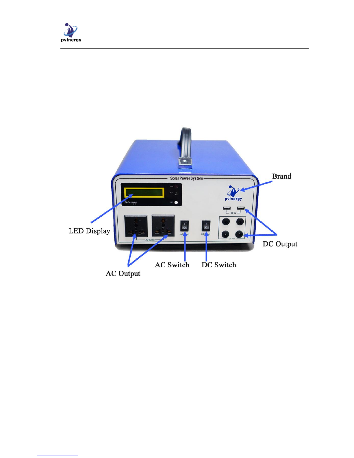
2.1 PVES Appearance Overview.................................................................................................................... - 2 -
2.2 Dimensions and Weights.......................................................................................................................... - 3 -
2.3 System Diagram....................................................................................................................................... - 4 -
3. Installation .................................................................................................................................................... - 4 -
3.1 Notes before Installation .......................................................................................................................... - 4 -
3.2 Checklist of Package................................................................................................................................ - 4 -
3.3 Safety Precautions.................................................................................................................................... - 5 -
4. Circuit Connection ....................................................................................................................................... - 5 -
4.1 Input and Output Terminals...................................................................................................................... - 5 -
4.2 Wiring Diagram under Inverter Mode...................................................................................................... - 6 -
4.3 Wiring Diagram under Charging Inverter Mode ...................................................................................... - 6 -
4.4 System Ground......................................................................................................................................... - 6 -
5. PVES Operation Instruction ....................................................................................................................... - 7 -
5.1 Inverter Mode........................................................................................................................................... - 7 -
5.2 Charing Inverter Mode ............................................................................................................................. - 7 -
6. HMI Instruction ........................................................................................................................................... - 7-
6.1 LCD Display ........................................................................................................................................... - 7 -
7. Alarm Information and Troubleshooting ................................................................................................... - 8 -
7.1 System Failure......................................................................................................................................... - 9 -
8. Technical Data............................................................................................................................................. - 10 -

PVES Series User Manual
Installation and User Manual
- 1 -
1. Symbol Explanation
Danger
High‐voltage risk; Inhibit touching; if not avoided, there will result
in casualties.
Warning
Potential risk; if not avoided, there will result in casualties.
Warning
High temperature; inhibit touching; incaution touching may result in
scald.
Attention
Attention to existing potential risk; if not avoided, could cause the
device not operating properly or property loss.
Attention
It is compliance with WEEE directive.

PVES Series User Manual
Installation and User Manual
- 2 -
2. Product Introduction
2.1 PVES Appearance Overview

PVES Series User Manual
Installation and User Manual
- 3 -
2.2 Dimensions and Weights
Model
Width(mm)
Depth(mm)
Length(mm)
Weight(Kg)
PVES300
255
305
143
5.5
PVES600
255
305
143
5.7
PVES1000
285
335
143
6.0

PVES Series User Manual
Installation and User Manual
- 4 -
2.3 System Diagram
A. Solar Panel: Provide DC power to inverter
B. PVES Inverter: Charging battery via DC power from solar panel(s); Converting DC power from
battery to 220VAC power for loads; Providing 12V/24V and 5V DC input
C. Battery: Charging through controller, storing solar energy and discharging to loads
D. Loads: Divided into AC loads and DC loads, such as fan, TV, computer, light, mobile phone, etc
3. Installation
3.1 Notes before Installation
This user manual describes inverter installation and safety operation. Please follow
below instructions carefully before installation:
To check the ambient temperature for installation, it is recommended from 0℃to 40℃
AC output voltage range: 220Vac±5%, 50Hz
Adequate convection space surrounds the inverter
The inverter is installed far away from explosive vapor
No flammables are near the inverter
Do not expose the PV inverter to direct sunlight
3.2 Checklist of Package
Please go over the items carefully in the box after open the package. The items should contain as
below:
No.
Items
Quantity

PVES Series User Manual
Installation and User Manual
- 5 -
1
PVES300/PVES600/PVES1000 inverter
1
2
12/24V incandescent light with wires
1
3
Length: 1m 6 mm2 cable and battery clamp
1
4
User Manual
1
5
QualityAssurance Card
1
Verify that the above items are complete when open the package
3.3 Safety Precautions
A. Do not disassemble the enclosure. This inverter does not contain user serviceable parts. Refer all
servicing to qualified service personnel. All wiring and electrical installation should be
conducted by the qualified service personnel and must meet CE requirements.
B. AC loads, PV voltage and Bat voltage are terminated inside the PV Inverter. Please disconnect
these circuits before servicing.
C. Energy stored in this equipment’s DC link capacitors presents a risk of electric shock. Even if the
equipment is disconnected from the grid and photovoltaic panels, high voltages may still exist
inside the PV inverter. Do not disassemble the enclosure until at least 5 minutes after
disconnecting all power sources.
D. This inverter is mainly designed for 220V AC loads, 12V/24V and 5V DC loads. Please do not
connect the inverter to grid, otherwise serious damage will be resulted in to the equipment.
E. Attentively take the inverter out from its packaging and inspect for external damage. If any flaw
is found, please contact the local dealers.
4. Circuit Connection
4.1 Input and Output Terminals
Terminal symbols
Function instruction
Quantity
Bat+
Battery anode terminal
1
Bat-
Battery cathode terminal
1
PV+
PV panel anode terminal
1
PV-
PV panel cathode terminal
1
Power
Electric switch for inverter
1

PVES Series User Manual
Installation and User Manual
- 6 -
Terminal symbols
Function instruction
Quantity
AC Switch
Output switch for 220VAC inverter
1
DC Switch
12V/24V and 5V DC output switch
1
DC 5V
5V DC output terminal, USB
connection
2
DC 12V
12V/24V DC output terminal
4
4.2 Wiring Diagram under Inverter Mode
A.Please avoid short-circuit for battery and make sure the polarity is correct before battery
connects to the unit. Incorrect polarity connection could cause permanently damage of the unit.
B.The cathode and anode terminal of battery are connected respectively to the Bat+ and Bat-
terminal of off-grid inverter. Each DC terminal on the inverter can tolerate 100ADC. The
suggested connect wire for positive (+) is red wire, and for negative (-) is black wire.

PVES Series User Manual
Installation and User Manual
- 7 -
4.3 Wiring Diagram under Charging Inverter Mode
A.Before connecting PV panels to PV terminals, please make sure the polarity is correct. Please
avoid short-circuit for battery and make sure the polarity is correct before battery connects to the
unit. Incorrect polarity connection could cause permanently damage of the unit.
B.The cathode and anode terminal of PV panels are connected respectively to the Bat+ and Bat-
terminal of off-grid inverter. Each DC terminal on the inverter can tolerate 50ADC. The suggested
connect wire for positive (+) is red wire, and for negative (-) is black wire.
C.The cathode and anode terminal of battery are connected respectively to the Bat+ and Bat-
terminal of off-grid inverter. Each DC terminal on the inverter can tolerate 100ADC. The
suggested connect wire for positive (+) is red wire, and for negative (-) is black wire.
5. PVES Operation Instruction
PVES series solar residential system can not only under charging inverter mode, but also inverter mode.
5.1 Inverter Mode
A. Connect battery wires pursuant to figure 4.2, the wiring diagram
B. Power switch: Turn the switch on the back of power into on
C. AC output switch: connect to AC switch, providing 220V and 50Hz AC power to loads
D. DC output switch: connect to DC output switch, providing DC output with 12V/24V and 5V
5.2 Charging Inverter Mode
A. Connect the PV and BAT cables pursuant to figure 4.2, the wiring diagram
B. Power switch: Turn the switch on the back of power into on, providing power for battery by
controller
C. AC output switch: connect to AC switch, providing 220V and 50Hz AC power to loads
D. DC output switch: connect to DC output switch, providing DC output with 12V/24V and 5V
Notes:
It is extremely easy to operate the PVES solar residential system. The machine

PVES Series User Manual
Installation and User Manual
- 8 -
works automatically when it is at normal charging. If it needs to support loads, AC Switch and DC Switch
should be operated manually. Besides, in order to achieve maximum conversion efficiency for inverter,
please read below information carefully:
A.Charging mode: inverter is going on three phase charging automatically when it is at normal
charging
B.Adjustment for LCD backlight: for power saving, the LCD backlight will be closed
automatically after 20 seconds
C.Standby mode: in order to save power for battery, it is recommended to turn off AC switch and
DC switch
6. HMI Instruction
6.1 LCD Display
There are 2 LED indicating lights and 1 button in HMI as below:
Contents
Function instruction
Red light(Fault)
Fault when red light is on
Green light(Run)
Run when green light is on
Button(Info)
Press the button and LCD backlight is on
What LCD displays
when system runs
Pv Volt
PV panels voltage
Bat Volt
Battery voltage
Chg Cur
Battery charging current
Out Volt
AC output voltage
Out Cur
AC output current
Out Power
Output power

PVES Series User Manual
Installation and User Manual
- 9 -
Contents
Function instruction
What LCD displays
when system fails
Refer to figure 7.1 for
system failure
Refer to figure 7.1 for system failure
7. Alarm Information and Troubleshooting
PVES series solar residential system has a perfectly complete alarm and protection
function. When system fails, controller can clearly indicate the fault and alarm. Red light is
on and alarmed, and LCD displays what the fault is. Pursuant to the LCD, fault can be rapidly
recognized so that relevant strategy is made to solve it.
7.1 System Failure
System Failure
Reasons
Strategies
AC Fault
Over current
1. Short-circuit for output load
2. Over-load
1. Check the connection for loads
2. Check whether the power of load
exceeds rated output power
3. Please call local service
AC Fault
high temp
1. Fan is failed to work
2. There are too much dust or
block in air inlet or outlet
1. Replace a new fan
2. Dredge the air inlet and outlet
3. Please call local service
AC Fault
low temp
1. Environment temperature is
low
2. No connection for
temperature sensor
1. Put the system on high temperature
2. Please call local service
DC Fault
bat low volt
1. The power of battery is
low
1. Charge the battery
2. Please call local service
DC Fault
bat high volt
1. Over-charge for battery
2. False series number for
battery
1. Over-charge for battery
2. Check series number for battery
AC Fault
out high volt
1. High-voltage forAC output
1. Please call local service
AC Fault
out low volt
1. Low-voltage forAC output
1. Please call local service

PVES Series User Manual
Installation and User Manual
- 10 -
System Failure
Reasons
Strategies
AC Fault
bus high
1. Booster circuit fault
1. Please call local service
AC Fault
bus low
1. Booster circuit fault
2. The voltage for battery
discharges 10.5/20V
1. Please call local service
2. Check whether the power of battery is
enough
AC Fault
out over load
1. Over-load
1. Lower the power of load to rated output
power or less
2. Please call local service
DC Fault
pv high volt
1. High-voltage for PV panels
1. Open circuit for PV panels exceeds its
specification
2. Please call local service
DC Fault
load oc
1. The power of DC 12V/24V
and 5V loads is higher than
their rated power
1. Reduce DC loads
2. Please call local service
DC Fault
Charge over current
1. Charging circuit fault
1. Please call local service
DC Fault
Communication off line
1.Communcation fault
2.No connection for
communication cable
1. Please call local service
8. Technical Data
Model
Technical data
PVES300
PVES600
PVES1000
Output data
Output voltage
220V±5%
220V±5%
220V±5%
Output frequency
300W
600W
1000W
Surge capacity
600VA
1200VA
2000VA
Efficiency
>85%
>85%
>85%
Over-load protection
Yes
Yes
Yes
Short-circuit protection
Yes
Yes
Yes
Waveform
Pure sine wave
Pure sine wave
Pure sine wave
DC
output
USB output
5V /2A
5V /2A
5V /2A
DC output
12V/8A
24V/8A
24V/8A
Input data
PV panel
18V 60W-200W
27V 100W-300W
27V 200W-400W
Battery
Battery voltage
12V
24V
24V
Floating charge
voltage
13.6
27.2
27.2

PVES Series User Manual
Installation and User Manual
- 11 -
Over-charged
protection voltage
16
32
32
PV
controller
Max. Voc
21V
36V
36V
Max. charging
current
10A
10A
10A/20A
Standby power
consumption
0.5W
1W
1W
Environment
Working temperature range
0℃~ +40℃
Storage temperature range
-15℃~ +65℃
Altitude
≤2000m 79.5kPa~ 106kPa
Relative humidity
Non-solidification, relative humidity<90%
Mechanical
Width/ Depth/ Height (mm)
255/305/143
255/305/143
285/335/143
Weight
5.5KG
5.7KG
6.0KG
Standard
CE
Other manuals for PVES300
1
This manual suits for next models
2
Table of contents
Popular Solar Panel manuals by other brands

EmergoPlus
EmergoPlus PowerXtreme SOLAR set XS100 user manual

Astronergy
Astronergy CHSM6610M manual

XUNZEL
XUNZEL PACK ELITE+ Series user manual

Consolar
Consolar EURO L20 installation instructions

Qcells
Qcells Q.POWER-G5.1 Installation and operation manual

Chromasun
Chromasun High?Temperature Thermal Collector System installation manual