GE Oil & Gas 4411 User manual

GE Oil & Gas
4411 Model
Masoneilan* Electropneumatic Transducer
Instruction Manual
GE Data Classification : Public

b | GE Oil & Gas © 2015 General Electric Company. All rights reserved.

Masoneilan Model 4411 Electropneumatic Transducer Instruction Manual | c
© 2015 General Electric Company. All rights reserved.
THESE INSTRUCTIONS PROVIDE THE CUSTOMER/OPERATOR WITH IMPORTANT PROJECT-
SPECIFIC REFERENCE INFORMATION IN ADDITION TO THE CUSTOMER/OPERATOR’S NORMAL
OPERATION AND MAINTENANCE PROCEDURES. SINCE OPERATION AND MAINTENANCE
PHILOSOPHIES VARY, GE (GENERAL ELECTRIC COMPANY AND ITS SUBSIDIARIES AND AFFILIATES)
DOES NOT ATTEMPT TO DICTATE SPECIFIC PROCEDURES, BUT TO PROVIDE BASIC LIMITATIONS
AND REQUIREMENTS CREATED BY THE TYPE OF EQUIPMENT PROVIDED.
THESE INSTRUCTIONS ASSUME THAT OPERATORS ALREADY HAVE A GENERAL UNDERSTANDING
OF THE REQUIREMENTS FOR SAFE OPERATION OF MECHANICAL AND ELECTRICAL EQUIPMENT
IN POTENTIALLY HAZARDOUS ENVIRONMENTS. THEREFORE, THESE INSTRUCTIONS SHOULD BE
INTERPRETED AND APPLIED IN CONJUNCTION WITH THE SAFETY RULES AND REGULATIONS
APPLICABLE AT THE SITE AND THE PARTICULAR REQUIREMENTS FOR OPERATION OF OTHER
EQUIPMENT AT THE SITE.
THESE INSTRUCTIONS DO NOT PURPORT TO COVER ALL DETAILS OR VARIATIONS IN EQUIPMENT
NOR TO PROVIDE FOR EVERY POSSIBLE CONTINGENCY TO BE MET IN CONNECTION WITH
INSTALLATION, OPERATION OR MAINTENANCE. SHOULD FURTHER INFORMATION BE DESIRED
OR SHOULD PARTICULAR PROBLEMS ARISE WHICH ARE NOT COVERED SUFFICIENTLY FOR THE
CUSTOMER/OPERATOR'S PURPOSES THE MATTER SHOULD BE REFERRED TO GE.
THE RIGHTS, OBLIGATIONS AND LIABILITIES OF GE AND THE CUSTOMER/OPERATOR ARE
STRICTLY LIMITED TO THOSE EXPRESSLY PROVIDED IN THE CONTRACT RELATING TO THE SUPPLY
OF THE EQUIPMENT. NO ADDITIONAL REPRESENTATIONS OR WARRANTIES BY GE REGARDING
THE EQUIPMENT OR ITS USE ARE GIVEN OR IMPLIED BY THE ISSUE OF THESE INSTRUCTIONS.
THESE INSTRUCTIONS ARE FURNISHED TO THE CUSTOMER/OPERATOR SOLELY TO ASSIST
IN THE INSTALLATION, TESTING, OPERATION, AND/OR MAINTENANCE OF THE EQUIPMENT
DESCRIBED. THIS DOCUMENT SHALL NOT BE REPRODUCED IN WHOLE OR IN PART WITHOUT
THE WRITTEN APPROVAL OF GE.

d | GE Oil & Gas © 2015 General Electric Company. All rights reserved.
Safety Warning�������������������������������������������������������������������������������������������������������������������������������������������������������������������� 1
Brief User Guide ������������������������������������������������������������������������������������������������������������������������������������������������������������������ 2
General Description ����������������������������������������������������������������������������������������������������������������������������������������������������������� 2
Instrument Mounting��������������������������������������������������������������������������������������������������������������������������������������������������������� 3
Captured Bleed Version �����������������������������������������������������������������������������������������������������������������������������������������������������3
Pneumatic Installation������������������������������������������������������������������������������������������������������������������������������������������������������ 3
Electrical Installation��������������������������������������������������������������������������������������������������������������������������������������������������������� 4
Wiring and Cable Entry �����������������������������������������������������������������������������������������������������������������������������������������������������4
Conduit Entry ��������������������������������������������������������������������������������������������������������������������������������������������������������������������������4
Calibration �������������������������������������������������������������������������������������������������������������������������������������������������������������������������������4
Tight Shut-Off Adjustment Instructions����������������������������������������������������������������������������������������������������������������������� 5
Simple Functional Checks ������������������������������������������������������������������������������������������������������������������������������������������������ 5
Technical Specifications ��������������������������������������������������������������������������������������������������������������������������������������������������� 6
Performance������������������������������������������������������������������������������������������������������������������������������������������������������������������������� 6
Potentially Explosive Atmospheres — Markings�������������������������������������������������������������������������������������������������������� 7
Instructions Specific to Hazardous Area Installations��������������������������������������������������������������������������������������������� 8
Instructions — Special Condition for Safe Use����������������������������������������������������������������������������������������������������������� 8
FM Control Drawing����������������������������������������������������������������������������������������������������������������������������������������������������������� 9
CSA Control Drawing �������������������������������������������������������������������������������������������������������������������������������������������������������10
Table of Contents

Masoneilan Model 4411 Electropneumatic Transducer Instruction Manual | 1
© 2015 General Electric Company. All rights reserved.
Safety Information
Important - Please Read Before Installation
These instructions contain DANGER, WARNING, and CAUTION
labels, where necessary, to alert you to safety related or other
important information� Read the instructions carefully before
installing and maintaining your control valve� DANGER and
WARNING hazards are related to personal injury� CAUTION
hazards involve equipment or property damage� Operation
of damaged equipment can, under certain operational
conditions, result in degraded process system performance
that can lead to injury or death� Total compliance with all
DANGER, WARNING, and CAUTION notices is required for
safe operation�
This is the safety alert symbol� It alerts you to potential
personal injury hazards� Obey all safety messages that
follow this symbol to avoid possible injury or death�
Indicates a potentially hazardous situation which, if not avoided,
could result in death or serious injury�
Indicates a potentially hazardous situation which, if not avoided,
could result in serious injury�
Indicates a potentially hazardous situation which, if not avoided,
could result in minor or moderate injury�
When used without the safety alert symbol indicates a
potentially hazardous situation which, if not avoided, could
result in property damage�
Note: Indicates important facts and conditions�
Warranty
Items sold by General Electric are warranted to be free from
defects in materials and workmanship for a period of one
year from the date of shipment provided said items are used
according to GE recommended usages� GE reserves the right
to discontinue manufacture of any product or change product
materials, design or specifications without notice�
This instruction manual applies to the Masoneilan 4411 IP
Transducer�
Note:
• The 4411 IP Transducer MUST BE installed, put
into service and maintained by qualified and
competent professionals who have undergone
suitable training�
• Under certain operating conditions, the use of damaged
equipment could cause a degradation of the performance
of the system which may lead to personal injury or death�
• Changes to specifications, structure, and components used
may not lead to the revision of this manual unless such
changes affect the function and performance of the product�
• All surrounding pipe lines must be thoroughly flushed to ensure
all entrained debris has been removed from the system�
IMPORTANT: SAFETY WARNING
Please read these instructions carefully BEFORE this instrument
is installed or maintained�
These converters are intended for use in industrial
compressed air systems only� Ensure that adequate pressure
relief provision is installed if application of system supply
pressure could cause downstream equipment to malfunction�
Installation should be in accordance with local and national
compressed air and instrumentation codes�
Products certified for use in explosion-proof or intrinsically
safe installations MUST:
a) Be installed in accordance with local and national codes
for hazardous area installations, and in accordance
with this manual�
b) Only be used in situations which comply with the
certification conditions stated in this handbook�
c) Only be maintained by qualified personnel with adequate
training on hazardous area implementation�
Before using these products with fluids other than air or for non-
industrial applications consult GE�
About this Manual
• The information in this manual is subject to change without
prior notice�
• The information contained in this manual, in whole or part,
shall not be transcribed or copied without Masoneilan’s
written permission�
• Please report any errors orquestions about the information
in this manual to your local supplier�
• These instructions are written specifically for the 4411 IP
Transducer, and do not apply for other instruments or IP
transducers outside of this product line�

2 | GE Oil & Gas © 2015 General Electric Company. All rights reserved.
Brief User Guide
This is a quick guide to connecting the instrument for the conven-
ience of personnel who are familiar with this type of product�
More comprehensive instructions are contained later in this
manual:
1. Connect a clean air supply of about 2�0 bar (30 psig for
the 3-15 psig output model, or 2�4 bar (35 psig) for the
6-30 psig output model) to the IN port (1/4" NPT)�
2. Connect a pressure gauge or actuator to the OUT port�
DO NOT use PTFE tape or similar to seal the ports� Use
a minimum of soft setting anaerobic compound, e�g�
Loctite Hydraulic Seal 542�
3. Unscrew the lid to obtain access to the terminals�
The cable will need to be sealed by an approved gland
for explosion-proof installation�
The second un-used conduit entry must be sealed with
an explosion-proof blanking plug�
4. Connect a 4-20mA current source, either through the Jack-
Plug source or Terminal connections� Ensure that it can
supply at least 6�5V at 20mA� Check for correct polarity�
DO NOT use a voltage source; it will irreversibly damage
the converter�
5. Switch on the air supply and current source and allow a
few seconds stabilisation time� Adjust span and zero via
the trimpots if necessary�
If the instrument fails to operate refer to the Simple Functional
Checks�
General Description
These converters are precision electronic pressure controllers
designed for continuous process control applications� The units
operate a closed loop system incorporating a feedback sensor
ensuring long-term stability and high accuracy performance,
with ‘fail-safe’ operation, i�e� the output falls to a low pressure
upon failure of the loop current�
These instruments combine substantial flow capacity, with the
ability to give precise control into closed volume ‘dead end’
applications�
The instrument has been designed to withstand the rigours
of industrial environments; such as shock, vibration and
positional effects� As with any other precision instrument
dropping the unit onto a hard surface may result in shifts in
calibration or possibly permanent damage� The unit may be
mounted directly upon a control valve� A mounting bracket is
provided for surface mounting, or the instrument may be fixed
directly to rigid pipework�
The electronics are enclosed within a watertight housing,
which is suitable for outdoor use if a suitable cable gland is
used� The lid should be firmly tightened, the use of a tool for
this purpose is not recommended�
Figure 1
JACK SOCKET: TO CALIBRATE UNIT ON
INSTALLATION USING A 4-20MA INPUT SIGNAL�
WHEN USING JACK PLUG A SIGNAL DOES NOT HAVE
TO BE SUPPLIED VIA THE TERMINAL BLOCK� THE
INPUT SIGNAL CAN BE MONITORED THROUGH THE
JACK PLUG SOCKET WHEN UNIT IS IN OPERATION�
1/2"NPT or M20
Conduit Entry
3�5mm Jack Socket
Alternative Power
Supply & Monitor
Span
Zero
Tight Shut Off
4-20mA Input Terminals
1/2"NPT or M20
Conduit Entry
Lid Locking
External Earth
1/8" Gauge Port
External Earth
Air Filter;
DO NOT REMOVE WHEN PRESSURIZED�
DO NOT USE WITH FILTER REMOVED�
Air Filter� BS2000 with 98% efficiency @
2µM with water and oil absorption�
Internal Earth

Masoneilan Model 4411 Electropneumatic Transducer Instruction Manual | 3
© 2015 General Electric Company. All rights reserved.
To meet the EMC specifications, screened cable should be used
for installation� The cable screen should be connected to the
internal earth bonding point of the I/P� An earth strap should
also be connected from the external earth bonding point of
the I/P to a common earth point� The cable screen should not
be connected at the signal source when used in Intrinsically
Safe (IS) environments� The I/P has been thoroughly tested in
accordance with:
Electromagnetic compatibility (EMC)
Generic Standards – Immunity for industrial environments
Electromagnetic compatibility (EMC)
Generic Emissions Standard – Industrial environment
Please consult wiring diagram for further information� The
results obtained from these tests show that with the screen
arrangement shown in the installation diagram, the typical
sustained output pressure shift is <+/-5% full scale� Consult
supplier for further details�
Instrument Mounting
The converter can be mounted directly onto a valve, onto any
suitable flat surface, or onto 2” (50mm) pipe� Dimensional details:
Figure 2
These converters will operate in any position, with slight
re-calibration adjustments, normal operation is in the upright
position, i�e� with the screwed lid horizontal� The unit is weather
resistant when the lid is removed for connection or calibration,
but should not be left uncovered during operation or for
extended periods of time� They are unaffected by shock and
vibration, but severe vibration environments are best avoided�
The instruments are protected against environmental effects,
to a level of Type 4X (IP66)� Sensible positioning should be used
if the local environment is severe�
Temperature compensation is designed into these converters
which will operate over a range from –40° to +85°C (-40° to
+185°F)� Maximum life is obtained if extreme temperature cycling
is avoided� In extreme direct sunlight, sun-shading is advised�
The pneumatic exhaust and the bleed are routed through the
baffles� The baffles must not be blocked with paint and/or
plastic sheeting etc�
Captured Bleed Version
The baffles and the baffle cover are fitted to maintain the
adequate Ingress Protection (IP) rating of the instrument�
Removal of these protective parts will invalidate the IP and the
NEMA 4X rating of the instrument�
For captured bleed installation, remove the baffle cover and
unscrew both the baffles, fit 1/8" NPT fittings to two separate
lengths of pipes, to exhaust and bleed gas to a safe area
installation�
Vented gas from the enclosure through bleed port must not
be re-circulated and introduced back into the process stream�
Exhaust port installation must not have any restriction to
create backpressure to cause instrument to malfunction�
Instrument installation for captured bleed version must be
under the installer’s discretion�
Note: Exhaust Port is nearer the conduit entry (LH side)
Enclosure Bleed Port is on the RH side. (See Figure 3.)
Figure 3
Pneumatic Installation
These instruments are recommended for use with clean, dry,
oil free instrument grade air to BS�6739:1986 or ANSI/ASA-57�3
1975 (R1981)�
Dew Point: At least 10°C (18°F) below (-40°C) minimum
anticipated ambient temperature�
Dust: Filtered to below 50 microns�
Oil Content: Not to exceed 1ppm mass�
The instrument is factory calibrated with a supply pressure of 30
psig (2 bar) ±10%� Operation is possible at any pressure between
18 and 150 psig (1�3 to 10 bar), though recalibration may be
necessary towards these limits to maintain specified accuracy�
The inlet and outlet ports are threaded 1/4" NPT female and
suitable fittings should be used� For most installations 1/4"
(6mm) pipe will be adequate� If a large actuator, high flow
rates or long pipework is necessary then a larger diameter
should be used�
Plastic tubing, e�g� Nylon is preferable where circumstances
permit, since it is normally very clean internally� In all cases,
purge the supply pipework before connection to the converter�
Two gauge ports are provided to facilitate direct mounting of
a pressure gauge� To use one of these ports remove the plug
(using a 1/4" or 3/16" Hexagon Key) in a de-pressurized state,
and connect the gauge� The ports are threaded 1/4" NPT at
the back of the unit and 1/8" NPT at the front�
Exhaust Port Enclosure Bleed Port

4 | GE Oil & Gas © 2015 General Electric Company. All rights reserved.
Under no circumstances should PTFE tape be used for sealing
the fittings as this tends to shred small particles which may
find their way into the instrument causing malfunctions�
The use of a soft setting anaerobic hydraulic seal is
recommended, (e�g� Loctite Hydraulic Seal 542)� Follow the
manufacturers recommendations�
Do not use an excessive amount as this will not set and could
find its way into the instrument�
If the air supply is not of adequate quality, the device
performance can be affected� Adequate quality can normally
be achieved by the use of air filter regulators�
Electrical Installation
The electrical connections should be made as shown in the
dimensional drawing Figure 1� The instrument is protected
against reverse polarity to –100mA, no operation is possible
in this condition�
The Model 4411 approximates a constant voltage load of 6�5
volts across the loop terminals, therefore it is essential that the
loop controller be capable of providing a constant current in
the range 4-20mA with an output voltage of at least 6�5 volts�
Voltage output controllers (e�g� variable voltage power
supplies) are entirely unsuitable for the Model 4411 and could
severely damage the electronic circuits�
Important Note
The control electronics of the Model 4411 incorporate precision
electronics� The calibration of the unit may be affected by very
high voltage spikes� Consequently, in environments where static
electricity may be present ESD precautions should be used�
Wiring And Cable Entry
These instruments must be installed in accordance with local
and national codes of practice, especially for hazardous
area installations� The instruments are fully isolated from
ground and therefore grounding is unnecessary for functional
purposes� However, grounding may be necessary to conform
to installation codes�
Note: It is strongly recommended that shielded cable or
a grounded conduit be used to achieve maximum RFI
immunity, if the installation has any risk of electromagnetic
interference.
Conduit Entry
The instrument has twin conduit entry threaded 1/2" NPT� For
explosion proof installation, a sealed conduit gland conforming
to explosion-proof specifications must be used� A ground
terminal is provided both internally and externally and should
be used if ground continuity is essential�
The unit is supplied with plastic blanking plugs, which must
be removed before operation/calibration and replaced with a
blanking plug conforming to the hazardous area certification
rating applicable�
Calibration
The instruments are designed for continuous operation
without the necessity for routine overhaul, with continuous
monitoring, adequate precautions and replacement of the
filter no longer than every 5 years�
The most common source of failure for pneumatic
instrumentation has been found to be inadequate air quality,
allowing contaminants to block internal orifices� Air filtering is
included within the instrument but cannot cope with sustained
poor air quality, which may ultimately lead to failure�
The recommendations in the Pneumatic Installation section
should be rigorously observed�
Note: These instruments are factory calibrated at a supply
pressure of 30psig (2 bar).
The instrument cover must be unscrewed to obtain access to
the trimpots�
Do not remove the instrument cover in a potentially explosive
atmosphere when the instrument is powered�
An accurate current source of 4-20mA and pressure gauge are
required� These should be of good quality with an accuracy of
0�1% or better� The current source should be checked to ensure
that it provides at least 6�5V at 20mA output compliance�
• Connect the instrument as described in the installation
section or the test-jack section below�
• Remove the instrument cover to gain access to the
trimpots and jack-socket�
• Set the current to 4�00mA – the instrument outlet should
be 3�00+/-0�05psig (0�200+/-0�003 bar)� Adjust the Zero
trimpot if necessary�
• For 6-30 psig output, the output pressure should be set
to 6�00 ±�05 psig (0�400 ± �003 bar)� Adjust trimpot as
necessary�
• Set the current source to 20�00mA – the instrument outlet
should be 15�00 +/-0�05psig (1�00+/-0�003 bar)� Adjust the
Span trimpot if necessary�
• For 6-30 psig output, the output pressure should be set
to 30�00 ±�05 psig (2�00 ± �003 bar)� Adjust trimpot as
necessary�
If either Span or Zero controls are adjusted it may be
necessary to repeat the above steps until both ends are within
the calibration limits�
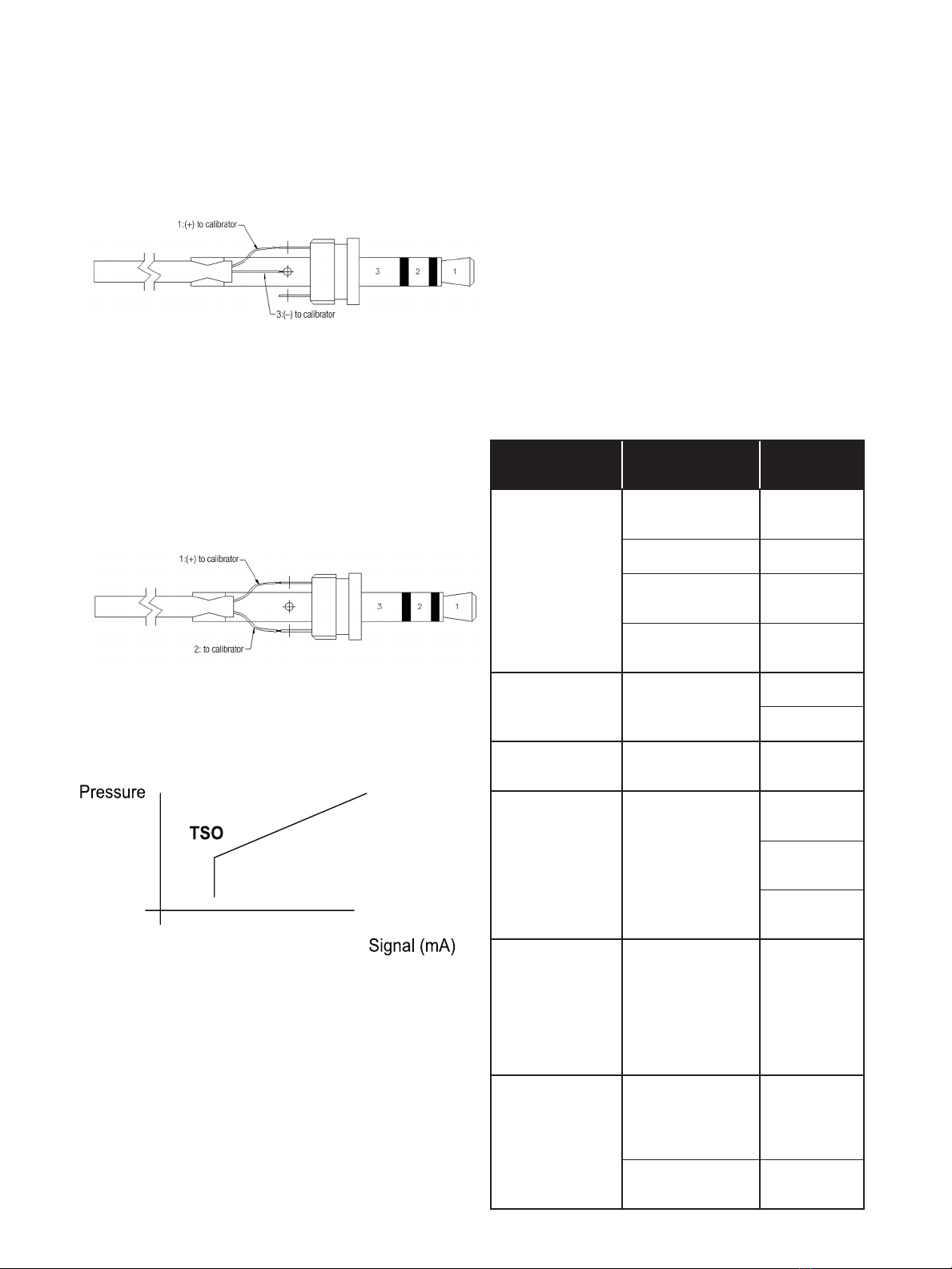
Alternatively the Jack Plug can be connected to calibrate and
test the unit� The Jack Plug can be either set-up for Monitoring
or Calibration/Operation set-up�

Masoneilan Model 4411 Electropneumatic Transducer Instruction Manual | 5
© 2015 General Electric Company. All rights reserved.
Calibration with the Test Jack:
Connect pin 1 of the Jack Plug to the positive (+) lead of the
current calibrator and pin 3 of the Jack Plug to the negative
(-) lead of the current calibrator and then insert the Jack Plug
into the Test Jack� The current calibrator is now the input
signal source� Calibrate as stated above� Removing the Jack
Plug will return operation of the unit back over to the original
current source�
Figure 4
Monitoring with the Test Jack:
Connect pin 1 of the Jack Plug to the negative (-) lead of the
ammeter and pin 2 of the Jack Plug to the positive (+) lead of
the ammeter� Insert the Jack Plug into the Test Jack and use
the ammeter to monitor the input current loop�
Tight Shut-Off Adjustment
Instructions
Figure 5
The Tight Shut-Off potentiometer can be adjusted to set the
zero point at which the instrument ‘shuts off’�
For Example:
Tight shut-off is deactivated in the factory.
Figure 6
Setting of shut-off point:
1. With the instrument under test connected to the required
supply pressure and load ports, apply a demand current
signal of that value at which shut-off is required�
2. If the output pressure is >start-up pressure (~0psi),
adjust potentiometer slowly clockwise until the output
pressure falls to zero� Do not turn the pot beyond this
point� The shut-off point is now set�
Shut-off point check:
Increase the input signal by approximately 0�5mA (e�g� to
3�8mA) the output pressure will rise above 0psi� Reset the input
signal to the required shut off point (e�g� 3�3mA) and the output
pressure will fall to zero�
Simple Functional Checks
Apply a 4-20mA signal and an air supply of 30psig and observe
the output on a pressure gauge� It should control smoothly�
The Test Jack can also be connected as a monitor measure�
Problem Possible Causes Suggested
Action
Maximum output
not available
Supply pressure
too low
Check and
adjust supply
Calibration error Recalibrate
Air leak in
instrument
Locate leak
and repair
Excess outlet flow Check with
specification
Minimum output
too high
Calibration error Replace
Recalibrate
Delay on
start up
A delay of a few
seconds is normal
None
Erratic operation
at low pressure
Signal currents
below 3�5mA are
insufficient for
normal operation
Increase
current
May need
recalibration
Tight shut-off
set
No output
available
Tight shut off
potentiometer
adjusted
Turn until
a pressure
output is
observed
on gauge
or pressure
sensor
Erratic at all
pressures
Controller cannot
provide 6�5V
continuously
Reduce loop
resistance
or change
controller
Contamination Check I/P
filter status

6 | GE Oil & Gas © 2015 General Electric Company. All rights reserved.
Technical Specifications
Functional
Input: 4-20mA (0-100%)
Output: 3-15psi and 15-3 psi or 6-30 psi and 30-6 psi
Minimum output greater than 0�2psi
Supply Pressure: 150psi maximum, minimum 3psi above max required output pressure
Supply Pressure Effect: Span over full supply pressure range <0�1%
Medium: Standard instrument quality air to 50 micron
Air Consumption: <2�5l/min (0�09 scfm) at 50% signal
Operating Temperature: -40°C to 85°C (-40° F to +185° F)
Relative Humidity: 0 to 100% Relative Humidity
Output Capacity: >300l/min (12scfm) delivery and exhaust at 100% signal
Maximum Terminal Voltage: Maximum 6�5Volts
Minimum Operating Current: Less than 3�5mA
Current Reversal Protection: No effect within normal 4-20mA range protected to 100mA continuous�
Insulation: Electrical circuits are isolated from housing� Tested to 725V DC, 100MΩ
Performance
(At 20°C (68°F), 30psi supply, 3-15psi range, for a typical instrument except otherwise stated);
Instrument Accuracy: mean <0�1%
Independent Linearity: mean <±0�05% of span
Hysteresis, Resolution & Deadband: mean <=0�05% of span
Accuracy Rating: <±0�75% span (including factory calibration error)
Above figures are in accordance with ANSI/ISA 51.1:1993; N.B. Instrument accuracy excludes calibration errors
Temperature Effect: Span and Zero
Mean temperature coefficient over full operating range –40 to +85°C less than 0�035%
span/degC
Vibration: <3% of span; 4mm peak-peak 5-15Hz, 2g sine 15-150Hz
Mounting Position: Integral bracket allows for mounting in any orientation
Long Term Stability: Span and Zero
Typically better than 0�25% span per year
Electromagnetic Compatibility: Compliant with EC requirements:
BS EN50081-2: EMC - Generic Emissions Standard – Industrial environment
BS EN61000-6-2: EMC - Generic Standards – Immunity for industrial environments
To meet the EMC specifications, screened cable should be used for installation� The
cable screen should be connected to the internal earth bonding point of the I/P� An
earth strap should also be connected from the external earth bonding point of the
I/P to a common earth point� The cable screen should not be connected at the signal
source when used in IS environments�
Controls: Span and Zero and tight shut-off trimpots with 10% adjustment
Physical
Air Supply and Output Connections: 1/4"NPT supply and output; 1/8"NPT exhaust baffles to allow for captured bleed
Electrical: 1/2"NPT (M20 option); 2 internal screw terminals for 2�5mm2cable
Weight: 2�07Kg
Materials
Aluminium and zinc diecasting with nitrile diaphragms, epoxy powder coat painting as standard� Weatherproof to Type 4X (IP66)
[mounted upright]�

Masoneilan Model 4411 Electropneumatic Transducer Instruction Manual | 7
© 2015 General Electric Company. All rights reserved.
Potentially Explosive Atmospheres - Markings:
Certification
Agency
Flame Proof /
Explosion Proof Intrinsically Safe Type nL, nA
Non-Incendive Others
SIRA ATEX
Approved
To EN60079
Sira 01ATEX1223
Ex d IIC T4 Gb
(Ta = -20° to +40°C)
Ex d IIB+H2T5 Gb
(Ta = -20° to +80°C)
Ex d IIB+H2T6 Gb
(Ta = -20° to +65°C)
Ex t IIIC T95°C Db
(Ta = -20° to +85°C)
Umax = 30Vdc
II
2GD
2GD
Sira 01ATEX2224X
Ex ia IIC T4 Ga
Ex ia IIIC Da T95°C
(Ta = -40° to +85°C)
Ui = 30Vdc
Ii = 110mA
Pi = 0�84W
Ci = 6nF
Li = 100µH
II
2GD
1GD
Sira 01ATEX4225X
Ex nA nL IIC T5 Gc
(Ta = -40° to +85°C)
Umax = 30Vdc
Ii = 24mA
Ci = 6nF
Li = 100µH
II 3G
3G
Factory Mutual Class I, Division 1,
Group BCD�
T6 Ta = 75°C,
T5 Ta = 85°C�
Class I, II & III,
Division 1,
Group ABCDEFG�
T4 Ta = 85°C�
Vmax = 30Vdc
Imax = 110mA
Ci = 0�006µF
Li = 100µH
Install as per Control
drawing 2001-082�
Class I, Division 2,
Group ABCD�
T6 Ta = 75°C,
T5 Ta = 85°C�
Dust Ingress Protection:
Class II & III, Division 1,
Group EFG�
T6 Ta = 75°C,
T5 Ta = 85°C�
Suitable for:
Class II, Division 2,
Group FG,
T6 Ta = 75°C,
T5 Ta = 85°C; and
Class III, Division 1 & 2�
CSA
Class I, Division 1,
Group BCD�
Ta = -40°C to +85°C; T5
Ta = -40°C to +65C; T6
Ex ia, Class I, Division 1,
Group ABCD�
Ta = -40°C to +85°C; T4
Vmax = 30Vdc
Imax = 100mA
Pmax = 0�75W
Ci = 10�5nF
Li = 100µH
(30Vdc max, 300 Ohms)�
Install as per Control
drawing 2001-083�
Class I, Division 2,
Group ABCD�
Ta = -40°C to +85°C; T5
Ii = 24mA
Ci = 6nF
Li = 100µH
NOTE: Because of standard updates, product changes or improvements, certification level may have changed and the
manual may have not been updated yet.
Please refer to device label to check updated certification level.

8 | GE Oil & Gas © 2015 General Electric Company. All rights reserved.
Instructions Specific to
Hazardous Area Installations
(Reference European ATEX Directive 94/9/EC, Annex
II, 1.0.6)
The following instructions apply to equipment covered by
certificate numbers SIRA 01ATEX2224X, SIRA 01ATEX4225X &
SIRA 01ATEX1223
1. The Model 4411 is Triple Certified, and may be installed
as intrinsically safe, flameproof or Type n:
• Zone 0 or 20 installations require the equipment to be
installed as intrinsically safe via suitable associated
apparatus�
• Zone 1 or 21 installations require the equipment to be
installed as intrinsically safe or flameproof; if installed
as flameproof, associated apparatus is not required,
but there are more onerous requirements for cable
entry – refer to EN60079-0�
• Zone 2 or 22 installations may be intrinsically safe,
flameproof or Type n�
• It is recommended that the installer indicates on the
equipment which certification code applies�
2. The equipment should not be used outside the stated
ambient temperature range�
3. The equipment has not been assessed as a safety-
related device (as referred to by Directive 94/9/EC Annex
II, clause 1�5)�
4. Installation and maintenance of this equipment shall be
carried out by suitably-trained personnel in accordance
with the applicable codes of practice (EN 60079-14 and
EN 60079-17 within Europe)�
5. Repair of this equipment shall be carried out by the
manufacturer or in accordance with the applicable code
of practice (IEC 60079-19)�
6. When installing the equipment as flameproof cable
gland (M20 parallel thread) or a conduit (1/2" NPT
tapered thread), the installer should verify the thread
form and ensure that the appropriate matching thread
is used� The pneumatic connections are not flameproof
entries�
7. The certification of this equipment relies on the following
materials used in its construction:
Enclosure: aluminium alloy and zinc alloy
O-ring: nitrile rubber
Encapsulant: polyurethane
If the equipment is likely to come into contact with aggressive
substances, then it is the responsibility of the user to take
suitable precautions that prevent it from being adversely
affected, thus ensuring that the type of protection is not
compromised�
• Aggressive substances: e�g� acidic liquids or gases that
may attack metals, or solvents that may affect polymeric
materials�
• Suitable precautions: e�g� regular checks as part of
routine inspections or establishing from the material’s
data sheet that it is resistant to specific chemicals�
• Not to be used with pure oxygen or oxygen enriched
media as the process fluid�
Consult the supplier for approval certificates�
8� Only approved cable glands are to be used which must
maintain an Ingress Protection of IP66�
9� Unused entry port hole must be blanked off using
suitably approved blanking plug�
Instructions – Special Condition for Safe
Use
For Certificate Number Sira 01ATEX1223 –
(Ex d) None�
For Certificate Number Sira 01ATEX2224X – (Ex ia)
1� For operation reasons, it may be necessary to connect the
screen of the cable to the enclosure of the equipment in
the hazardous area� If this is the case, then the equipment
shall be installed in accordance with EN 60079-14:2008
(specifically clause 12�2�2�3 and 12�2�4), typically using a
galvanically-isolated interface with no other connection
to Earth apart from via the enclosure of the equipment�
2� The enclosure is made from light metal which could cause
ignition due to impact and friction� This shall be taken
into consideration when the apparatus is installed in
location that specifically requires equipment protection
level Ga�
3� Under certain extreme circumstances, the non-metallic
parts incorporated in the enclosure of this equipment
may generate an ignition-capable level of electrostatic
charge� Therefore, when it is used for applications that
specially require equipment protection level Ga, the
equipment shall not be installed in a location where the
external conditions are conductive to the build-up of
electrostatic charge on such surfaces� Additionally, the
equipment shall only be cleaned with a damp cloth�
4� The option for the air vented from the enclosure to be
re-circulated and introduced back into the process
stream shall not be used when the equipment is installed
in locations that specifically require equipment protection
level Ga for group II category 1G or 1D for group III
category 1D equipment�
For Certificate Number Sira 01ATEX4225X –
(Ex nL, nA)
1� When the equipment is energised, it shall only be opened
to connect the jack socket if flammable gases or vapours
are not present�
2� Provisions must be made externally to limit the supply
transient from exceeding 40% of the rated input voltage
(30V)�
3� The apparatus enclosure has a plastic part which may
present a risk of ignition due to a build up of electrostatic
charge� The plastic part must not be rubbed and only
cleaned by using a damp cloth�

Masoneilan Model 4411 Electropneumatic Transducer Instruction Manual | 9
© 2015 General Electric Company. All rights reserved.

© 2015 General Electric Company. All rights reserved.

Masoneilan Model 4411 Electropneumatic Transducer Instruction Manual | 11
© 2015 General Electric Company. All rights reserved.
Notes:

AUSTRALIA
Brisbane:
Phone: +61-7-3001-4319
Fax: +61-7-3001-4399
Perth:
Phone: +61-8-6595-7018
Fax: +61 8 6595-7299
Melbourne:
Phone: +61-3-8807-6002
Fax : +61-3-8807-6577
BELGIUM
Phone: +32-2-344-0970
Fax: +32-2-344-1123
BRAZIL
Phone: +55-11-2146-3600
Fax: +55-11-2146-3610
CHINA
Phone: +86-10-5689-3600
Fax: +86-10-5689-3800
FRANCE
Courbevoie
Phone: +33-1-4904-9000
Fax: +33-1-4904-9010
GERMANY
Ratingen
Phone: +49-2102-108-0
Fax: +49-2102-108-111
INDIA
Mumbai
Phone: +91-22-8354790
Fax: +91-22-8354791
New Delhi
Phone: +91-11-2-6164175
Fax: +91-11-5-1659635
ITALY
Phone: +39-081-7892-111
Fax: +39-081-7892-208
JAPAN
Chiba
Phone: +81-43-297-9222
Fax: +81-43-299-1115
KOREA
Phone: +82-2-2274-0748
Fax: +82-2-2274-0794
MALAYSIA
Phone: +60-3-2161-0322
Fax: +60-3-2163-6312
MEXICO
Phone: +52-55-3640-5060
THE NETHERLANDS
Phone: +31-15-3808666
Fax: +31-18-1641438
RUSSIA
Veliky Novgorod
Phone: +7-8162-55-7898
Fax: +7-8162-55-7921
Moscow
Phone: +7 495-585-1276
Fax: +7 495-585-1279
SAUDI ARABIA
Phone: +966-3-341-0278
Fax: +966-3-341-7624
SINGAPORE
Phone: +65-6861-6100
Fax: +65-6861-7172
SOUTH AFRICA
Phone: +27-11-452-1550
Fax: +27-11-452-6542
SOUTH & CENTRAL
AMERICA AND THE CARIBBEAN
Phone: +55-12-2134-1201
Fax: +55-12-2134-1238
SPAIN
Phone: +34-93-652-6430
Fax: +34-93-652-6444
UNITED ARAB EMIRATES
Phone: +971-4-8991-777
Fax: +971-4-8991-778
UNITED KINGDOM
Bracknell
Phone: +44-1344-460-500
Fax: +44-1344-460-537
Skelmersdale
Phone: +44-1695-526-00
Fax: +44-1695-526-01
UNITED STATES
Massachusetts
Phone: +1-508-586-4600
Fax: +1-508-427-8971
Corpus Christi, Texas
Phone: +1-361-881-8182
Fax: +1-361-881-8246
Deer Park, Texas
Phone: +1-281-884-1000
Fax: +1-281-884-1010
Houston, Texas
Phone: +1-281-671-1640
Fax: +1-281-671-1735
DIRECT SALES OFFICE LOCATIONS
GEA19084C 07/2015
* Denotes a trademark of General Electric Company�
Other company names and product names used in this
document are the registered trademarks or trademarks
of their respective owners�
© 2015 General Electric Company� All rights reserved�
Table of contents
Other GE Oil & Gas Transducer manuals
Popular Transducer manuals by other brands

S+S Regeltechnik
S+S Regeltechnik THERMASGARD MWTM Operating Instructions, Mounting & Installation

Ametek
Ametek Gemco 953 Series installation manual

Balluff
Balluff BTL6-V11V Series Configuration manual

bk ultrasound
bk ultrasound 8816 user guide

Setra Systems
Setra Systems Multi-Sense 231RS operating instructions

Airmar
Airmar P79 Owner's guide & installation instructions

Humminbird
Humminbird Portable Transducer Installation

Lowrance
Lowrance StructureScan installation manual

Airmar
Airmar B240 Owner's guide & installation instructions

Mianyang Weibo Electronic
Mianyang Weibo Electronic WBI122S01 user manual

Ziegler
Ziegler CON-M 22 operating manual

SSET
SSET CE-VJ31A -MSK- 0.5 Series quick start guide