GE ASH218JCDDA User manual

READ CAREFULLY.
KEEP THESE INSTRUCTIONS.
31-5000560 Rev. 5 11-22 GEA
Ductless Multi Zone with
Highwall Indoor Units
Installation
Instructions
Designmayvarybymodelnumber.
Thisinstallationmanualisonly
printedinEnglish.ForFrenchor
Spanishversion,pleasevisit
GEAppliancesairandwater.com
L’aspectpeutvarierselonlenumérodemodèle.
Cemanueld’installationestuniquement
impriméenanglais.Pourlaversionfrançaiseou
espagnole,visitezlesite
GEAppliancesairandwater.com
Eldiseñopuedevariarsegúnelnúmerodemodel.
Estemanualdeinstalaciónsólofueimpresoen
inglés.Paraaccederalaversiónenfrancéso
español,porfavorvisite
GEAppliancesairandwater.com

231-5000560 Rev. 5
This manual contains installation instructions for multi outdoor and highwall indoor units..
Operating Range
Record Keeping
Thank you for purchasing GE Appliances ENDURE series,
ALTITUDE series, CALIBER series, MULTILINK series
Ductless Mini and Multi Split Heat Pump product. This
installation manual will help you get the best performance
from your new unit.
For future reference, record the model and serial number
located on the label on the side of your unit, and the date
of purchase.
Staple your proof of purchase to this manual to aid in
obtaining warranty service if needed.
To register your new GE Appliances Duct Free system
go to GEAppliances.com/ductless and input the model/
serial number information on this page. To receive a
10-year compressor and parts warranty, registration is
required within 60 days of installation.
____________________________________
Model number
____________________________________
Serial number
____________________________________
Date of purchase
ASH218JCDDA / ASH324JCDDA / ASH436JCDDA
Cooling: 14°F to115°F
Heating: -4°F to 75°F
ASH220NCDDA / ASH324NCDDA / ASH436NCDDA /
ASH542JCDDA
Cooling: 14°F to115°F
Heating: -15°F to 75°F
NOTES:
• The unit will stop running when outdoor temperature
drops below -22°F (-30°C). The unit will resume operation
automatically when the temperature rises above the low
temperature limit.
• To achieve optimal capacity and efficiency at 5°F (-15°C)
and below it is recommended to operate indoor fan in
Turbo Mode.
• It is recommended to have a secondary heating source(s)
available in case the temperature drops below the
operating range.
The following information lists the operating range specific to each model.

31-5000560 Rev. 5 3
Please note system will NOT run normally unless one of the following procedures is completed.
When the system is first powered up, the indoor and outdoor LED display will display “CC”. Please note that this is NOT
an error code. This is an indicator that the system is ready to run the “Preprogrammed System Test”.
The installer can choose one of the two following options:
• Option 1 (Preprogrammed System Test):
– Set the indoor mode to “Heat” or “Cool” and then set the indoor temperature to 77°F (25°C). The preprogrammed
system test will start within five seconds.
• The indoor display will flash “Fn” and “N1”; the outdoor display will flash “N1”.
• The test will continue to run for 18~25 mins, including heating test (display “N2”) and cooling test (display “N3”)
depending on outdoor conditions. For sequence of operation, refer to Installation Manual Section “Energy Star
Models (Installation Capabilities)”.
• Upon completion and passing of all tests, the indoor and outdoor display will show “PS”.
– User can press any button to exit the test mode. The system can now be used normally.
• Option 2 (bypass “Preprogramed System Test”): set the indoor mode to “Dry” mode first and then set the indoor
temperature to 68°F (20°C).
• The indoor display will flash “BP” for five seconds and shut down automatically.
• The system can now be used normally.
Note: The automatic tests can also be by-passed by setting the indoor mode to dry and then setting the temperature
to 68°F (20°C) while the unit is flashing CC after initial power has been applied to the unit. The indoor display should
read BP for 5 seconds then go into stand-by mode. The unit can then be used normally. If installation test mode has been
started, it will not be able to by-pass the test unless the power has been recycled prior to finishing the installation tests.
Note: If the outdoor temperature is exceeding normal operation range, (eg. below -4°F (-20°C) or above 115°F(46°C)),
running pre-programmable test may result in error code. Manufacturer suggests to by-pass the test during the severe
weather and go back to the jobsite and run the test when outdoor temperature permits.
Note: If there is a need to run the pre-programmed installation tests again after successfully completing them initially, set
the remote controller to cool, high fan speed, 60°F (16°C), and then press the sleep button 4 times continuously. After
hearing 5 beeps on the indoor unit, power cycle.
Note: In order to achieve maximum performance at low ambient conditions it is recommend to set fan speed to turbo.
Preprogrammed System Check

431-5000560 Rev. 5
WARNING For your safety, the information in this manual must be followed to minimize the risk of fire,
electric shock, or personal injury.
• Use this equipment only for its intended purpose as
described in this manual.
• This heat pump must be properly installed in
accordance with these instructions before it is used.
• All wiring should be rated for the amperage value listed
on the rating plate. Use only copper wiring.
• All electrical work must be completed by a qualified
electrician and completed in accordance with local and
national building codes.
• Any servicing must be performed by a qualified
individual.
• All heat pumps contain refrigerants, which under federal
law must be removed prior to product disposal. If you
are getting rid of an old product with refrigerants, check
with the company handling disposal.
• These R-410A heat pumps systems require that
contractors and technicians use tools, equipment and
safety standards approved for use with this refrigerant.
DO NOT use equipment certified for R22 refrigerant
only.
WARNING RISK OF ELECTRIC SHOCK. Could cause injury or death.
• An adequate ground is essential before connecting the
power supply.
• Disconnect all connected electric power supplies before
servicing.
• Repair or replace immediately all electrical wiring that
has become frayed or otherwise damaged. Do not use
wiring that shows cracks or abrasion damage along its
length or at either end.
WARNING
This heat pump system is not intended for use by
persons (including children) with reduced physical,
sensory or mental capabilities, or lack of experience and
knowledge, unless they have been given supervision
or instruction concerning use of the appliance by a
person responsible for their safety. Children should be
supervised to ensure that they do not play with the heat
pump system.
To avoid danger of suffocation, keep the plastic bag or
thin film used as the packaging material away from young
children.
Be sure not to allow foreign materials (oil, water,
etc) entering the refrigerant piping. Seal the ends of
refrigerant piping before storage.
For installation purposes, be sure to use the parts
supplied by the manufacturer or other prescribed parts.
The use of non-prescribed parts can cause serious
accidents such as the unit falling, water leakage, electric
shock, or fire.
The rated power supply of this product is 208/230
VAC/60hz/1PH. Verify the voltage is within 187~253 range
before turning the equipment on.
Supply power to the heat pump should be from a
dedicated circuit that meets branch circuit ampacity
requirements.
Use a special branch circuit breaker and receptacle
matched to the power circuit capacity of the heat pump.
(Install in accordance with local technical standard for
electrical equipment.)
Do not extend the power cord.
Perform wiring work in accordance with standards so that
the heat pump can be operated safely and positively.
Install a leakage special branch circuit breaker in
accordance with the related laws and regulations and
electric company standards.
WARNING
RISK OF FIRE. Could cause injury or death.
•
Do not store or use combustible materials, gasoline or other flammable vapors or liquids in the vicinity of this or any
other appliance.
For any service which requires entry into the
refrigerant sealed system, Federal regulations
require that the work is performed by a technician
having a Class II or Universal certification.
Important Safety Information
31-5000560 Rev. 5 5
READ AND SAVE THESE INSTRUCTIONS
For more help, visit GEAppliances.com/ductless or call the consumer help line at 844-487-9443.
It is highly recommended that you do not open or close
the stop valves when the outdoor temperature is below
-5°F (-21°C) as this may cause refrigerant leakage.
Make sure power is turned on for at least 12 hours
after periods of being powered down in an 32 °F (0° C)
environment or lower.
Do not touch the fins of the coil. Touching the coil fins
could result in damage to the fins or personal injury such
as skin rupture.
Ensure the power circuit capacity is adequate for all loads
connected to the electrical service panel. Increase the
conductor and panel capacity if the total electrical loads
exceed the power source capacity.
Contact the power utility if the power provided is below
equipment rating plate requirements.
Be sure to install a breaker of the specified capacity.
Regulation of cables and breaker differs from each
locality, refer in accordance with local rules.
Do not use existing refrigerant lines.
Use refrigerant tubing that is clean and free of any
contamination which may cause damage to the system
including sulfur, copper oxide, dust, metal chips, powder,
oil or water.
Avoid brazing lines together. Use a continuous length of
copper tubing as oxides formed during improper brazing
techniques can damage the equipment.
Do not use copper pipes that have a collapsed, deformed,
or discolored portion (especially on the interior surface).
Otherwise, the expansion valve or capillary tube may
become blocked with contaminants.
Improper line sizing will degrade performance. Peak
pressure of R410A is much higher than R22. Use copper
tubing with adequate wall thickness.
To prevent breaking of the pipe, avoid sharp bends. Bend
the pipe with a radius of curvature of 4 in. (100 mm ) or
more.
If the pipe is bent repeatedly at the same place, it will
break.
CAUTION
• Aluminum electrical wiring may present special
problems - consult a qualified electrician.
• When the unit is in the STOP position, there is still
voltage to the electrical controls.
CAUTION
Important Safety Information
BEFORE YOU BEGIN
Read these instructions carefully and completely.
Ŷ IMPORTANT– Save these instructions for
local inspector’s use.
Ŷ IMPORTANT– Observe all governing
codes and ordinances.
ŶNote to installer – Be sure to leave these
instructions with the Consumer.
ŶNote to consumer – Keep these instructions for
future reference.
ŶSkill level – A licensed certified technician (to
handle refrigerant R-410A, recovery, etc) and a
qualified electrician are required for installation and
service of this split heat pump system.
ŶProper installation is the responsibility of the
installer.
ŶProduct failure due to improper installation is not
covered under the limited warranty.
ŶFor personal safety, this system must be properly
grounded.
ŶProtective devices (fuses or circuit breakers)
acceptable for installation are specified on the
nameplate of each unit.
ŶMake sure to avoid wiring or plumbing inside the
wall when installing.

631-5000560 Rev. 5
Required Tools for Installation
• 14/4 AWG stranded wire
• 5/8” (16mm), 7/8” (22mm), 1” (25mm) or Adjustable
Wrench
• R-410A Refrigerant*
• Adhesive tape*
• Conduit cable clamp 1/2”*
• Copper line set (refer to indoor specification for line set
size)
• #2 phillips screwdriver
• Drill
• R-410A flaring tool
• Hex wrench
• Hole saw 2 1/4”
• Insulation*
• Refrigerant scale
• Level
• Manifold gauge set
• Measuring tape
• Micron gauge
• Mini-split adapter (5/16”F to 1/4”M)
• Nitrogen*
• Pipe cutter
• PVC pipe
• Razor knife
• Reamer
• Saddle clamp (L.S.) w/ screws
• Sealant, non-expanding (for lineset hole)
• Soap/water solution* or gas leakage detector
• Stud finder
• Torque wrench
• Vacuum pump
• Wire strippers
• All usual and customary HVAC hand and power tools,
meters, and testing devices
* consumable
Installation Instructions

31-5000560 Rev. 5 7
COMPATIBILITY MATRIX FOR MULTI ZONE DUCTLESS SYSYTEM
Installation Instructions
ASH218JCDDA / ASH220NCDDA COMBINATIONS
PORT A PORT B
Port Size 1/4" X 3/8" 1/4" X 3/8"
Adapter No adapter required No adapter required
TWO ZONE
7k 7k
7k 9k
9k 9k
7k 12k
9k 12k
12k 12k
ASH324JCDDA / ASH324NCDDA COMBINATIONS
PORT A PORT B PORT C
Port Size 1/4" X 3/8" 1/4" X 3/8" JC: 1/4" X 3/8"
NC: 1/4" X 1/2"
Adapter No adapter required No adapter re-
quired Port C Required Adapter
JC NC
TWO ZONE
-7k7k-E
-7k9k-E
-9k9k-E
- 7k 12k - E
- 9k 12k - E
- 12k 12k - E
- 7k 18k D -
- 9k 18k D -
- 12k 18k D -
THREE ZONE
7k 7k 7k - E
7k 7k 9k - E
7k 9k 9k - E
7k 7k 12k - E
9k 9k 9k - E
7k 9k 12k - E
9k 9k 12k - E
7k 12k 12k - E
7k 7k 18k D -
9k 12k 12k - E
Models that may require adapters
*1 - These 24K models require 3/8" liquid and 5/8" vapor linesets
USYM24UCDDA USYM24UCDSA USYL24UCDSA AL24LP2VHA
*2 - These 24K models require 1/4" liquid and 1/2" vapor linesets
ASYW24CRDDA
All 18K models require 1/4" liquid and 1/2" vapor linesets
All 7K, 9K, and 12K models require 1/4" liquid and 3/8" vapor linesets
ADAPTERS GEA PART#
A1/4" to 3/8"
flare Adapter WJ01X23925
B3/8" to 5/8"
flare Adapter WJ01X23924
C1/2" to 5/8"
flare Adapter WJ01X23932
D3/8" to 1/2"
flare Adapter WJ01X26853
E1/2" to 3/8"
flare Adapter WJ01X26854

831-5000560 Rev. 5
Installation Instructions
ASH436JCDDA / ASH436NCDDA Combinations
PORTA PORT B PORT C PORT D
Port Size 1/4" X 3/8" 1/4" X 3/8" 1/4" X 3/8" 1/4" X 1/2"
Adapter No adapter
required No adapter
required Adapters vary by 24K Model.
See Notes 1 and 2 No adapter
required Adapters vary by 24K Model.
See Notes 1 and 2 No adapter
required
TWO ZONE
- - 9k - 18k -
- - 12k - 18k -
- - 7k - 24k A,C*1 --*2
- - 9k - 24k A, C*1 --*2
- - 12k - 24k A, C*1 --*2
- - 18k D 18k -
- - 24k A, B*1 D*2 18k -
- - 24k A, B*1 D*2 24k A, C*1 --*2
THREE ZONE
-9k 9k - 9k E
- 7k 9k - 12k E
- 9k 9k - 12k E
- 7k 12k - 12k E
- 7k 7k - 18k -
- 9k 12k - 12k E
-7k 9k - 18k -
- 9k 9k - 18k -
- 12k 12k - 12k E
- 7k 12k - 18k -
- 7k 7k - 24k A, C*1 --*2
- 7k 9k - 24k A, C*1 --*2
- 9k 9k - 24k A, C*1 --*2
- 12k 12k - 18k -
- 7k 12k - 24k A, C*1 --*2
- 9k 12k - 24k A, C*1 --*2
- 12k 12k - 24k A, C*1 --*2
- 12k 18k D - 18k -
FOUR ZONE
7k 7k 7k - 7k E
7k 7k 7k - 9k E
7k 7k 9k - 9k E
7k 7k 7k - 12k E
7k 9k 9k - 9k E
7k 7k 9k - 12k E
9k 9k 9k - 9k E
7k 9k 9k - 12k E
7k 7k 12k - 12k E
9k 9k 9k - 12k E
7k 7k 7k - 18k -
7k 9k 12k - 12k E
7k 7k 9k - 18k -
9k 9k 12k - 12k E
7k 12k 12k - 12k E
7k 9k 9k - 18k -
7k 7k 12k - 18k -
7k 7k 7k - 24k A, C*1 --*2
9k 12k 12k - 12k E
7k 7k 9k - 24k A, C*1 --*2
12k 12k 12k - 12k E
9k 9k 12k - 18k -

31-5000560 Rev. 5 9
Installation Instructions
ASH542JCDDA COMBINATIONS
PORTA PORT B PORT C PORT D PORT E
Port Size 1/4" X 3/8" 1/4" X 3/8" 1/4" X 3/8" 1/4" X 1/2" 1/4" X 1/2"
Adapter No Adapter
Required
No
Adapter
Required
Port C
Required
Adapter
Adapters vary by
24K Model. See
Notes 1 and 2
Port D
Required
Adapter
Adapters vary
by 24K Model.
See Notes 1
and 2
Port E Required
Adapter
TWO ZONE
- - 7k - - - 24k A, C *1 | --*2
- - 9k - - - 18k -
- - 9k - - - 24k A, C *1 | --*2
- - 12k - - - 18k -
- - 12k - - - 24k A, C *1 | --*2
- - - - 18k - 18k -
- - - - 18k - 24k A, C *1 | --*2
- - - - 24k A, C *1 | --*2 24k A, C *1 | --*2
THREE ZONE
- 7k 7k - - - 18k -
- 7k 7k - - - 24k A, C *1 | --*2
- 7k 9k - - - 12k E
- 7k 9k - - - 18k -
- 7k 9k - - - 24k A, C *1 | --*2
- 7k 12k - - - 12k E
- 7k 12k - - - 18k -
- 7k 12k - - - 24k A, C *1 | --*2
- - 7k - 18k - 18k -
- - 7k - 18k - 24k A, C *1 | --*2
-9k9k - - - 9k E
- 9k 9k - - - 12k E
- 9k 9k - - - 18k -
- 9k 9k - - - 24k A, C *1 | --*2
- 9k 12k - - - 12k E
- 9k 12k - - - 18k -
- 9k 12k - - - 24k A, C *1 | --*2
- - 9k - 18k - 18k -
- - 9k - 18k - 24k A, C *1 | --*2
- - 12k - 12k E 12k E
- - 12k - 12k E 18k -
- - 12k - 12k E 24k A, C *1 | --*2
- - 12k - 18k - 18k -
- - 12k - 18k - 24k A, C *1 | --*2
- - 18k D 18k - 18k -

10 31-5000560 Rev. 5
ASH542JCDDA COMBINATIONS
PORTA PORTB PORTC PORTD PORTE
PortSize 1/4"X3/8" 1/4"X3/8" 1/4"X3/8" 1/4"X1/2" 1/4"X1/2"
Adapter NoAdapter
Required NoAdapter
Required PortCRequired
Adapter
Adaptersvaryby
24KModel.See
Notes1and2
PortDRequired
Adapter
Adaptersvaryby
24KModel.See
Notes1and2
PortERequired
Adapter
FOURZONE
7k 7k 7k - - - 7k E
7k 7k 7k - - - 9k E
7k 7k 7k - - - 12k E
7k 7k 7k - - - 18k -
7k 7k 7k - - - 24k A,C*1|--*2
7k 7k 9k - - - 9k E
7k 7k 9k - - - 12k E
7k 7k 9k - - - 18k -
7k 7k 9k - - - 24k A,C*1 |--*2
7k 7k 12k - - - 12k E
7k 7k 12k - - - 18k -
7k 7k 12k - - - 24k A,C*1 |--*2
- 7k 7k - 18k - 18k -
- 7k 7k - 18k - 24k A,C
7k 9k 9k - - - 9k E
7k 9k 9k - - - 12k E
7k 9k 9k - - - 18k -
7k 9k 9k - - - 24k A,C*1 |--*2
7k 9k 12k - - - 12k -
7k 9k 12k - - - 18k -
7k 9k 12k - - - 24k A,C*1 |--*2
- 7k 9k - 18k - 18k -
7k 12k 12k - - - 12k E
7k 12k 12k - - - 18k -
7k 12k 12k - - - 24k A,C*1|--*2
- 7k 12k - 18k - 18k -
9k 9k 9k - - - 9k E
9k 9k 9k - - - 12k E
9k 9k 9k - - - 18k -
9k 9k 9k - - - 24k A,C*1 |--*2
9k 9k 12k - - - 12k E
9k 9k 12k - - - 18k -
9k 9k 12k - - - 24k A,C*1 |--*2
— 9k 9k - 18k - 18k -
9k 12k 12k - - - 12k E
9k 12k 12k - - - 18k -
12k 12k 12k - - - 12k E
12k 12k 12k - - - 18k -
- 9k 12k - 18k - 18k -
Installation Instructions

31-5000560 Rev. 5 11
ASH542JCDDA COMBINATIONS
PORTA PORTB PORTC PORTD PORTE
PortSize 1/4"X3/8" 1/4"X3/8" 1/4"X3/8" 1/4"X1/2" 1/4"X1/2"
Adapter NoAdapter
Required NoAdapter
Required NoAdapter
Required Adaptersvaryby24K
Model.SeeNotes1and2 PortDRequired
Adapter Adaptersvaryby24K
Model.SeeNotes1and2 PortERequired
Adapter
FIVEZONE
7k 7k 7k 7k E 7k E
7k 7k 7k 7k E 9k E
7k 7k 7k 7k E 12k E
7k 7k 7k 7k E 18k -
7k 7k 7k 9k E 9k E
7k 7k 7k 9k E 12k E
7k 7k 7k 9k E 18k -
7k 7k 7k 7k E 24k A,C*1 |--*2
7k 7k 7k 9k E 24k A,C*1 |--*2
7k 7k 9k 9k E 24k A,C*1 |--*2
7k 9k 9k 9k E 24k A,C*1 |--*2
9k 9k 9k 9k E 24k A,C*1 |--*2
7k 7k 7k 12k E 24k A,C*1|--*2
7k 7k 9k 12k E 24k A,C*1|--*2
7k 7k 7k 12k E 12k E
7k 7k 7k 12k E 18k -
7k 7k 9k 9k E 9k E
7k 7k 9k 9k E 12k E
7k 7k 9k 9k E 18k -
7k 7k 9k 12k E 12k E
7k 7k 9k 12k E 18k -
7k 7k 12k 12k E 12k E
7k 7k 12k 12k E 18k -
7k 9k 9k 9k E 9k E
7k 9k 9k 9k E 12k E
7k 9k 9k 9k E 18k -
7k 9k 9k 12k E 12k E
7k 9k 9k 12k E 18k -
7k 9k 12k 12k E 12k E
7k 9k 12k 12k E 18k -
7k 12k 12k 12k E 12k E
9k 9k 9k 9k E 9k E
9k 9k 9k 9k E 12k E
9k 9k 9k 9k E 18k -
9k 9k 9k 12k E 12k E
9k 9k 9k 12k E 18k -
9k 9k 12k 12k E 12k E
9k 9k 12k 12k E 18k -
9k 12k 12k 12k E 12k E
12k 12k 12k 12k E 12k E
Installation Instructions

12 31-5000560 Rev. 5
INDOOR CLEARANCES
(Appearance may vary)
This picture is for reference only. Your product may look different.
Installation Instructions
SALTWATER COAST INSTALL
• The outdoor unit should be installed at least ½ mile away from the salt water, including seacoasts and inland
waterways. Please follow the installation instruction below if the unit installed from ½ mile to 5 miles away from
the salt water, including seacoasts and inland waterways.
• Install the outdoor unit in a place (such as near buildings etc.) where it can be protected from sea breeze which
can damage the outdoor unit.
• Construct a protection wall around it to block the sea breeze if you cannot avoid installing the outdoor unit by
the seashore.
• A protection wall should be constructed with a solid material to block the sea breeze. The height and the width of
the wall should be 1.5 times larger than the size of the outdoor unit. Also, allow
at least 28” (700mm) between the protection wall and the outdoor unit for air
circulation to ventilate.
• Install the outdoor unit in a place where water can drain.
• Contact GEA Ductless for assistance if the above conditions cannot be met.
LOW AMBIENT INSTALL
- If the outdoor unit is installed in a region that is affected by strong wind or snow accumulation, it is recommended
to install wind baffle or/and snow hood accessories. Corresponding snow hood and wind baffle model number can
be found in product catalog. The installation instructions can be found in the manual shipped with each accessory
or on-line at GEAppliancesairandwater.com
Wrap the insulation pipe with
WKH ¿QLVKLQJ WDSH IURP WKH
bottom to top.
Cut thermal insulation pipe to an
appropriate length and wrap it with tape,
making sure that no gap is left in the
insulation pipe’s cut line.
Arrangement of
piping directions
Condensate piping
must have a
downward slope of
at least 1/4” per foot
for proper drainage.
Rear Left
Rear Right
Right
Below
Left
More than 4 inches
More than 4 inches
ODU
ODU ODU
Sea
Breeze
Sea
Breeze
Sea Sea
ODU
ODU
Sea Breeze
Sea
Protection Walls

31-5000560 Rev. 5 13
Step 1 - Preparation
Installation Instructions
Outdoor Unit Clearances
NOTE: Fix the unit by inserting bolts, wire or other foundation options if there is danger that the unit will fall or turn over.
NOTE: Place the unit on a level mounting base (or a plastic pedestal) for proper drainage.
NOTE: Install the outdoor unit in a level position. Failure to do so may result in water leakage or accumulation.
NOTE: Heat pump models will generate condensate water on the outdoor unit. Stacking the units without managing
condensate water may create failure on the lower unit.
(3) Installation and maintenance space
Selection of installation location of outdoor
Above
12(300)
Above 40 (1000)
Above
16(400) Above
16(400) Above
16(400)
Above16(400) Above16(400)
Above80(2000) Above12(300)
Above 40(1000)
Above 177(4500)
Above
24(600) If wall is half the height of the unit, 8 (250).
If wall is between half the height of the unit and
the same height of the unit, 12 (300)
Select the Outdoor location:
• Choose a level place solid enough to bear the weight
and vibration of the OD unit and where the operation
noise will not be amplified.
• Choose a location where the hot air discharge and/or
noise will not create a nuisance for neighbors.
• Ensure there is sufficient space to maneuver the OD
unit into place.
• Ensure there is sufficient space and no obstructions
for the air inlet and outlet.
• Install the unit’s power/communication wiring at
least 10 feet away from television and radio sets to
prevent interference.
• Ensure any moisture sensitive items are kept away
from the condensate drain path of the OD unit.
• Choose a location not affected by heavy snowfall or
wind.
• Install a wind baffle to prevent wind exposure.
Above 20(500)
Above
80(2000)
Corner

14 31-5000560 Rev. 5
Step 1 - Preparation Cont.
Installation Instructions
Step 2 - Installation of the Indoor Unit
A. Select the Indoor location:
• Do not expose the unit to unusual heat sources or steam
outlets.
• Select a location where there are no obstacles in front of
the unit.
• Make sure that condensate drainage can be conveniently
routed away.
• Do not install near a doorway.
• Ensure that the space around the left and right of the unit
is more than 4”. The unit should be installed as high on the
wall as possible but allow a minimum of 4” from the ceiling.
• Use a stud finder to locate and mark stud locations for
mounting and to prevent unnecessary damage to the wall.
• Install in a location that is strong enough to withstand the
full weight and vibration of the unit.
• Leave enough space to allow access for routine
maintenance.
• Select a location that gives easy access to removing and
cleaning air filters.
• Install in a location that is 3 ft. or more away from other
electrical appliances, such as televisions and audio devices.
B. Install the Mounting Plate
• Remove plastic bag, tape, and mounting plate from the
back of the indoor unit.
• Place the mounting plate on the wall in the desired location
taking into account the minimum clearances necessary for
proper operation.
• Using a level, verify that the mounting plate is horizontal
and mark the screw locations.
• Attach the mounting plate to the wall with the supplied
screws.
• Wall anchors are supplied if not able to align all screw holes
with studs.
• Be sure that the mounting plate has been attached firmly
and that applied weight is evenly distributed by each
screw. (At least one screw in wall stud, others can use wall
anchors.)
• The piping for the indoor unit may be routed to and from
the unit in one of several directions: left, left rear, right, right
rear, or right below.
NOTES:
• OD unit cannot hang from a ceiling or be stacked.
• Ensure that accumulated snow, debris, etc… will not block the
air inlet or the coil exchanger if installing the OD unit with a
fence or rail guard around it.
• Ensure ventilation in case of refrigerant leakage. R-410A is a
safe, nontoxic, and nonflammable refrigerant.
• Avoid installing the OD unit where corrosive gases, such as
sulfur oxides, ammonia, and sulfurous gas are produced. If
unavoidable, consult with an installation specialist about using
a corrosion-proof or anti-rust additive to protect the unit coils.
• Do not install the outdoor unit near the edge of a balcony.
Otherwise, children may climb onto the outdoor unit and fall
off of the balcony.
• Do not install the outdoor unit in the following areas: Areas
heavily laden with oil or greasy vapors such as kitchens. Oils
and grease will create sticky layer on the coil and also cause
drainage problems, thus degrade unit performance.
• Corrosive areas that can potentially have combustible
gas leaks, contain suspended fibers or flammable dust, or
flammables such as paint thinner or gasoline can cause fires.
• Areas that contain small animals, rodents, reptiles or insects
that can infiltrate the equipment and cause damage to internal
components.
• Area where animals may urinate on the unit or ammonia may
be generated.
• Install as necessary a protective fence or the like to prevent
their access if the outdoor unit must be installed in an area
within easy reach of the general public.
• Take appropriate measures to protect it from those elements
If the outdoor unit is installed in a cold region that is affected
by snow accumulation, snow fall, or freezing. To ensure a
stable operating, install inlet and outlet ducts.
• Make sure the outdoor unit is installed level and is stable.
Install snow protection hood as necessary.
• Avoid salty places such as the seaside for installation where
air conditioner trouble is liable to occur.
• Install the outdoor unit in a location that is away from exhaust
or the vent ports that discharge vapor, soot, dust, or debris.
• Install the unit where it will not be tilted by more than 3°.
However, do not install the unit with it tilted towards the side
containing the compressor.
• When installing the outdoor unit where it may exposed to
strong wind, fasten it securely.
• It is recommended that unit be installed under a canopy or
elevated on a high stand.
• Protect the drain line from freezing in areas where
temperature drops to 32°F (0°C) or lower.
• Please set up the outdoor unit in a high place and please
do not arrange the frame of installed stand under the drain
port, because the water dropped from the drain port repeats
freezing and accumulating, and may block the drain port.
• Do not use mineral oils on flared parts. Prevent mineral oil
from entering the refrigerant system. Introduction of mineral oil
may reduce the system life.
• Be sure to use an inert gas such as nitrogen while brazing
any refrigerant lines to prevent any oxidation
• Be sure not to exceed refrigerant tubing length limits for
different models to ensure smooth operation of the unit.
Otherwise the equipment life cannot be guaranteed.

31-5000560 Rev. 5 15
Step 2 - Installation of the Indoor Unit (Cont.)
Installation Instructions
D. Electrical Connections for the Indoor Unit
NOTE: Be certain all wiring complies with local building
codes and NEC and that the supply voltage for this system is
correct.
• Place the indoor unit on a solid work surface before making
electrical connections.
• To make the electrical connections for the indoor unit, both
the outer plastic and inner galvanized steel cover plate must
be removed.
• Raise the front cover to access the screws for removing
these covers.
• Route the 14/4 AWG stranded wiring through the slot in the
back of the unit and into the front access panel.
• Using a wire stripper, remove the insulation and separate
the 4 wires.
• Make wiring connections at each terminal according to
wiring diagram. (Take note of the color of the wire at each
terminal and ensure the wires are connected to the outdoor
unit accordingly.)
• Ensure each wire is under the screw terminal plate and the
plate is tightened.
• Ensure the 14/4 cable is secured under the strain relief
bracket.
• Replace both cover plates and lower the front casing after
the terminal block wiring is completed.
E. Mount Indoor Unit to Mounting Plate
• Bundle the refrigerant piping, drain piping, and wiring
with tape and carefully route the bundle through the
piping hole.
• With the top of the indoor unit closer to the wall, hang
the indoor unit on the upper hooks of the mounting
plate. Slide the unit slightly side to side to verify
proper placement.
• Rotate the lower portion of the indoor unit to the
mounting plate, pushing the unit up slightly, rotate the
lower part of the unit fully against the wall, then pull
down do the lower hooks engage the brackets. (see
illustration)
• Verify the unit is secured and flush to the wall.
• Indoor Unit installation is finished at this time.
F. Condensate Drainage Pipe
• Verify the condensate drain line has a constant pitch
downward for proper water flow. There should be no
kinks or rises in the tubing which may cause a trapping
effect of the water (see illustration).
Optional: Can use PVC pipe by connecting a 1” ID PVC
pipe to the drain line coming out of the wall and running to
desired location.
mounting plate
G. To Remove the Indoor Unit
• Slightly raise the entire unit.
• Pull the lower portion of the unit off the lower hooks and pull
slightly away from the wall.
• Lift the upper portion of the unit off the upper hooks.
C. Install the Tubing
• Always use new clean copper tubing. Never reuse tubing if
replacing an existing system.
• Measure and mark the location where the piping hole is to
be drilled.
• Follow these steps to move the drain pipe if pipe location
will be on the left side of the unit.
1. Remove the stopper in the left drain hole and knockout the
molded plug inside the port.
2. Transfer the corrugate drain hose from the right side to the
left side.
3. Insert stopper into right side drain port. Using soap as
a lubricant and a small screwdriver will allow for easier
seating of the stopper.
• Drill the lineset hole using a 2 1/4” hole saw. Angle the drill
with a downward pitch to the outside wall so that the outside
wall hole will be at least a ¼” lower than the inside hole.
This allows for proper drainage of condensate.
• Install the lineset hole flange at the hole opening on the
inside wall.
NOTE: The flange is prescored. It may be necessary to
modify the flange to fit properly behind the wall unit housing.
It becomes
high midway. The gap with the
ground is too small There is the bad
smell from a sewer
It waves.
The end is imm-
ersed in water.
Less than
5cm

16 31-5000560 Rev. 5
Installation Instructions
Step 2 - Installation of the Indoor Unit (Cont.)
Note: Above diagram only demonstrates the wiring connection between outdoor & indoor for dual zone as an example.
123123
1
L
2
L
ABtinUroodtuO
AC 208/230 Volt Supply
L1 to L1, L2 to L2, ground to ground
)C(3)L(2)N(1
AtinUroodnI
)C(3)L(2)N(1
BtinUroodnI
elbacylppusrewoP

31-5000560 Rev. 5 17
Installation Instructions
A cardboard template for the mounting plate is included with many of the indoor units. It serves as an easier way of
determining where to mount the wall bracket and where to cut the hole for piping.
NOTE: Some models may not have a cardboard template, in this case, a manual measurement is needed to
determine the piping hole location.
When mounting the unit, use a stud finder to secure the upper-most holes to the structure of the building. Use load
rated anchors to attach other portions of the bracket to the wall.
EXAMPLE
Wall Brackets

18 31-5000560 Rev. 5
Installation Instructions
B Attaching Drain Elbow to Outdoor Unit
• Attach the supplied drain elbow to the outdoor unit,
if required. Connect extension piping as needed (not
supplied). (see illustration)
NOTE: The drain elbow is designed with an air gap
and will not sit flush to bottom of the outdoor unit.
NOTE: ASH220NCDDA, ASH324NCDDA,
ASH436NCDDA, ASH436JCDDA, & ASH542JCDDA
models will not use a drain elbow. A 3rd party pan
is needed, if condensate management is required by
code.
Step 3 - Installation of the Outdoor Unit
A. Prepare the Outdoor Unit for Installation
• Remove all packaging.
• Place supplied vibration pads onto outdoor unit’s feet.
• Use team lift to place the unit on a solid foundation,
8” above the average snowfall.
NOTE: Failure to follow the wiring guidelines can result
in control board damage and communication issues
(E7 error code). This includes improper wire size, use
of solid core wire, midline splicing and poor terminal
connections.
C. Electrical Connections for the
Outdoor Unit
WARNING RISK OF ELECTRIC SHOCK.
Could cause injury or death.
Make sure power is off before touching wires.
NOTE: Be certain all wiring complies with local
building codes and NEC and that the supply voltage
for this system is correct.
• Connect the wiring for both the power source and
the indoor wiring using a conduit cable bracket on
the side of the outdoor unit
• Using a wire stripper, remove the insulation and
separate the wires.
• Verify that the wiring connections match the indoor
connections wire for wire.
• Ensure each wire is under the screw terminal plate
and the plate is tightened.
• Ensure the 14/4 stranded wire cable is secured
under the strain relief bracket.
• Verify that all connections are secured
Correct
Installation
Drainage
D
H
Correct
Installation
Minimum height(H) should be higher than the highest
snowfall depth(D)(H=D+8”)
D
H
Incorrect
Installation
Unit may become covered in snow if the stand height is
insufficient.
Drainage Drainage
Incorrect
Installation
Stand top is
covered clearance is too
small, causing
inadequate
drainage.
Drain elbow Hose

31-5000560 Rev. 5 19
Installation Instructions
Model:
ASH218JCDDA
ASH324JCDDA
Model:
ASH220NCDDA
ASH324NCDDA
ASH436JCDDA
Step 3 - Installation of the Outdoor Unit (Cont.)
AB
C
Suggested Colors:
L1=White
L2=Black
L3=Red
Ground= Solid Green
or Green-Yellow
Power Wiring
To Service Disconnect
208/230 Volt Supply. L1 to L1. L2 to L2.
Outdoor Unit
Indoor Unit A
Outdoor unit
Power Wiring
3
2
1)
(N)
(L )
(C
2
1)
(N)
(L
Indoor unit A
Control Wiring
4 Wire - 14 AWG
Stranded
43
To Service Disconnect
1
2
3
=White
=Black
=Red
=Green
ABCD
Sugested Colors
230 Volt Supply. 1 to L1, 2 to L2.
Indoor unit B Indoor unit C Indoor unit D
3
2
1)
(N)
(L )
(C
3
2
1)
(N)
(L )
(C
3
2
1)
(N)
(L )
(C
Strain Relief
Brackets
Power Wiring
To Service Disconnect
208/230 Volt Supply. L1 to L1. L2 to L2.
StrainReliefBrackets
C1 C2
1 2 3
1 2 3
L1 L2
1 2 3
CentralControl

20 31-5000560 Rev. 5
Installation Instructions
Step 3 - Installation of the Outdoor Unit (Cont.)
Model:
ASH436NCDDA
ASH542JCDDA
Outdoor
unit
Power Wiring
3
2
1)
(N)
(L )
(C
2
1)
(N)
(L
Indoor unit A
Control Wiring
4 Wire - 14 AWG
Stranded
To Service Disconnect
1
2
3
=White
=Black
=Red
=Green
ABCD
Sugested Colors
230 Volt Supply. 1 to L1, 2 to L2.
Indoor unit B Indoor unit C Indoor unit D
3
2
1)
(N)
(L )
(C3
2
1)
(N)
(L )
(C3
2
1)
(N)
(L )
(C
Strain Relief
Brackets
E
3
2
1)
(N)
(L )
(C
Model Number Factory
Charge Total Pipe Length
of factory charge Additional
charge rule Branch Maximum
pipe length System Maximum
pipe length Minimum pipe length
Unit oz ft oz/ft ft ft ft
ASH218JCDDA 60 50
0.2
65 98
10’ per indoor
ASH324JCDDA 67 100 82 197
ASH436JCDDA 90 131 82 230
ASH220NCDDA 69 66 82 165
ASH324NCDDA 82 100 82 197
ASH436NCDDA 102 131 82 230
ASH542JCDDA 113 164 82 262
Refrigerant Charge and Pipe Length Information
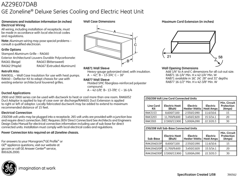
This manual suits for next models
6
Table of contents
Languages:
Other GE Air Conditioner manuals

GE
GE ASQ06LL Manual

GE
GE AJEM12DCD Original instructions

GE
GE Carry-Cool AT505 User manual

GE
GE AJCM08ACF Series Operating instructions

GE
GE AKQ06LZ Operating instructions

GE
GE ASR05LC Operating instructions

GE
GE ENERGY STAR AED08LN Manual

GE
GE AEL05LV Operating instructions

GE
GE AEE12DQ Original instructions

GE
GE ABN12 User manual

GE
GE AGM05 Operating instructions

GE
GE AJCM08ACEQ1 Original instructions

GE
GE AZ61H12DAD Manual

GE
GE AEE23DN Assembly instructions

GE
GE AEE07KP User manual

GE
GE AEH24DSL1 Operating instructions

GE
GE AJCM12DCD User manual

GE
GE AEH18DN Operating instructions

GE
GE ASH12AL Operating instructions

GE
GE AEE12DN Manual