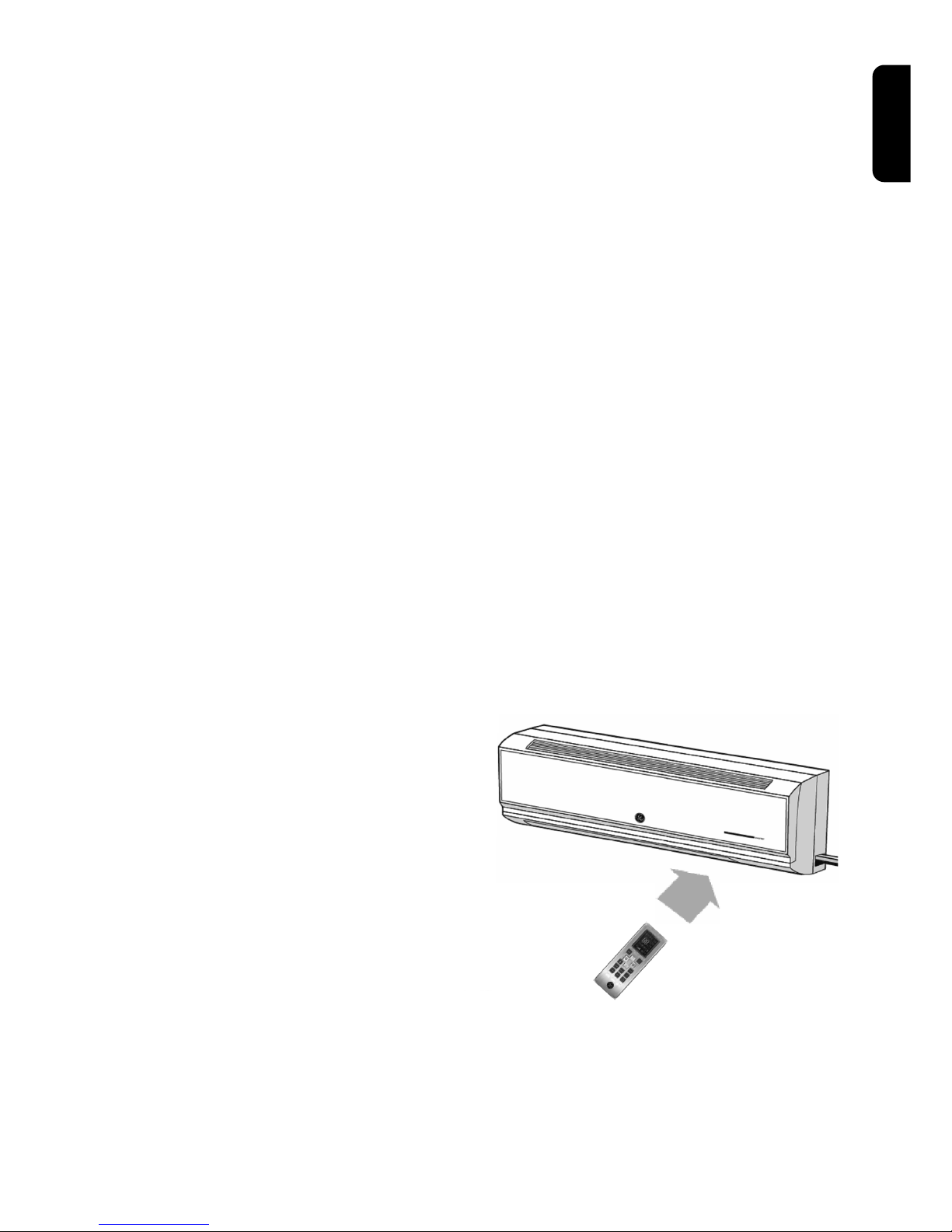
GE GE AIR Z09 IN EH Operating instructions

Wall Mounted
Split Air-Conditioner
Owner’s Manual and Installation Instructions
GE Consumer & Industrial
Appliances
GE imagination at work
English

Models covered in this document:
GE AIR Z09 IN EH GE AIR Z09 IN UH GE AIR Z09 EX NH
GE AIR Z12 IN EH GE AIR Z12 IN UH GE AIR Z12 EX NH
GE AIR Z17 IN NH GE AIR Z17 EX PH
GE AIR Z21 IN NH GE AIR Z21 EX PH

3
English
Contents
To get the full benefit from your new air-conditioner, please read this
Owner’s Manual carefully before operating the unit.
Thank you for choosing a GE air-conditioner.
Please keep this document for future consultation.
Owner’ s Manual 4
Important safety information 4
Name and function of parts 5
Remote control 6
How to operate your air-conditioner 8
How to insert batteries 10
User notices 10
Care and maintenance 10
Troubleshooting 12
Installation Instructions 13
Accessories and installation diagram 13
General installation instructions 15
Installing the indoor unit 16
Installing the outdoor unit 21
Test operation and after installation check 23
Technical specifications 24

4
• Make sure you push the power plug all
the way into the socket. Failure to do so
can cause an electric shock, overheating
or even a fire.
• Do not remove the power plug while the
machine is operating except in an
emergency.
•Never use an extension cord or splice the
power cord.
•Never share the same power outlet with
another electric appliance.
• Do not insert the power plug into the
outlet with wet hands.
• Never insert fingers or objects into the air
intake or outlet vents.
• Do not aim chilled or heated air directly
onto the body for long periods.
• Disconnect the power supply
immediately if you smell burning or
smoke and contact your service center.
• Do not attempt to repair the air-
conditioner yourself.
• Consult with a professional electrician to
ensure that adequate circuit breakers,
fuses and other safety devices are in
place.
•Disconnect the unit whenever it will be
out of service for extended periods.
•Always disconnect the power supply
before cleaning the machine.
• Never pull on the cord to remove the
power plug.
Important safety information
Read all instructions before use
• Do not place a space heater near the
air conditioner. Airflow from the air
conditioner can cause incomplete
combustion in a space heater, resulting
in dangerous fumes.
• Keep combustible sprays away from the
unit.
•Ensure that the unit is mounted securely.
• Do not place objects on the unit.
• Never block the air intake or outlet vents.
• The indoor unit should be installed
approximately 2,0 m from the ground.
• Extreme temperature differentials can be
harmful to health.
• Do not use the air-conditioner for drying
clothes, preserving foods or other
functions for which it was not designed.
• Splashing water on the unit may cause
an electric shock and malfunction.
• The ground (earthing wire) must be
properly connected. Do not connect the
earth wire to a gas or water pipe,
lightning rod or telephone earth lines.
Owner’s Manual
WARNING!
Use this appliance only for its intended purpose as described in this Owner’s Manual
When using electrical appliances, basic safety precautions should be taken, including the
following:

5
English
Name and function of parts
1. Front cover
2. Air filters
3. Key switch
4. Louver
5. Power plug1
6. Drain hose
7. Wireless remote controller
8. Connection pipe
9. Air outlet cover
Á
Â
Ã
Ä
Å
Æ
Ç
È
À
Air in
Air in
Air out
Air out
(1) GE AIR Z17 and GE AIR Z21 do not have a power plug on the indoor unit
as they are powered through the outdoor unit.

6
Remote control
Remote controller
General remarks
• Be sure there are no obstructions
between the receiver and the remote
control unit. The unit has a range of
approximately 8 meters.
• Do not expose the remote control unit to
moisture, excessive direct sunlight or heat.
• Do not drop or throw the remote
control unit.
• When restarting, the unit resumes
operating on the last mode set before
shut down. The outdoor unit will restart in
approximately 30 seconds.
1. ON/OFF button
Press this button to turn the unit on or off.
2. FAN button
Press this button to change fan speed. There are three
speeds to choose from, or set the FAN to AUTO to let the
unit control the air flow.
3. MODE button
Select the desired mode of operation by pressing this
button. The unit can operate on: COOL, DRY, FAN or
HEAT modes.
4. AUTO button
Press this button to enter AUTO mode operation. In
AUTO mode, the microcomputer automatically controls
the rate of cooling and heating of the room. Press once
more to return to the previous operating mode.
5. TEMP buttons
Press PLUS ( ) or MINUS ( ) button to set temperature
up or down. Temperature can be set from 16°C to 30°C
in COOL, DRY and HEAT modes.
COOL mode
DRY mode
FAN mode
HEAT mode
Á
Ã
À
Ä
Â

7
English
Remote controller
Å
Æ
Ç
È
É
11
12
6. JET button
In COOL or HEAT mode, press this button to let the
air-conditioner run at its full capacity. Change MODE
or fan speed to stop this operation.
Note: The air-conditioner runs at its
full capacity continuously under
this mode. Press MODE or FAN
button to go back to its previous
operating mode.
7. TIMER ON, OFF buttons
When the unit is in off status, press TIMER ON button to
turn it on at the specified time up to 24 hours in
advance. Press TEMP buttons and select TIMER ON
time. Then, press TIMER ON button once more to
confirm the time.
When the unit is operating, press TIMER OFF button to
turn it off at the specified time up to 24 hours in
advance.
8. SURROUND button
Press this button to let the air-conditioner control the
rate of cooling or heating with extra input on
surrounding room temperature from the remote
controller. Press this button once more to stop the
operation.
9. SLEEP button
Press to set the sleep function.
Press once more to stop the sleep function.
10. SWING button
Press to start louver moving automatically.
Press again to stop louver moving.
11. CLOCK button
Press to set the current time in the remote controller.
Adjust current time with TEMP buttons. Time changes
with 1 minute interval each time TEMP buttons are
pressed. Time changes with 10 minute interval when
TEMP buttons are pressed for 2 seconds or longer
12. LIGHT button
Press to turn off or on the LED display
on the indoor unit.

8
How to operate your
air-conditioner
• AUTO mode operation
In AUTO mode, the microcomputer
automatically controls the rate of cooling
and heating of the room. If the room
temperature is higher than 25ºC, the unit
will automatically switch to COOL mode.
If the room temperature is lower than
20ºC, the unit will automatically switch to
HEAT mode.
• FAN mode operation
Use the FAN mode to ventilate air in the
room without cooling, heating or drying
the air. Use the FAN button of the remote
controller to set the fan speed.
• TIMER ON operation
When the unit is in off status, press TIMER
ON button to turn it on at the specified
time up to 24 hours in advance. Adjust
time with TEMP buttons. Time changes
with 1 minute interval each time TEMP
buttons are pressed. Time changes with
10 minute interval when TEMP buttons
are pressed for 2 seconds or longer.
Press TIMER ON button again to confirm
the TIMER ON time.
•TIMER OFF operation
When the unit is in operation,
press TIMER OFF button to turn it off at
the specified time up to 24 hours in
advance. Adjust time with TEMP buttons.
Then, press TIMER OFF button again
to confirm the TIMER OFF time.
• COOL mode operation
The microcomputer automatically
controls the rate of cooling. It adjusts the
operation of the unit according to the
actual room temperature and the desired
temperature. If the room temperature is
higher than the desired temperature, the
unit will cool the air of the room. If the fan
speed is set at AUTO, the microcomputer
will control the speed of the indoor fan
according to the target temperature.
• HEAT mode operation
The microcomputer automatically
controls the rate of heating. It adjusts the
operation of the unit according to the
actual room temperature and the desired
temperature. If the room temperature is
lower than the desired temperature, the
unit will heat the air of the room. If the fan
speed is set at AUTO, the microcomputer
will control the speed of the indoor fan
according to the target temperature.
• DRY mode operation
Use the DRY mode to both cool the air
and reduce the moisture contained in the
air. The microcomputer automatically
adjusts the operation of the unit
according to the actual dryness and
temperature of the room, and according
to the desired temperature. If the room
temperature is higher than the target
temperature, the unit will both cool and
dry the air of the room. The fan goes to
low speed in DRY mode operation.

9
English
• SLEEP mode operation
When the unit is cooling or drying and
operating in SLEEP mode, the target
temperature will gradually increase by
1°C per hour for two hours.
When the unit is heating and operating in
SLEEP mode, the target temperature will
gradually decrease by 1°C per hour for
two hours.
• Auto-restart function
If the network loses power, and if the unit
was in operation when the power cut
occurred, it will automatically restart
when the network regains power.
• JET mode operation
In JET mode, the air-conditioner runs at
its full capacity to cool down or heat up
the room temperature quickly. Press JET
button during COOL or HEAT mode to
enter JET mode operation. Press JET
button or MODE button to go back to its
previous operating mode.
Note: The air-conditioner runs
at its full capacity continuously
in JET mode. Press JET
button once more or MODE
button to go back to the previous
operating mode.
• SURROUND mode operation
In SURROUND mode, the air-conditioner
controls the rate of cooling or heating
with extra input of surrounding room
temperature from the remote controller.
The remote controller senses and sends
the surrounding temperature to the air-
conditioner once every 10 minutes. Press
SURROUND button to activate
SURROUND mode. Press once more to
disable the SURROUND mode.
Note: The head of the remote controller
should face the air-conditioner so that
the SURROUND mode signal will be
reliably delivered to the air-conditioner.

10
How to insert batteries into the
remote control unit
• Slide the battery cover off from the back of
the remote control unit.
• Insert two AAA batteries.
• Slide the cover back in place.
NOTE:
• Do not mix new and used batteries or
rechargeable and non-rechargeable
batteries.
• Remove batteries from the remote control unit
when it is out of service for long periods.
• Fresh batteries can normally be expected
to last up to one year.
• Operate the remote control unit at least
1 meter or more away from a television or
audio device.
• Do not aim the air current directly at
animals or plants.
•Disconnect the power if the unit is out of
service for extended periods.
•Clean the air filter and maintain the air
cleaner on a regular basis.
• Remove batteries if the remote controller is
out of service for long periods.
• Avoid strong sunlight and draw curtains or
shades when cooling.
• Keep windows and doors shut to avoid the
loss of conditioned air.
•Select the most appropriate temperature to
save energy. Keep the room approximately
5°C cooler than the outside temperature
when operating in COOL mode.
• Adjust the direction of the airflow
appropriately. Remember that warm air
rises and cool air sinks, so adjust the louver
downward for heating and upward for
cooling to take advantage of natural
convection currents.
User notices
CAUTION
• Always turn power off and remove the
power plug before cleaning the unit.
• NEVER sprinkle water on either the
indoor or the outdoor unit to clean it.
• Wipe the indoor and outdoor units with
a clean, soft dry cloth or a cloth slightly
moistened with water or cleaner.
• Before starting the unit, be sure that
nothing obstructs the air outlet and the
intake vents.
Care and maintenanceHow to insert batteries
Cleaning the outdoor unit
1. Regularly clean dust from outdoor unit.
2. Repaint any rust colored areas on the
outdoor unit.
Cleaning the indoor front cover
1. Pull in the direction indicated by the
arrows to open the front cover.
2. Wipe with a cloth slightly moistened with
water or cleaner and then dry in the
shade. Do not use water above 45°C to
wash the panel. It could cause
deformation or discoloration.
3. Close the front cover.

11
English
Cleaning the indoor air filters
(It is recommended that the air filters be
cleaned once every three weeks.)
1. Open the front cover, take hold of the air
filter tab, raise it slightly, and then remove
it.
2. Vacuum dust from the filters or wash
them with water and dry them in the
shade.
Note: Do not use water above 45°C to
wash the filters. It may cause
deformation or discoloration.
3. Reinstall the filters with the side marked
‘front’ facing forward. Close the front
cover.

12
Troubleshooting
If a malfunction occurs, check the following
before contacting your service center.
Problem
Indoor unit does not start immediately
when the air-conditioner is switched on
An unusual smell coming from the outlet
after the unit begins operating
A sound like water flowing can be heard
during operation
Mist is emitted during cooling mode
Creaking noise can be heard when the unit
starts or stops
The air conditioner does not operate at all
Cooling or heating efficiency is not good
The wireless remote controller does not
function
Troubleshooting
Once the air-conditioner is stopped, it will
not operate for approximately three
minutes while the refrigerant settles down.
This is usually temporary and caused by
odors concentrated in the air intake going
into the air conditioner. If it continues, turn
power off and contact your service center.
This is a normal sound caused by the
refrigerant flowing inside the unit.
This is normal. The conditioned air cools
down the room air rapidly and it sometimes
looks like fog.
This is a temporary phenomenon caused by
the deformation of plastic due to the
change in temperature. If it continues,
contact your service center.
Please check for the following:
1. Is a power connection loose?
2. Is the circuit breaker activated?
3. Is the voltage higher than 253 volts or
lower than 198 volts?
4. Is TIMER ON in operation?
1. Is the set temperature suitable?
2. Is the air inlet or outlet obstructed?
3. Are the air filters dirty or clogged?
4. Is the indoor fan speed set too low?
5. Is there another heat source in the room?
1. Is the remote controller unit out of range
(more than 8 meters from unit)?
2. Replace worn out batteries.
3. Are there any obstructions between the
wireless remote controller and the signal
receiver?

13
English
Installation Instructions
Accessories and
installation diagrams
Use only the accessories listed below for the
installation. Failure to do so may lead to gas
leakage, electric shock, a fire hazard or other
possible safety hazards.
Check all parts listed below are present
before proceeding with the installation.
Part GE AIR Z09 GE AIR Z17 GE AIR Z21
GE AIR Z12
Rear panel 1 1 1
Remote controller 1 1 1
Battery (AAA type) 2 2 2
Tapping screw 555
Thermal insulation hose 1 1 1
Outdoor drain elbow 1 1 1
Copper pipe, Liquid 1 (1/4”) 1 (1/4”) 1 (3/8”)
Gas 1 (1/2”) 1 (1/2”) 1 (5/8”)
Square ring 1 1 1
Cable, main power 1 (attached to indoor) 1 (3x2.5mm*2) 1 (3x2.5mm*2)
Cable, between indoor 1 (4x1.5mm*2) 1 (4x2.5mm*2) 1 (4x2.5mm*2)
and outdoor
Immediately stop all operations, disconnect
the power and contact your nearest service
center in the event any of the following
happens:
• Unusual noise while the unit is operating
• Power fuse or breaker switch repeatedly
activates
• Water or fluid splashes into the unit
• Electrical wirings and power plug become
very hot
• An unpleasant smell is emitted during
operation

14

15
English
General installation
instructions
IMPORTANT NOTES
• The installation must be carried out by
trained and qualified service personnel
according to the instructions contained
in this manual.
• Contact your service center before
beginning installation to avoid possible
malfunctions.
• When picking up and moving the unit,
be guided by trained and qualified
personnel.
• The ground connection of the air-
conditioner must be made correctly and
securely to the recommended earth
ground points. Contact the service
center if you have any question.
• Installation in the following places may
cause malfunction:
- Any place where machine oil is used.
- Any site with a lot of salinity.
- Any site with sulfured gas such as
hot springs.
- Any site subject to high-frequency
waves such as places close to radio
equipment, welders and medical
equipment.
- Any place under strong
electromagnetic fields or in a
chemical environment.
• If the air-conditioner has to be installed
on such a site, contact your service
center for advice.

16
Installing the indoor unit
Choose installation location
1. The height of installation should be 2
to 3 meters from the floor.
2. The air inlet and outlet of the indoor unit
should not be covered or blocked in any
way so that the conditioned air can reach
all parts of the room.
3. Select a location which enables easy
connection with the outdoor unit. Take
into consideration the maximum allowed
length and height of piping. This data is
provided in the installation data at the
end of this manual.
4. Select a location where accumulated
condensation can be drained
conveniently.
5. Avoid locations near a heat source, high
humidity or an inflammable gas.
6. Select a location strong enough to
withstand the full weight and vibration of
the unit.
7. The location should conform to the
installation dimension diagram.
8. Be sure to leave enough space to allow
access for routine maintenance.
9. Install at least 1 meter away from other
electric appliances such as television,
audio device, etc.
10.Choose a location where it is easy to
remove and clean the filter.
11.Do not install the unit in the immediate
vicinity of a laundry, bath, shower or
swimming pool.
12.The power plug must be accessible after
the appliance is correctly positioned.
Install the rear panel
1. Always mount the rear panel horizontally.
2. Fix the rear panel on the selected location
with the screws supplied with the unit.
3. Be sure the rear panel is firmly fixed.
The mounting must be able to withstand
a weight of at least 60 kilograms.
The weight should be evenly shared by
each screw.
Electrical wiring
To connect the connecting cable, refer to
table 1 and table 2 below to identify the
required electrical wiring for your air-
conditioner and follow these instructions.
1. Lift the indoor unit front cover.
2. Remove the lid for terminal block located
on the right of the unit.
3. Route the connecting cable from the back
of the indoor unit and pull it toward the
front through the wiring hole for
connection.
4. Connect the wires strictly based on the
correspondence between the wire colors
and the terminal block codes as
described in table 2.
5. Hold the connecting cable with the wire
clamp. Then, re-assemble the lid of
terminal block back to the front cover. For
GE AIR Z09 and GE AIR Z12, the lid of
terminal block acts as the wire clamp and
cable is fixed when the lid is re-
assembled to the front cover.
6. Re-assemble the front cover.

17
English
Model
GE AIR Z09
GE AIR Z12
GE AIR Z17
GE AIR Z21
Cable between indoor and
outdoor units
1 for power and signal
(terminal block)
1 for power and signal
(terminal block)
Main power cable
on indoor unit
with plug (connected)
on outdoor unit
without plug
Table 1 Cables to be connected to indoor and outdoor units
Model
GE AIR Z09
GE AIR Z12
Indoor unit
terminal block
N(1)
2
3
ground
Connecting cable
blue
black
brown
yellow / green
Outdoor unit
terminal block
N(1)
2
3
ground (on chassis)
Table 2 Cable connection between indoor and outdoor units
Model
GE AIR Z19
GE AIR Z21
Indoor unit
terminal block
N(1)
2
3
ground
Connecting cable
blue
black
brown
yellow / green
Outdoor unit
terminal block
N(1)
2
3
ground (on chassis)

18
Model
GE AIR Z17
GE AIR Z21
Line voltage
Neutral
Live
ground
Main power cable
blue
brown
yellow / green
Outdoor unit
terminal block
N(4)
5
ground (on chassis)
Table 3 Connection of main power cable

19
English
NOTES:
1. All electrical work must be performed
by qualified personnel according to
local regulations and this manual.
2. The exclusive power line with rated
voltage must be used.
3. Circuit breaker must be installed
between the air-conditioner and the
power line.
4. Make sure the specified circuit breaker
is used.
5. If the power supply cord of the unit is
damaged, it must be replaced with a
special cord available from the
manufacturer or its service agent.
6. The diameter of the power connecting
cable must be equal to or exceed the
specified value to operate the air-
conditioner safely.
7. Wiring work must conform to national
standards.

20
Install the piping hole
1. Make the piping hole Ø80 mm in the wall
at a slight downwards slant.
2. Insert the piping hole sleeve into the hole
to prevent the connection piping and
wiring from being damaged while passing
through the hole.
Install the connection pipes
1. When routing the piping and wiring from
the left or right side of the indoor unit,
cut out the tailings from the chassis if
necessary (shown in Fig. 1). Cut out
tailing 1 when routing wiring only.
Cut out tailing 2 when routing both
the wiring and piping.
2. Connect the pipes with the appropriate
union pipes on the indoor unit.
3. Cover piping joints with pipe cover.
4. Insulate piping with thermal insulation
hose provided with the unit.
NOTE:
1. The connection pipes should be
connected to the indoor unit first and
the outdoor unit second.
2. Be careful when bending the connection
pipes so as not to damage them.
3. Do not bend a connection pipe more
than three times in the same location.
4. Make sure the maximum length and
height falls within the limits provided in
the installation data at the end of this
manual.
5. Leakage will occur if the torque is too
great when tightening the flare nuts.
Refer to table 4 on page 21 to identify
the appropriate torque.
Install the drain hose
1. Place the drain hose at a downward slant
for optimal drainage.
2. Do not wrench or bend the drain hose or
flood the end with water.
Last steps for installing the indoor unit
1. Wrap the piping and wiring and pull them
through the cut out tailing hole as shown
in Fig. 2.
2. Lift the surface panel of the indoor unit
and install the air cleaners.
3. Pull the piping through the connection
pipe hole and hang the two mounting
slots of the indoor unit on the proper tabs
of the rear panel and check that it is
mounted strong enough.
Fig. 2
Connection
cord
Connection
pipes
Wrapping
tape
Drain
hose
Fig. 1
Tailing 3 Tailing 2
Tailing 1
This manual suits for next models
9
Table of contents
Other GE Air Conditioner manuals

GE
GE AEC08 User manual

GE
GE AZ28E12DAB Manual

GE
GE AEH12 Series Operating instructions

GE
GE CLIMATISEUR AEH18* Operating instructions

GE
GE AGR05 Operating instructions

GE
GE AGW10 Operating instructions

GE
GE AVV1O Training manual

GE
GE Thinline AJH06 Installation instructions

GE
GE AGM06LJ Operating instructions

GE
GE AX918D Installation instructions

GE
GE ASQ08FK Manual

GE
GE AJES12DCC User manual

GE
GE AEM24DX Operating instructions

GE
GE Appliances AKQ24DNT1 Original instructions

GE
GE AHEL06BB User manual

GE
GE ASM08LL User manual

GE
GE AGE12 Operating instructions

GE
GE APE07 User manual

GE
GE AZ45E07EA Series How to use

GE
GE Appliances Zoneline 2800 Operating instructions