GE Quadcore HD User manual

Questions? Contact our U.S.-based
Consumer Care at 1-800-654-8483
between 7AM-8PM, M-F, Central Time.
See reverse for easy-to-follow instructions
and exclusive deals.
Please call before
returning to store
CALL
Quadcore HD
Antenna
User Manual

2
WARNING: INSTALLATION OF
THIS PRODUCT NEAR POWER
LINES IS DANGEROUS. FOR
YOUR SAFETY, FOLLOW THE
INSTALLATION DIRECTIONS.
WATCH FOR WIRES! YOU CAN
BE KILLED IF THIS ANTENNA
COMES NEAR ELECTRIC POWER
LINES. READ INSTRUCTIONS!
Instructions made easy

3
TABLE OF CONTENTS
IMPORTANT SAFETY INSTRUCTIONS ....................................................4
SELECT AND MEASURE YOUR INSTALLATION SITE.........................5
PARTS LIST........................................................................................................6
ASSEMBLING THE ANTENNA....................................................................8
ANTENNA GROUNDING & CONNECTION........................................11
ANTENNA REMOVAL .................................................................................14
ANTENNA HELPFUL TIPS.........................................................................15
Instructions made easy
Read instructions or watch easy-to-follow
video. Scan code or visit byjasco.com/48896i

4
IMPORTANT SAFETY INSTRUCTIONS:
• NEVER touch ANYTHING or ANYONE in contact with a
power line. You can be electrocuted. In case of an accident
or emergency, call 911 immediately for help.
• INSPECT your installation site carefully for power lines.
Make sure there is no possibility the antenna, its mounting
structure or your ladder can contact power lines. Consider
what can go wrong during installation.
• KEEP the distance between power lines and the antenna
and its mounting structure at least twice the combined
height of the antenna and mounting structure added
together. In the event the antenna falls during or after
assembly, there must be sufficient distance to ensure it
does not contact the power lines.
• KEEP your ladder, the antenna and antenna mounting
structure (such as mast, pole and mount) far away from
power lines at all times.
• GROUND the antenna and the antenna mounting
structure in accordance with the NEC electrical code, all
state and local electrical code requirements.
• COMPLETE the antenna assembly on the ground.
• DO NOT use a metal ladder or install the antenna on a
windy day. If the antenna or mast starts to fall, do not
attempt to catch the antenna.
• EXERCISE caution when working on a roof.
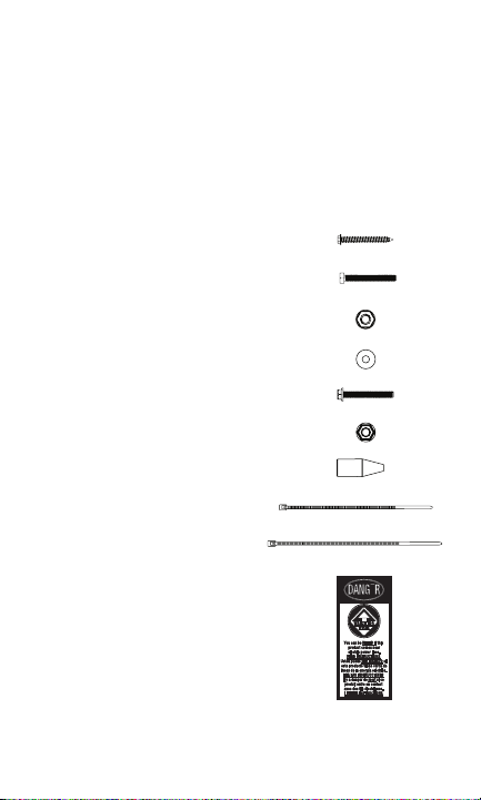
• APPLY the included danger label to the base of the
antenna mounting structure.
• INFORM others of the danger of touching power lines or
touching other objects in contact with power lines.
• CONTACT a professional installer to install the
antenna if you are unsure how to safely install and
ground this antenna.
• DO NOT use the power inserter and power supply
outdoors. They are rated for indoor use only. Use only the
power supply provided with the antenna.

5
SELECT AND MEASURE YOUR INSTALLATION SITE
When selecting the antenna installation site:
1. Choose a SAFE location far away from power lines. Keep
the distance between power lines and the antenna and its
mounting structure at least 2 times the combined height
of the antenna and its mounting structure. Refer to the
Important Safety Instructions.
2. Determine the location of the broadcast towers in your
area so you can face the antenna elements toward those
towers. Online resources, such as www.antennaweb.org
and www.dtv.gov can help identify the location of
broadcast towers in your area and the channels you can
expect to receive.
3. Check your local city and state building and electrical
codes. Make sure your planned installation is safe and in
compliance with all applicable codes, rules and regulations.
IF YOU ARE UNSURE OR DO NOT FEEL
CAPABLE OF INSTALLING THIS ANTENNA,
CONTACT A PROFESSIONAL INSTALLER.

6
Thank you for purchasing the GE branded Outdoor
Quadcore HD Antenna. This sturdy, high-performance
antenna is designed to receive UHF and VHF broadcast
signals. Its compact design allows you to install it almost
anywhere on your home’s exterior.
PARTS LIST:
1. Antenna elements (x2)
2. Main housing unit (x1)
3. M5 X 50mm bolts (x4)
4. VHF dipoles (x2)
5. M3 X 8mm bolts (x4)
6. M5 X 12mm bolts (x2)
7. Backplate (x1)
8. U-bolt and clamp assembly (x1)
a. Clamp (x1)
b. U-bolt (x1)
c. Wing nuts (x2)
9. Mounting bracket (x1)
10. J-mount (15/16in. or 2/5cm) (x1)

7
PARTS LIST (CONT.):
11. 2in. X 50.8mm lag screws (x4)
12. M6 X 50mm bolts (x2)
13. M6 locking nuts (x2)
14. M6 washers (x4)
15. M5 X 40mm bolts (x1)
16. M5 nut (x1)
17. Rubber boot (x1)
18. Small zip tie (x1)
19. Large zip tie (x2)
20. Danger label (x1)

8
ASSEMBLING THE ANTENNA:
1. Connecting the Antenna Elements to the
Main Housing Unit
a. Connect each antenna element to the main housing
unit by inserting the housing unit’s round protrusions
into the round groove on each antenna element
(Fig. 1a, Fig. 1b & Fig. 1c).
b. Secure with the M5 X 50mm bolts (Fig. 1d & Fig. 1e).
c. After installation (Fig. 1f & Fig. 1g).
(Fig. 1a)
(Fig. 1b)
(Fig. 1c)
(Fig. 1d) (Fig. 1e)
(Fig. 1f front) (Fig. 1g back)

9
2. Connecting the VHF Dipoles
Place the VHF dipoles in the matching grooves on the
back of the main housing unit, making sure the side of
each dipole marked “THIS SIDE UP” is facing upward.
Secure the dipoles with M3 X 8mm bolts (Fig. 2a & Fig. 2b).
3. Attaching the U-bolt and Clamp Assembly to
the Main Housing Unit
Place the middle of the U-bolt in the groove of the metal
backplate and align the holes on the backplate with the
holes on the main housing unit. Secure the U-bolt in place
with M5 X 12mm bolts (Fig. 3a & Fig. 3b).
(Fig. 2a)
(Fig. 2b)
(Fig. 3a) (Fig. 3b)

10
4. Installing the Assembled Antenna
a. Locate a position on the house that is far away from
power lines. Refer to the Important Safety Instructions.
b. Secure the mounting bracket to the location selected
or the antenna. The 2in. X 50.8mm lag screws have
been provided for some installations.
c. Connect the J-mount to the mounting bracket
(Fig. 4a) using the M6 X 50mm bolts, M6 locking nuts
and M6 washers.
d. Position the J-mount perpendicular to the ground using
a small level.
e. Slide the antenna onto the J-mount (Fig. 4b). Face the
antenna elements toward the broadcast towers in your
area. Tighten the wing nuts on the U-bolt when the
antenna is in the desired position.
f. Apply the provided DANGER label to the base of the
mounting structure in a clearly visible location if your
antenna mounting structure, such as a mast, J-mount
or pole, does not already have one.
(Fig. 4a)
(Fig. 4b)

11
ANTENNA GROUNDING & CONNECTION
The National Electric Code (NEC) requires your outdoor antenna
installation to be properly grounded. This involves grounding
the antenna and the antenna mounting structure. This helps
protect you and your property in the event of static buildup on
the antenna or lightning near your home.
NOTE: If you had a satellite or cable system installed at your
home, you may be able to use some parts from this system for
your antenna installation.
1. Ground the Antenna Mount: Attach a #8 aluminum or a
#10 copper grounding wire to the antenna mounting
structure, such as a pole, mast, tower, etc. In some cases,
a bolt on the mount can be used for making this
connection. When using the provided J-mount, use the M5
bolt and M5 nut in the hole on the J-mount located above
the mounting bracket to make this connection (Fig. 5a).
Tighten this connection securely. Ensure there is a good
electrical connection between your mounting structureand
grounding wire. Run the grounding wire as straight as
possible and use standoff insulators spaced four (4) to
six (6) feet apart. Attach the grounding wire to an
acceptable building ground location. See Grounding Block
How-To for a list of acceptable building ground locations.
(Fig. 5a)

12
2. Connect the Antenna: Use an outdoor-rated coax cable
to connect the antenna to the 75-ohm grounding block
(not provided). Fig. 5b is an example of a 75-ohm
grounding block. Verify that the grounding block is properly
grounded. See Grounding Block How-To.
If you make your own coax cable, slide the rubber boot
over the cable before you place the connectors on the
cable. Once you have attached the cable to the antenna,
slide the rubber boot into the round channel on the main
housing unit.
If you are using a pre-built cable with connectors,
follow these steps.
a. Cut four slits spaced evenly apart at the narrow tip of
the provided rubber boot, approximately 1/4in.
in length (Fig. 5c).
b. Run the coax cable through the narrow end of the
rubber boot and attach the cable to the antenna.
c. Slide the rubber boot into the round channel on the
main housing unit.
d. Wrap the small zip tie around the slits in the narrow
end of the rubber boot and pull it tight.
From the grounding block, connect an in-wall rated
coax cable that will run through the wall into your home
to an interior cable wallplate connection or, for whole-
home installation, a coaxial splitter in your attic. A separate
(Fig. 5b)
(Fig. 5c)

13
in-wall rated coax cable running to a separate cable
wallplate is required for each location served by the splitter.
The 75-ohm grounding block needs to be placed as close
as possible to the point where the second coax cable
enters your home.
NOTE: Be sure to leave enough slack in the coax cable to
create a drip loop so moisture cannot enter your house.
You will also need to seal the coax cable entry point into
your house with an exterior caulk.
NOTE: Use of multiple splitters in a whole-home
installation will seriously degrade signal quality and is
not recommended.
3. Connect your TV’s antenna port to the coax wallplate
using coaxial cable.
4. Follow your HDTV’s instruction manual to scan for
channels on your TV.
Grounding Block How-To:
Your existing outdoor antenna should already have a properly
installed grounding block in place, but if it must be moved
or is improperly grounded, please follow these important
instructions to ensure your antenna is safely grounded.
1. Connect a #8 aluminum or #10 grounding wire to a
screw terminal on the 75-OHM grounding block.
2. Connect the other end of the wire to an acceptable
building ground location. See examples below.
Examples of acceptable building grounding locations are:
• The building or structure grounding electrode system as
covered in 250.50 in the NEC
• Grounded interior metal water piping system within 5ft.
from its point of entrance to the building
• Grounded, non-flexible metallic power service raceway
• Service equipment enclosure, the grounding electrode

14
conductor or the grounding electrode conductor metal
enclosure of the power service
• An 8ft. grounding rod driven into the ground can be
used as long as it is connected to the central building
ground by a #6 or heavier bonding wire.
Refer to the NEC sections 250 and 810 for other acceptable
grounding methods.
Double-check all your connections after installation is
complete. Ensure there are good electrical connections of your
grounding wires and coax cables. See Fig. 5d for an example of
a properly grounded antenna installation.
IF YOU ARE UNSURE HOW TO PROPERLY GROUND YOUR
ANTENNA INSTALLATION, CONTACT A PROFESSIONAL
INSTALLER IN YOUR AREA.
ANTENNA REMOVAL
Inspect the area carefully for power lines. Look for any new
power lines that may have been installed. Make sure there is no
possibility the antenna, its mounting structure or your ladder
can contact power lines. Consider what can go wrong during
the antenna removal. Repeat the steps for antenna installation
in reverse order.
(Fig. 5d)
-

48896 V1 6/20
MADE IN CHINA
GE is a trademark of General Electric Company and is
under license by Jasco Products Company LLC, 10 E.
Memorial Rd., Oklahoma City, OK 73114.
This Jasco product comes with a limited-lifetime
warranty. Visit www.byjasco.com for warranty details.
Questions? Contact our U.S.-based Consumer Care at
1-800-654-8483 between 7AM -8PM Central Time.
ANTENNA HELPFUL TIPS
Maximize the number of channels by testing the antenna in several
locations. Be sure to run a TV channel scan in each position. Refer to
your TV’s instruction manual if necessary.
For best performance, position or mount the antenna as high as
possible facing the broadcast towers.
Visit www.antennaweb.org or www.dtv.gov to determine the available
television stations and broadcast tower locations in your area.
QUESTIONS? ISSUES?
CALL OUR U.S.-BASED EXPERTS AT
1-800-654-8483

¿Tiene preguntas? Póngase en contacto con
nuestro servicio de atención al consumidor de
EE. UU. al 1-800-654-8483, de lunes a viernes,
de 7 a. m. a 8 p. m. (hora estándar del centro).
Antena
Quadcore HD
DEBE REALIZAR UNA BÚSQUE-
DA DE CANALES DESPUÉS
DE LA INSTALACIÓN.
CONSULTE EL MANUAL
DE SU TELEVISOR PARA
VER LAS INSTRUCCIONES
DE BÚSQUEDA O LLAME AL
FABRICANTE DEL TELEVISOR.
BUSQUE
CANALES
Llámenos antes
de volver a la tienda
LLAME

17
ADVERTENCIA: LA INSTALACIÓN
DE ESTE PRODUCTO CERCA
DEL TENDIDO ELÉCTRICO ES
PELIGROSA. POR SU SEGURIDAD,
SIGA TODAS LAS INSTRUCCIONES
DE INSTALACIÓN.
¡TENGA CUIDADO CON LOS
CABLES! PUEDE MORIR SI ESTA
ANTENA ESTÁ CERCA DE LÍNEAS
DEL TENDIDO ELÉCTRICO. ¡LEA
LAS INSTRUCCIONES!
PELIGRO

18
ÍNDICE
INSTRUCCIONES IMPORTANTES DE SEGURIDAD.............................19
SELECCIONE Y MIDA EL LUGAR DE LA INSTALACIÓN....................20
LISTA DE PIEZAS................................................................................................21
ENSAMBLAJE DE LA ANTENA....................................................................23
CONEXIÓN Y PUESTA A TIERRA DE LA ANTENA................................24
RETIRO DE LA ANTENA..................................................................................29
CONSEJOS ÚTILES SOBRE LA ANTENA.................................................30

19
INSTRUCCIONES IMPORTANTES DE SEGURIDAD:
• NUNCA toque cualquier OBJETO o PERSONA en contacto
con una línea eléctrica. Puede electrocutarse. En caso de
un accidente o una emergencia, llame inmediatamente
al 911 para pedir ayuda.
• INSPECCIONE detenidamente el lugar de la instalación en
relación con líneas eléctricas. Asegúrese de que no existe
la posibilidad de que la antena, la estructura de montaje
o su escalera puedan tener contacto con líneas eléctricas.
Tenga en cuenta lo que puede salir mal durante la instalación.
• MANTENGA la distancia entre las líneas eléctricas y la antena
y su estructura de montaje de un mínimo del doble de la
suma de la altura combinada de la antena y la estructura de
montaje. En caso de que la antena se caiga durante o después
del montaje, debe haber suficiente distancia para asegurarse
de que no tenga contacto con las líneas eléctricas.
• MANTENGA su escalera, la antena y la estructura de montaje
de la antena (como el mástil, poste y soporte) lejos de las líneas
eléctricas en todo momento.
• CONECTE A TIERRA la antena y la estructura de montaje
de la antena de acuerdo con el código eléctrico NEC, y todos
los requisitos de los códigos eléctricos estatales y locales.
• COMPLETE el montaje de la antena en el suelo.
• NO use una escalera de metal ni instale la antena en un
día ventoso. Si la antena o el mástil comienzan a caerse,
no intente sujetar la antena.
• ACTÚE con prudencia cuando trabaje sobre el techo.
• PEGUE la etiqueta de peligro incluida en la base de la
estructura de montaje de la antena.
• INFORME a las demás personas del peligro de tocar las
líneas eléctricas o tocar otros objetos en contacto con líneas
eléctricas.
• PÓNGASE EN CONTACTO con un instalador profesional para
instalar la antena si no está seguro de cómo instalar esta
antena y conectarla a tierra de forma segura.
• NO use el insertador de potencia y la fuente de alimentación
en exteriores. Están clasificados para uso exclusivo en interiores.
Use únicamente la fuente de alimentación suministrada con

20
SELECCIONE Y MIDA EL LUGAR DE LA INSTALACIÓN
Cuando seleccione el lugar de instalación de la antena:
1. Elija un lugar SEGURO lejos de líneas eléctricas. Mantenga la
distancia entre las líneas eléctricas y la antena y su estructura
de montaje de un mínimo de dos veces la altura combinada de
la antena y la estructura de montaje. Consulte las Instrucciones
importantes de seguridad.
2. Determine la ubicación de las torres de transmisión en su
área para ubicar los elementos de la antena de modo
que estén orientados hacia las torres. Recursos en línea,
como www.antennaweb.org y www.dtv.gov pueden ayudar
a identificar la ubicación de las torres de transmisión en su
área y los canales que puede esperar recibir.
3. Revise los códigos eléctricos y de construcción de su ciudad
y su estado. Asegúrese de que su instalación planificada es
segura y cumple con todos los códigos, normas y reglamentos
aplicables.
SI NO ESTÁ SEGURO O NO SE SIENTE
CAPAZ DE INSTALAR ESTA ANTENA,
PÓNGASE EN CONTACTO CON UN
INSTALADOR PROFESIONAL.
Table of contents
Languages:
Other GE Antenna manuals
Popular Antenna manuals by other brands

HUSTLER
HUSTLER 6-BTV installation instructions

Ubiquiti
Ubiquiti AirMax AMY-9M16 Quck Start Gude

Raymarine
Raymarine STV60 Installation & operation instructions

COBHAM
COBHAM SAILOR 1000 XTR Ku 8W Field Replacement Procedure

Proxim
Proxim Antenna Tsunami MP.11 specification

COBHAM
COBHAM HGA-6000 installation manual

axing
axing basic-line SAA 80-0 Series Operation instructions

Directive Systems & Engineering
Directive Systems & Engineering DSE1376LY manual

Channel Master
Channel Master 4220MHD instruction sheet

Ubiquiti
Ubiquiti PS-5AC quick start guide

Digital Video Broadcasting
Digital Video Broadcasting TRAVELSAT 68 LED Installation and use manual

Carbest
Carbest SNIPE user manual