manuals.online logo
Brands
  1. Home
  2. •
  3. Brands
  4. •
  5. Komunica
  6. •
  7. Antenna
  8. •
  9. Komunica HF-PRO-2-PLUS-T User manual

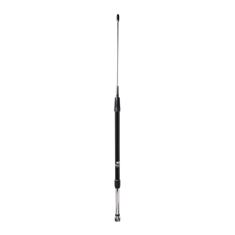
Komunica HF-PRO-2-PLUS-T User manual

HF/VHF
Telescopic Multi
Wide
B
and Antenna
H
F
-
P
RO
-
2-PLUS-T
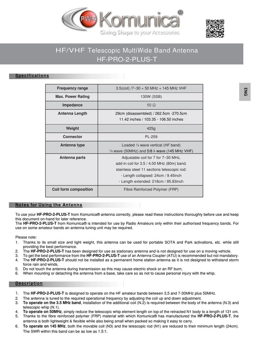
Specifications
Frequency range
3.5 MHz (coil) /7~30 + 40 + 50 MHz + 70 +145 MHz (VHF)
Max. Power Rating
130W (SSB)
Impedance
50 Ω
Antenna Length
29cm (disassembled) / 262.5cm -270.5cm
11.42 inches / 103.35 - 106.50 inches
Weight
425g
Connector
PL-259
Antenna type
Loaded 1/4λvertical (HF band)
1/4λ(40 & 50MHz) & 5/8λ(70 & 145 MHz VHF)
Antenna parts
Adjustable coil for 7 for 7~30 MHz,
add-in coil for 3.5 / 4.00 MHz (80m) band.
stainless steel 12 sections telescopic rod:
- Length collapsed: 24cm / 9.45inch
- Length extended: 218cm / 85.83inch
Coil form composition
Fibre Reinforced Polymer (FRP)
Notes fo
r
Using the Antenna
To use your HF-PRO-2-PLUS-T from Komunica® antenna correctly, please read these instructions thoroughly before use and keep
this document on-hand for later reference.
The HF-PRO-2-PLUS-T from Komunica® is intended for use by Radio Amateurs only within their authorized frequency bands. For
use on some amateur bands an antenna tuning unit may be required.
Please note:
1. Thanks to its small size and light weight, this antenna can be used for portable SOTA and Park activations, etc. while still
providing the best performance.
2. The HF-PRO-2-PLUS-T has been designed for use as stationary antenna and is not designed for use on a moving vehicle.
3. To get the best performance from the HF-PRO-2-PLUS-T use of an Antenna Coupler (ATU) is recommended but not mandatory
.
4. The HF-PRO-2-PLUS-T should not be installed as a permanent home station antenna as it is not designed to withstand storm
force rain and winds.
5. Do not touch the antenna during transmission as this may cause electric shock or an RF burn.
6. When mounting or detaching the antenna from a base, take care so as not to cause personal injury with the whip.
Desc
r
iption
1. The HF-PRO-2-PLUS-T is designed to operate on the HF amateur bands between 3,5 and 7-30MHz plus 50MHz.
2. The antenna is tuned to the required operational frequency by adjusting the coil up and down adjustment.
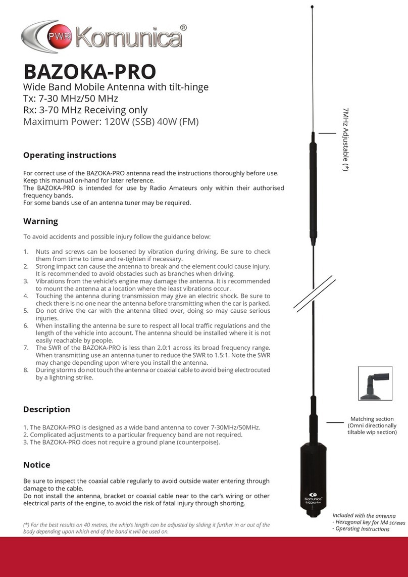
3. To operate on the 3.5 MHz band, installation of the additional coil (N.2) is required between the body of the antenna (N.3) and
telescopic whip (N.1) fully extended.
4. To operate on 50MHz, simply reduce the telescopic whip element length on top of the retracted N1 body to a length of 131 cm.
5. To operate on VHF 145 MHz, both the movable coil (N3) and the telescopic rod (N1) are reduced to their minimum length
(24cm). The SWR within this band can be as low as 1.5:1.
6. Thanks to the fiber reinforced polymer (FRP) material with which Komunica® has manufactured the HF-PRO-2-PLUS-T, the
antenna is both lightweight & flexible while also being small when packed so making it easy to carry.
ENG
This chart is indicative and refers to a
standard adjustment scale that may change
depending on each site and installation
method. It offers only indicative
measurements.
To make the fine tuning
try playing with the length of your scale and
the telescopic rod sections.
To operate at 50MHz, always have element
N3 retracted, and the telescopic rod (N1)
adjusted to a length of 131cm (about -4 of the
upper sections of the telescopic section
extended).
Frequency
(MHz)
Sections
extended
8m*
40
10
6m
50
7
*8m only for Latvia, Slovenia and Ireland
All values approximate and depend upon the
antenna’s surroundings
Frequency
(MHz)
Sections
extended
4m*
70
12
2m
144
5
*4 meters not available in all countries.
All values approximate and depend upon the
antenna’s surroundings
Errorsand omissions excepted(E &OE)
TRIPLE-MAG
Magnetic base
with triple magnet
maximum adherence
3pcs x 9cm
Connector: SO-239
Cable RG-58 (5mts)
HF-MAG
7 ~ 50MHz Magnetic
Ground Plane
Attachment
TRIPOD-KIT
Telescopic Tripod
Extendable 5 sec.
VHF: To operate element N3 must be
retracted & the telescopic rod N1
adjusted to the required length to form
either a 1/4λor 5/8λantenna. An SWR
in the range of 2-2.5:1 should be
expected.
Don’t forget to count the base section
of the telescopic whip!
Adjustment
1. When using on a static vehicle: Connect
your Komunica® HF-PRO-2-PLUS-T to a
stable magnetic base of a suitable diameter
(recommended Model: Komunica® TRIPLE-
MAG) or use a solid PL-259 mount, connected
securely. Pre-assemble the antenna and
adjust its length with reference to the coil
settings graph (1.1).
2. To be able to adjust to the required length
loosen the locking nut by hand.
3. To select the required frequency band, set
the position of the antenna body N3 over the
scale N4 to coincide with the value shown in
the chart (1.1).
4. Lightly tighten the locking ring by hand.
Never use tools such as pliers, as these could
damage your Komunica ® HF-PRO-2-PLUS-T
5. For fine tuning on HF, always perform your
TX tests with the lowest RF power possible.
Move the coil up or down until you have fine-
tuned to the desired frequency which is
indicated by lowest SWR.
7. Once the tuning is correct, you can already
increase the power, up to respecting the
maximum power of 130W-SSB. Should SWR
level be higher than 2:1 in use on HF please
check your ground plane or change the
location of your antenna on the car. Use an
Antenna Tuner for maximum flexibility.
Note
Should the SWR level be higher than 1.5:1 in
use on HF, please check your ground plane
or change the location of your antenna on the
car.
Use an Antenna Tuner for maximum
flexibility.
Recommendation
All antennas can have their effectiveness
reduced due to the bad radio propagation
conditions.
The HF-PRO-2-PLUS-T has been
manufactured under strict quality controls, if
damage is caused during shipping, please
contact your dealer promptly.
Design and specifications of this antenna
can be changed at any time without previous
notice.
Coil positioning chart (1.1)
Installation
1. When using PL-259 antenna mount
boot-edge bracket, roof rack bracket, etc.).
Install it where there is a good connection
to the car chassis. If you are not going to
install on a vehicle, remember to use an
appropriate counter poise or radials
connected to the antenna.
2. To install your Komunica® HF-PRO-2-
PLUS-T on the vehicle roof using a
magnetic base, your vehicle roof will act as
an excellent ground plane.
Position the magnetic mount as close to the
center of the available metal as possible.
Should your car have limited amount of
metal in its roof. You can use our
Komunica® HF-MAG accessory as a
ground plane.
3. If you wish to operate your HF-PRO-2-
PLUS-T on anon-metal surface, remember
to use at least 10m of wire as a
counterpoise to the antenna.
4. Ideal portable operation is possible using
the Komunica® telescopictripod (TRIPOD-
KIT). It is very light, compact, and easy and
quick to assemble anywhere. It includes 8
Radial wires that may be simply laid across
the ground and their ends pegged down.
5. Installation on a balcony metal railing is
also possible as the railing will act as a
ground plane. It is recommended to use an
“L” shaped bracket for such an installation.
The following HF-settings chart is indicative
and refers to a standard adjustment scale
that may change depending on each side
and installation method. It offers indicative
measurements only.
1/4 wave lenght antenna:
5/8th wave lenght antenna:
Accessories

Other Komunica Antenna manuals

Komunica HF-PRO-1 User manual

Komunica

Komunica HF-PRO-1 User manual

Komunica HF-PRO-2-PLUS-T User manual

Komunica

Komunica HF-PRO-2-PLUS-T User manual

Komunica BAZOKA-PRO User manual

Komunica

Komunica BAZOKA-PRO User manual

Komunica DX-HF-Pro-1 User manual

Komunica

Komunica DX-HF-Pro-1 User manual

Komunica HF-PRO-2 User manual

Komunica

Komunica HF-PRO-2 User manual

Popular Antenna manuals by other brands

Channel Master Metro CM-4030HD user guide

Channel Master

Channel Master Metro CM-4030HD user guide

DX Engineering DXE-ARAV3-1P manual

DX Engineering

DX Engineering DXE-ARAV3-1P manual

cable matters 203003 user manual

cable matters

cable matters 203003 user manual

Andrew 3.7-Meter Earth Station Antenna Installation and operation manual

Andrew

Andrew 3.7-Meter Earth Station Antenna Installation and operation manual

D-Link ANT24-0230 - Xtreme N Antenna Specifications

D-Link

D-Link ANT24-0230 - Xtreme N Antenna Specifications

Somogyi Elektronic Home FZ 56 instruction manual

Somogyi Elektronic

Somogyi Elektronic Home FZ 56 instruction manual

Winegard HD7000R instruction manual

Winegard

Winegard HD7000R instruction manual

Maximum DA 2000 manual

Maximum

Maximum DA 2000 manual

MFJ MFJ-1422 instruction manual

MFJ

MFJ MFJ-1422 instruction manual

VIBROPLEX ENDFEDZ EF-QUAD Operation manual

VIBROPLEX

VIBROPLEX ENDFEDZ EF-QUAD Operation manual

KING Jack OA8400 manual

KING

KING Jack OA8400 manual

RFI FSA20-41-DIN Installation

RFI

RFI FSA20-41-DIN Installation

Sea Tel 4012 quick start guide

Sea Tel

Sea Tel 4012 quick start guide

PNI LED 2000 quick start guide

PNI

PNI LED 2000 quick start guide

Steren ANT-UHF 07 manual

Steren

Steren ANT-UHF 07 manual

SMC Networks SMCAMP-1000 installation guide

SMC Networks

SMC Networks SMCAMP-1000 installation guide

Pacific Antenna Active Antenna manual

Pacific Antenna

Pacific Antenna Active Antenna manual

Emos CITY LEAF-C600 manual

Emos

Emos CITY LEAF-C600 manual

manuals.online logo
manuals.online logoBrands
  • About & Mission
  • Contact us
  • Privacy Policy
  • Terms and Conditions

Copyright 2025 Manuals.Online. All Rights Reserved.