RSTI-EP Slice I/O
Serial Communication Module EP-5261
Function Block FB_RSTI_EP_5261
Handling Function Block FB_MBM_RTU_Master
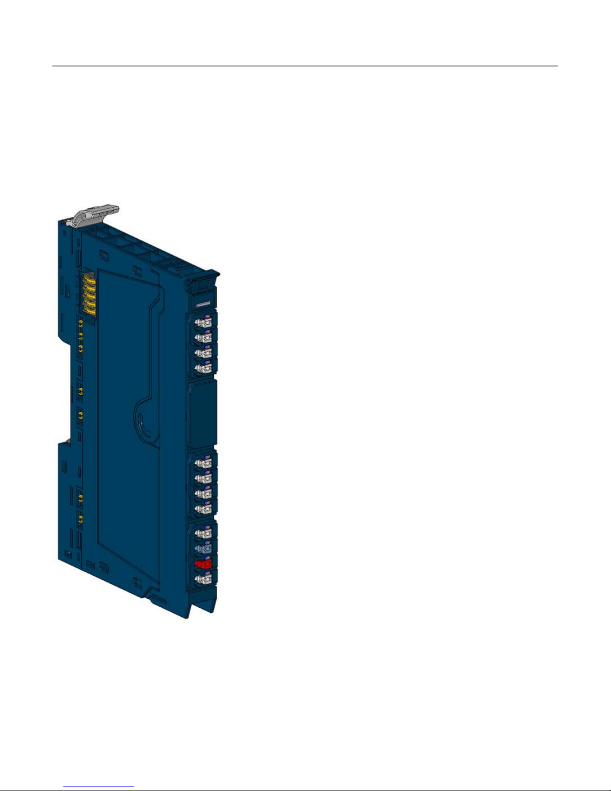
Serial Communication Module EP-5261
Serial Communication Module EP-5261
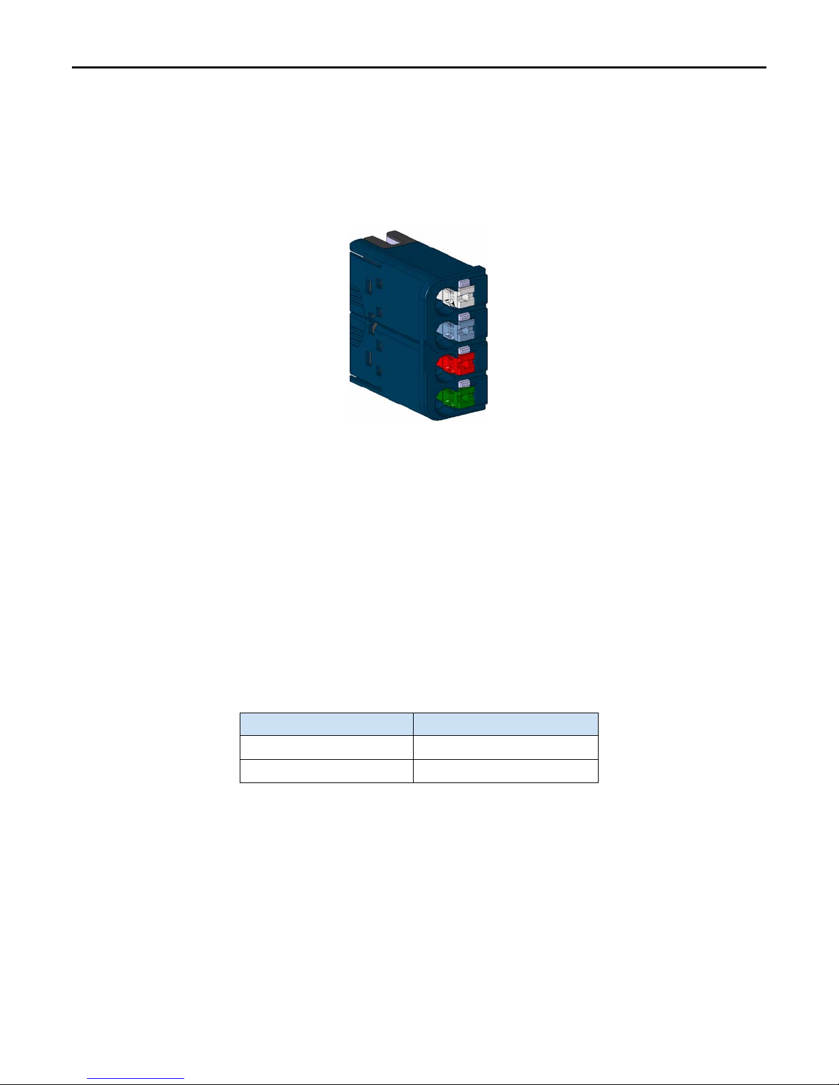
The RSTi-EP Serial Communication (EP-5261) module provides extended
communication options. For example, devices (such as barcode scanners or
printers) can be integrated consistently in RSTi-EP systems using an RS-232,
RS-485, or RS-422 interface. The EP-5261 module presents a solution for
connecting the control cabinet to the field.
The data transfer rate can be parameterised between 300 and 11,5200 bps.
The process data length can be parameterised to be 8 or 16 byte. A
terminating resistor can be parameterised for the RS-485 and RS-422
interface respectively.
The communication status is indicated by two LEDs on the respective plug.
The module electronics supply the connected data terminal device with
power from the input current path (IIN) either with 5 V dc or 24 V dc. Both
supply voltage outputs are protected against over-current.
The module features a type plate, which includes identification information,
the key technical specifications, and a block diagram. Additionally, a QR code
allows for direct online access to the associated documentation. The
software for reading the QR code must support inverted QR codes.
Markers are available as accessories for labelling the equipment. Each I/O
module can be labelled to ensure clear identification when replacing
individual modules or electronic units.
The RSTi-EP station is usually installed on a horizontally positioned DIN-rail.
Installation on vertically positioned DIN rails is also possible.
Modules should to be allowed to de-energize for a minimum 10 seconds after
power down, prior to starting any maintenance activity.
Refer to the RSTi-EP Slice I/O User Manual (GFK-2958) for additional
information.
For power-feed (a software utility available on PME V9.00) requirements, refer
to the RSTi-EP Power Supply Reference Guide.
EP-5261 Module Features
•Spring style technology for ease of wiring
•DIN-rail mounted
•Double-click installation for positive indication of correct installation
•Supports indirect firmware update through the network monitor
•Supports replacement without shutting down the system
September 2016
© 2016 General Electric Company.
*Indicates a trademark of General Electric Company and/or its subsidiaries. All other trademarks are the property of their respective owners.