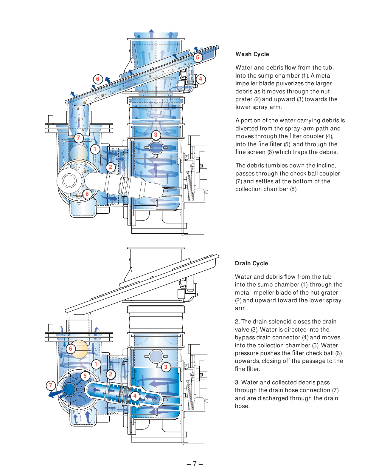
GE 31-9155 How to use

– 2
IMPORTANT SAFETY NOTICE
The information in this service guide is intended for use by
individuals possessing adequate backgrounds of electrical,
electronic, and mechanical experience. Any attempt to repair a
major appliance may result in personal injury and property
damage. The manufacturer or seller cannot be responsible for the
interpretation of this information, nor can it assume any liability in
connection with its use.
WARNING
To avoid personal injury, disconnect power before servicing
this product . If electrical power is required for diagnosis or test
purposes, disconnect the power immediately after performing the
necessary checks.
RECONNECT ALL GROUNDING DEVICES
If grounding wires, screws, straps, clips, nuts, or washers used to
complete a path to ground are removed for service, they must be
returned to their original position and properly fastened.
GE Consumer & Industrial
Technical Service Guide
Copyright © 2007
All rights reserved. This service guide may not be reproduced in whole or in part
in any form without written permission from the General Electric Company.
https://appliancetechmanuals.com

– 3 –
Table of Contents
Calrod Element ................................................................................................................14
Collection Chamber and Sump ........................................................................................13
Component Locator Views............................................................................................... 9
Components.....................................................................................................................12
Filter and Drain System ...................................................................................................16
High Drain Loop/Air Gap..................................................................................................15
Introduction ...................................................................................................................... 5
Main Motor .......................................................................................................................15
Motor-Pump Mechanism..................................................................................................12
Nomenclature................................................................................................................... 4
PowerScrubTM Wash Systems.......................................................................................... 8
Pump Assembly ............................................................................................................... 6
Service Mode ...................................................................................................................15
Spray Arm and Fine Filter Assembly. ...............................................................................12
Spray Arm Base ...............................................................................................................14
Troubleshooting ...............................................................................................................15
Warranty...........................................................................................................................17
Washability Complaints....................................................................................................16
https://appliancetechmanuals.com

– 4
Model Designator
Designates features – the higher
the number, the more features.
G S D 4 0 6 0 N 0 0 S S
Brand
P = Profile
E = General Electric - NATM
G = General Electric
A = Americana
Product Type
CD = Counter Top DW = Dishwasher
SD = Standard SC = Convertible
SM = Spacemaker SS = Compact (18 in.)
RF = Retrofit HD = Home Depot Derivative
Exterior Color
BB = Black
II = Requires Custom Panel
and Handle
SS = Stainless Steel
WW = White
Model Year Designator
Engineering Model Suffix
Model Number
The serial plate of your dishwasher
is located on the tub wall just inside
the door jam.
The mini manual is located behind
the toe plate.
The letter designating
the year repeats every
12 years.
Example:
T - 1974
T - 1986
T - 1998
Serial Number
The first two characters of the serial number
identify the month and year of manufacture.
Example: AM123456S = January, 2007
A- JAN 2007 - M
D - FEB 2006 - L
F - MAR 2005 - H
G - APR 2004 - G
H - MAY 2003 - F
L - JUN 2002 - D
M - JUL 2001 - A
R - AUG 2000 - Z
S - SEP 1999 - V
T - OCT 1998 - T
V - NOV 1997 - S
Z - DEC 1996 - R
Nomenclature
Mini Manual
Nomenclature
Serial Plate
https://appliancetechmanuals.com

– 5 –
Introduction
This technical service guide covers the changes in the standard line of dishwashers. The 2007 standard
dishwashers include 39 models in 12 family groups.
The most significant changes are in the new water distribution system. These changes include the following
features:
New Spray Arm Assembly - has a new spray arm base with locking ring and release tab for removal
New Extra Fine Filter Assembly - filtration up to one-onehundreth of an inch, is self cleaning, and
has 1 screw and a release tab for removal
New Pump Assembly - has a low flow impeller, new grater nut , new arm valve, and a new disposer
blade
New Single Part Collection Chamber - with sump and check ball that works with the fine filter
•
•
•
•
FRONT
Spray Arm
Assembly
Extra Fine Filter
Assembly
Single Part
Collection
Chamber
Pump Assembly
WTR^[[TRcX^]RWP\QTaXbaT\^eTSUa^\cWTbd\_cWTQP[[[cTafX[[0UcTaR^[[TRcX^]RWP\QTaXbaTPbbT\Q[TSc^bd\_U^[[^fbcT_b #T[cTaaT\^eP[_a^RTSdaTP]ScWT]Sa^_cWTQP[[QPRZX]c^cWT
" !" """ !"" !
Base Spray Arm
Right Hand Threads
Rem ove screw
to disassemble
fine filter
assembly from
base spray arm.
Pull tab out to release spray arm.
Push tab in to rem ove fine filter
assembly .
Rem ove the
sum p cover
screws. Slide
sum p cover
to left
https://appliancetechmanuals.com

– 6
Pump Assembly
Sump Chamber
(Behind Collection
Chamber)
Upper Spray Arm Outlet
Nut Grater
Filter Coupler
Fine Filter
Fine Screen
Check Ball Coupler
Metal Impeller Blade
Drain Solenoid
Drain Valve
Bypass Drain Connector
Drain Outlet
Lower Spray Arm
Collection Chamber
Spray Arm Base
Pump Assembly Connector
Main Motor
https://appliancetechmanuals.com

– 7 –
Wash Cycle
Water and debris flow from the tub,
into the sump chamber (1). A metal
impeller blade pulverizes the larger
debris as it moves through the nut
grater (2) and upward (3) towards the
lower spray arm.
A portion of the water carrying debris is
diverted from the spray -arm path and
moves through the filter coupler (4),
into the fine filter (5), and through the
fine screen (6) which traps the debris.
The debris tumbles down the incline,
passes through the check ball coupler
(7) and settles at the bottom of the
collection chamber (8).
1
2
3
4
5
6
7
8
50
1
2
3
4
5
6
7
Drain Cycle
Water and debris flow from the tub
into the sump chamber (1), through the
metal impeller blade of the nut grater
(2) and upward toward the lower spray
arm.
2. The drain solenoid closes the drain
valve (3). Water is directed into the
bypass drain connector (4) and moves
into the collection chamber (5). Water
pressure pushes the filter check ball (6)
upwards, closing off the passage to the
fine filter.
3. Water and collected debris pass
through the drain hose connection (7)
and are discharged through the drain
hose.
https://appliancetechmanuals.com

– 8
5-Level Wash - Models containing an upper
spray arm have 5 wash levels. These models
include the PowerTowerTM spray and the new
lower spray arm.
5-Level Wash - Models containing
PowerShowerTM have 5 wash levels. These
models include the PowerTowerTM spray and the
new lower spray arm.
4-Level Wash - The basic models have 4 wash
levels. These models utilize the PowerTowerTM
spray and the new lower spray arm.
1.
2.
3.
1.
3.2.
PowerScrubTM Wash Systems
https://appliancetechmanuals.com

– 10
Wash Cycle Timer
Inside Door Panel View
Control Board
Interlock Switch Assem bly
Detergent Motor
Detergent Trip Lever
Wiring Harness
Fill Hose
Top Spray Arm Hose*
Drain Outlet
Water Valve
* On some models.
Detergent Trip Lever
Interlock Switch Assem bly
Timer
Control
Electronic
Control
Left Side View (Insulation Removed)
https://appliancetechmanuals.com

– 11 –
Front View
Bottom View
Flood Switch
Sump
Heating Element
Water Valve
Front of Dishwasher
Rear of Dishwasher
Main Motor
Sump & Drain Outlet
Pump Assembly
Spray Arm
Calrod Element
Filter Assembly
Sump Cover
PowerTower Spray
Top Spray Arm Hose
Fill Hose
By pass Drain Connector
Drain Solenoid
https://appliancetechmanuals.com

– 12
Components
Motor-Pump Mechanism
To Remove Motor-Pump Mechanism:
1. Remove the spray arm, fine filter, sump cover,
and cap. Remove all water from sump with a
syringe.
2. Lift up on the edges of the sump boot , squeeze
inward, and push the sump through the opening
in the tub floor.
Note: Use care not to lose the check ball from the
collection chamber passage in the sump.
Spray Arm and Fine Filter Assembly
To Remove Spray Arm and Fine Filter Assembly:
1. Remove the lower rack from the dishwasher.
2. Gently pull the tab back on the base spray arm
and lift the spray arm up and out .
3. Remove the 1/4-in. hex-head screw that
connects the spray arm base to the fine filter
assembly.
4. Gently push the same tab in to lift the fine filter
assembly up and out . (See step 2.)
5. Clean fine filter screen if soil is present .
Note: Ensure that the check ball is clean and not
blocked. It should move up and down freely.
Note: When installing spray arm, make sure the
metal bushing is in the spray arm base. (See photo
below.)
Note: When installing fine filter, make sure the drain
port of the fine filter is engaged to the vertical drain
port of the sump with check ball in between. (See
photo below.)
(Continued next page)
Metal Bushing
Check Ball
Check Ball
https://appliancetechmanuals.com

– 13 –
3. To remove the access panel, remove two 1/4-in.
hex-head screws from the bottom of the panel.
Loosen the 2 Phillips-head screws at the top,
slide the panel to the left , and pull toward y ou.
4. From below the tub, loosen the 1/4 -in. hex-
head clamp from the top spray arm hose (if
applicable). Remove the electrical connections
and remove the 5/16-in. hex-head screw from
the hanger that holds the motor to the tub
frame.
5. Loosen the 5/ 16-in. hex-head clamp from the
bottom spray arm hose. The motor-pump
mechanism can now be removed from under
the dishwasher.
(Continued next page)
Note: If the collection chamber is removed from the
sump, the check ball will fall out .
To assemble the collection chamber and sump, align
the collection chamber tab with the slot in the sump.
This will assure that the check ball will seat properly
when the drain cycle is performed. If the collection
chamber is not alligned properly, the check ball will
not seat and the dishwasher will not drain.
Note: After installing the collection chamber, drop
the check ball into the sump tube from inside the
tub before installing the fine filter.
WARNING: Sharp objects may be in the sump - use
proper safety precautions.
A foreign object trapped between the food grater
and the grater nut will cause noise to occur. Remove
the spray arm and fine filter (see Spray Arm and Fine
Filter Assembly) to access the sump.
Tab Slot
Collection Chamber and Sump
Check Ball
https://appliancetechmanuals.com

– 14
Calrod Element
To Remove Calrod Element:
1. Disconnect the power to the dishwasher.
2. To remove the access panel, remove two 1/ 4-in.
hex-head screws from the bottom of the panel.
Loosen the 2 Phillips-head screws at the top,
slide the panel to the left , and pull toward y ou.
3. Remove the Calrod terminals and unscrew the
two 13/16-in. Calrod nuts counterclockwise.
4. Remove the 3 Calrod supports.
5. Lift and remove the Calrod.
Spray Arm Base
To Remove the spray arm base:
1. Remove the spray arm and fine filter assemblies.
2. Insert a large flat-blade screwdriver into the
opening in the back of the spray arm base.
3. Engage the screwdriver blade with the
molded filter coupler and turn the base
counterclockwise.
https://appliancetechmanuals.com

– 15 –
Troubleshooting
Service Mode
C78B38B7F0B74A8B?A>6A0<<43F8C70B4AE824<>34C>083C74C427=8280=8=CA>D1;4B7>>C8=6C7438B7F0B74A40272><?>=4=C<0H142H2;43C>34C42C858C8B5D=2C8>=8=62>AA42C;H2><?>=4=CB0A42H2;431H?A4BB8=6:4H?03BC>C74;45C>5C74BC0ACA4B4C:4H?03DB4C74<0CA8G14;>FC>34C4A<8=47>FC>2H2;440272><?>=4=CC>4=C4AB4AE824<>34)?A4BB:4H?03(0=3:4H?03 B8<D;C0=4>DB;H5>A$B42>=3BC>4G8CB4AE824<>34)?A4BBC74BC0ACA4B4C:4H?030C0=HC8<4C>4G8C=>C4)0UcTa$\X]dcTb^UX]PRcXeXchcWTbTaeXRT\^STfX[[Pdc^\PcXRP[[hcda]^UU=>C4)FWT]PR^\_^]T]cXbPRcXePcTSX]cWTB4AE824<>34cWT^dc_dcfX[[R^]cX]dTc^aT\PX]PRcXeT>=d]cX[cWT<PgX\d\cX\TWPbTg_XaTS^aP]^cWTaZTh_PSXb_aTbbTSBTaeXRT<^STCTbc<PcaXg:Th_PS3TbRaX_cX^]CX\TX]BTR^]Sb 0RcXePcTb<PX]?d\_ !0RcXePcTb0dgX[XPah?d\_%(0RcXePcTb3aPX]B^[T]^XS%'0RcXePcTb3TcTaVT]c<^Sd[T"&0RcXePcTbFPcTaEP[eT%%0RcXePcTb7TPcX]V4[T\T]c !$0RcXePcTb<PX]?d\_ !BC0ACA4B4CDbTSc^4G8CBTaeXRT<^ST=>C4)8=3820C4B:4H?03DB43>=;H>=B><4<>34;BF78;4C78B:4H?03<0H=>C14E8B81;4C748=3820C43B?024B7>D;30;F0HB14DB430B0:4H?03
£änÇÈxÎ{Ó£9Ê-/" -
[[
High Drain Loop/ Air Gap
A high drain loop/ air gap is necessary with the new
water distribution system. Without a high drain loop
/air gap, the dishwasher will drain during the wash
cycle due to a small amount of pump pressure in
the extra fine filter.
Main Motor
The pump motor on models with the new water
distribution system starts and stops during the
wash cycle. The pump motor stops to allow the
drain valve to fully open at the end of a drain cycle.
Service Mode Test Matrix*
Keypad Description Time in Seconds* *
10 Activates Main Pump 120
9 Activates Drain Solenoid 6
8 Activates Detergent Cup and
Rinse Agent Dispenser
30
7 Activates Water Valve 60
6 Activates Heating Element 120
START/ RESET Used to EXIT Service Mode
Note: The Mini-manual supplied with the dishwasher may not be totally accurate regarding the service
mode test matrix.
https://appliancetechmanuals.com

– 16
Washability Complaints
Hot Water – Ample supply of water at 120°F
minimum temperature is necessary. Do not use
dishwasher soon after using clothes washer, or
filling bathtub.
Loading – Consult Owner’s Manual on loading
procedures.
Amount of Water - Make certain dishwasher is
level. Allow dishwasher to fill normally for the first fill
and drain completely . Allow dishwasher to complete
the second fill and check water level. Water should
cover the bottom of the flood float cover. If water
level is low, check for clogged screen in water valve,
and check float switch.
Detergent Cup Leakage – Some moisture in cup is
normal. It must not be soaking wet and oozing out
and down the inner door panel. Refer to section on
detergent cup if leaking.
Proper Amount of Detergent – Use full detergent
cup of fresh detergent in hard water. Use only
enough detergent to get good wash performance in
soft water.
Rinse Agent – Use rinse agent if spotting is a
problem.
Water Valve – Check valve for intermittent
operation. Valve coil can be tested directly.
Spray Arm – Check to be sure spray arm spins
freely and jets are not clogged.
Filter and Drain System
Will Not Pump Out
1. Check routing of hose system. It must be free
from kinks.
2. Check for blocked or partially blocked drain line
and air gap.
3. Check operation of check ball. Check ball should
be up in drain and down in circulation.
Note: If the collection chamber is not alligned
properly, the check ball will not seat and the
dishwasher will not drain.
MOTOR-PUMP MECHANISM
Motor Stalled-Hums
1. Disconnect Power. Try to turn motor shaft
clockwise to determine if seal is stuck and
can be broken loose. If motor shaft cannot be
turned, cutter blade may be bound up. Proceed
to step 2.
2. On inside of dishwasher, remove sump cover.
Remove the cap in sump and reach down
into the sump. Check for blockages, such as
bone, wire ties, etc. If it contains debris, clean
thoroughly . If motor shaft cannot be turned,
remove mechanism.
https://appliancetechmanuals.com

– 17 –
Warranty
What Is Not Covered:
For The Period Of: GE Will Replace:
One Year Any part of the dishwasher which fails due to a defect in materials or workmanship. During
From the date of the this limited one-year warranty, GE will also provide, free of charge, all labor and in-home service
original purchase to replace the defective part.
GE Dishwasher Warranty
■Service trips to your home to teach you how to use
the product.
■Improper installation, delivery or maintenance.
■Failure of the product if it is abused, misused, or used for
other than the intended purpose or used commercially.
■Replacement of house fuses or resetting of circuit
breakers.
■Damage to the product caused by accident, fire, floods
or acts of God.
■Incidental or consequential damage caused by possible
defects with this appliance.
■Cleaning or servicing of the air gap device in the
drain line.
■Damage caused after delivery.
■Product not accessible to provide required service.
This warranty is extended to the original purchaser and any succeeding owner for products purchased for
home use within the USA. If the product is located in an area where service by a GE Authorized Servicer is not
available, you may be responsible for a trip charge or you may be required to bring the product to an Authorized GE
Service location. In Alaska, the warranty excludes the cost of shipping or service calls to your home.
Some states do not allow the exclusion or limitation of incidental or consequential damages. This warranty
gives you specific legal rights, and you may also have other rights which vary from state to state. To know
what your legal rights are, consult your local or state consumer affairs office or your state’s Attorney General.
Warrantor: General Electric Company. Louisville, KY 40225
All warranty service provided by our Factory Service Centers,
or an authorized Customer Care®technician. To schedule
service, on-line, 24 hours a day, visit us at ge.com, or call
800.GE.CARES (800.432.2737). Please have serial number and
model number available when calling for service.
Staple your receipt here.
Proof of the original purchase
date is needed to obtain service
under the warranty.
EXCLUSION OF IMPLIED WARRANTIES—Your sole and exclusive remedy is product repair as provided in this Limited
Warranty. Any implied warranties, including the implied warranties of merchantability or fitness for a particular
purpose, are limited to one year or the shortest period allowed by law.
Note: To verify the dishwasher warranty in effect , refer to the Use & Care publication for the model number
being serviced.
https://appliancetechmanuals.com
Other manuals for 31-9155
1
Table of contents
Other GE Dishwasher manuals