The
sump
cover
has been redesigned, although
the
operation
is
still
the
same.
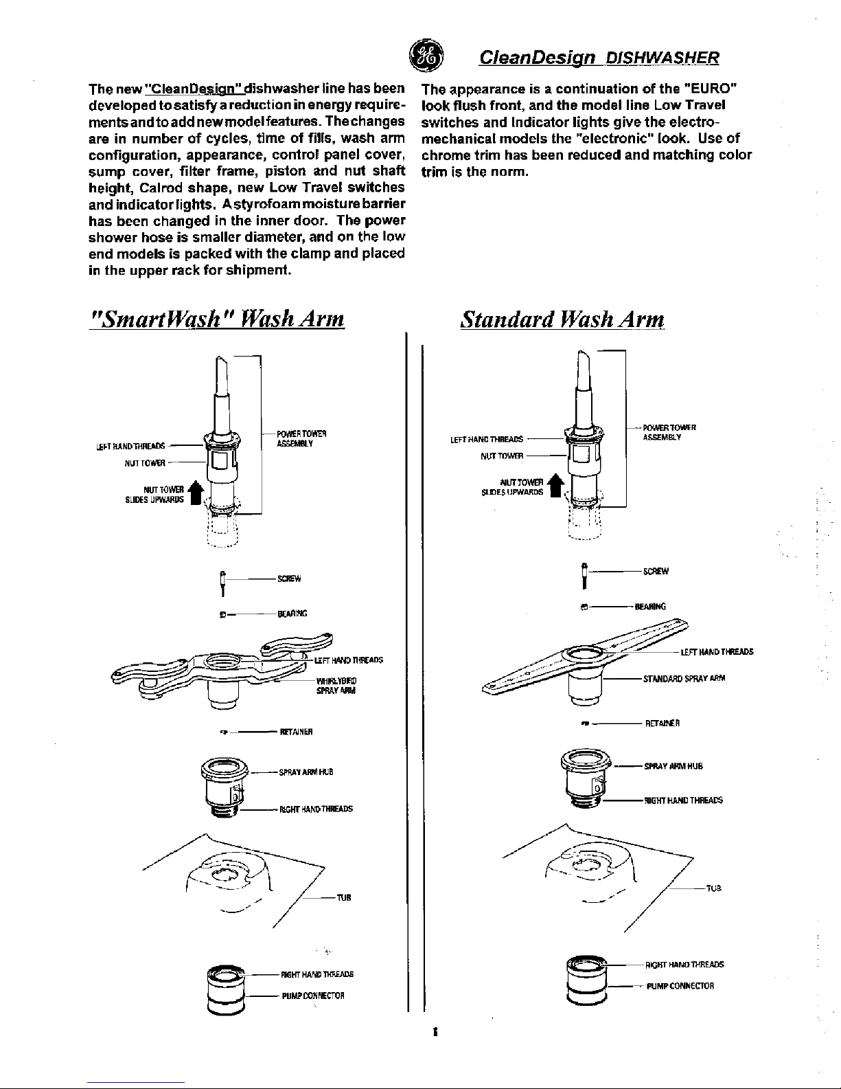
CleanDesign DISHWASHER
MOTOR STALLED-HUMS
1. Remove power.
Try
to
turn
fan blade
clock-
wise
to
determine
if
seal is
tuck
and can
be
broken loose.
If
motor
shaft
can
not
beturned,
cutter
blade may
be
bound up. Proceed
to
step
#2.
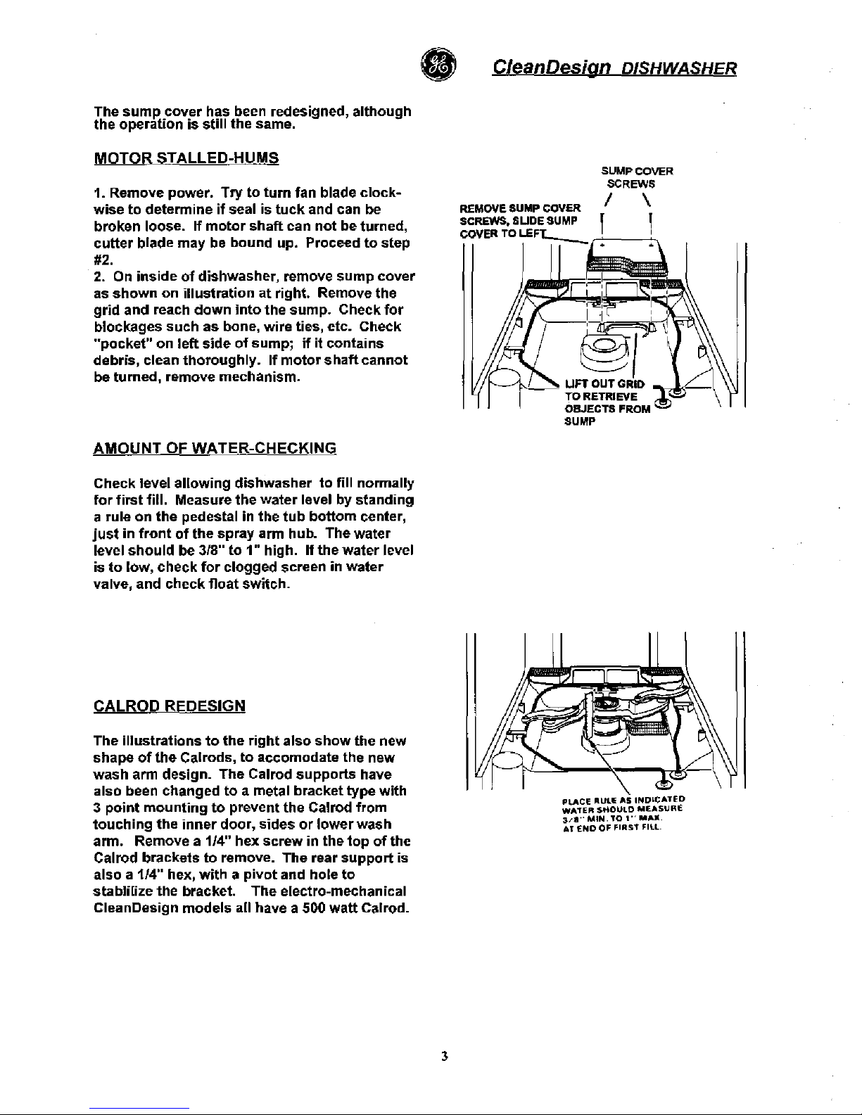
2.
On
inside
of
dishwasher, remove
sump
cover
as
shown
on
illustration
at right. Remove the
grid
and
reach
down
into
the
sump.
Check
for
blockages
such
as bone, wire ties, etc. Check
"pocket"
on
left
side
of
sump;
if
it
contains
debris, clean
thoroughly.
If
motor
s
haft
cannot
be turned, remove mechanism.
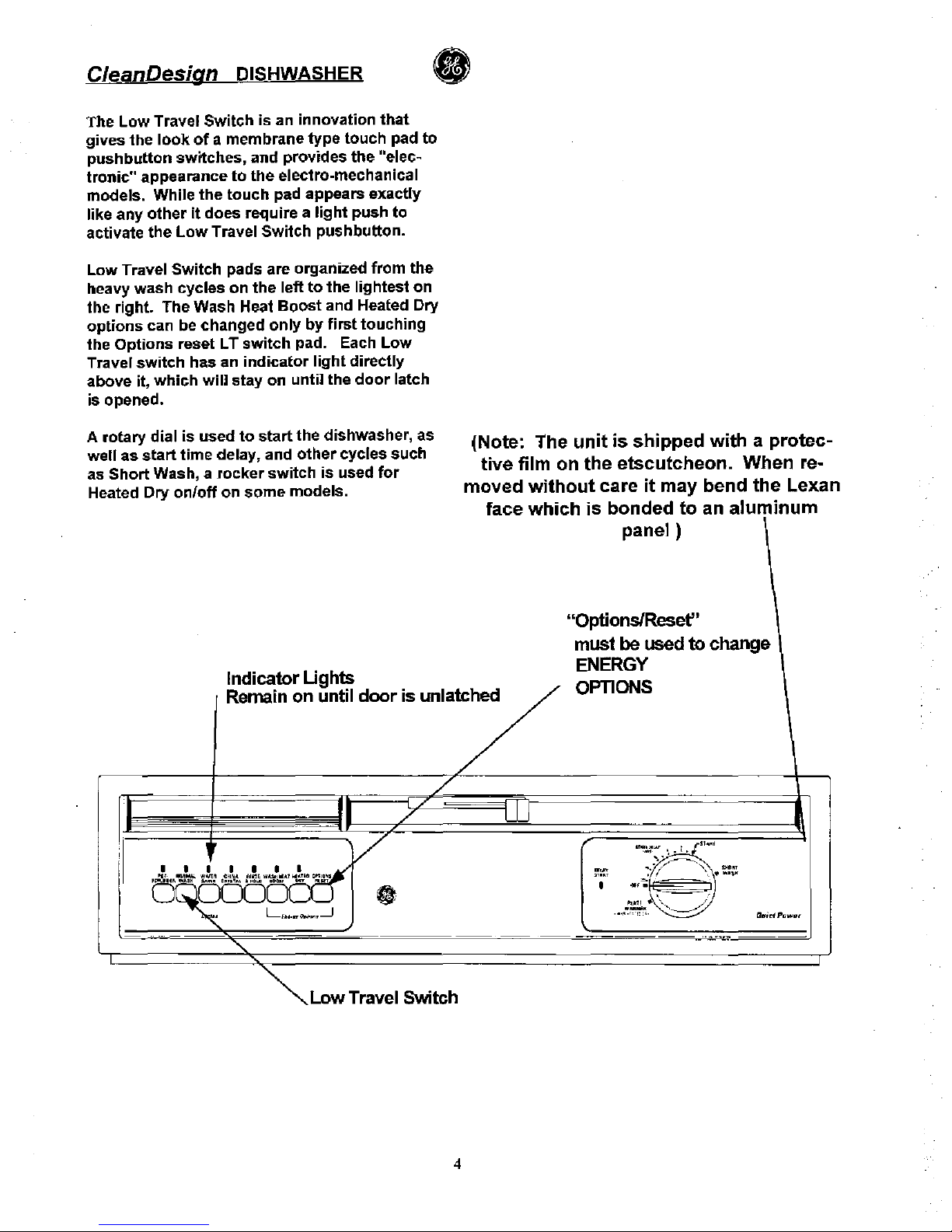
AMOUNT OF WATER-CHECKING
Check level
allowing
dishwasher
to
fill normally
for
first
fill. Measure
the
water
level by standing
arule
on
the
pedestal in
the
tub
bottom
center,
just
in
front
of
the
spray arm hub. The water
level
should
be 3/S"
to
1"
high.
If
the
water
level
is
to
low,
check
for
clogged screen in
water
valve, and check
float
switch.
REMOVE SUMP
covER
SCREWS.
SWOE
SUMP
COVER TO
LEFt-
SUMP COVER
SCREWS
/ \
I I
CALROD REDESIGN
The
illustrations
to
the
right
also
show
the
new
shape
of
the
Calrods,
to
accomodate the new
wash
arm design. The Calrod
supports
have
also been changed
to
ametal bracket
type
with
3
point
mounting
to
prevent the Calrod
from
touching
the
inner
door,
sides
or
lower
wash
arm. Remove a
114"
hex
screw
in
the
top
of
the
Calrod brackets
to
remove. The rear
support
is
also
a1/4" hex,
with
a
pivot
and hole
to
stablilize the bracket. The electro-mechanical
CleanDesign
models
all have a500
watt
Calrod.
3
PLACE
'lUll'
AS
INDLeATED
WATER
$KOULD
MEASURE
,/lI··MIN.TO
'··M
......
At
!NO
OF
FIRst
Fill