GE GDT550HSDSS User manual

GE Appliances
Installation Instructions
Built-In Dishwasher
If you have questions, call 800.GE.CARES (800.432.2737) or visit our Website at: GEAppliances.com.
In Canada, please call 1.800.561.3344 or visit www.geappliances.ca
IMPORTANT –The dishwasher MUST be installed
to allow for future removal from the enclosure if service is
required.
Care should be exercised when the appliance is installed or
removed, to reduce the likelihood of damage to the power
supply cord.
If you received a damaged dishwasher, you should immediately
contact your dealer or builder.
Optional Accessories – See the Owner’s Manual for available
custom panel kits.
FOR YOUR SAFETY
Read and observe all CAUTIONS and WARNINGS shown
throughout these instructions. While performing
installations described in this booklet, gloves, safety glasses
or goggles should be worn.
READ CAREFULLY.
KEEP THESE INSTRUCTIONS.
IMPORTANT –Observe all governing codes and
ordinances.
Note to Installer – Be sure to leave these instructions for the
consumer’s and local inspector’s use.
Note to Consumer – Keep these instructions with your
Owner’s Manual for future reference.
Skill Level – Installation of this dishwasher requires
basic mechanical, electrical and plumbing skills. Proper
installation is the responsibility of the installer. Product
failure due to improper installation is not covered under
the GE Appliance Warranty. See warranty information.
Completion Time – 1 to 3 Hours. New installations require
more time than replacement installations.
BEFORE YOU BEGIN
Read these instructions completely and
carefully.
31-31506-2 10-12 GE

TOOLS YOU WILL NEED:
■Phillips-head screwdriver
■1/4" and 5/16" nutdriver
■6" Adjustable wrench
■Level
■Carpenter's square
■Measuring tape
■Safety glasses
■Flashlight
■ %XFNHWWRFDWFKZDWHUZKHQÀXVKLQJWKHOLQH
■15/16" socket (optional for skid removal)
■Gloves
■Pliers
For New Installations Only:
■Tubing cutter
■Drill and appropriate bits
■Hole saw set
90° Elbow,
Ferrule and
Compression Nut
Hot Water Line
Hand
6KXW2ȹ
Valve
Side Trim Pieces
(on some models)
Hole Saw Set
Level
Thread
Seal Tape
Air Gap
Strain Relief
Drain Hose
Hose Clamp
#8 Hex-Head Mounting
Bracket Screws
1/4" and 5/16"
Nutdriver
15/16" Socket
Bucket
Tubing Cutter
Drill and Bits
Flashlight
Gloves
Phillips-Head
Screwdriver Carpenter's
Square
6"
Adjustable
Wrench Safety Glasses
Pliers
Installation Preparation
2
Drain Hose Hanger
Measuring Tape
PARTS SUPPLIED
IN INSTALLATION PACKAGE:
■Junction box cover and #10 hex-head screw
■Hose clamp
■Drain hose (approximately 78" long)
■Drain hose hanger
■2 #8-18 hex head screws to secure brackets to
washer tub frame
■2 Plug buttons
■2 side trim pieces (some models)
■2 mounting brackets for wood countertops or side
cabinets
■2 #8-18 x 5/8" Phillips special head screws, to secure
dishwasher to underside of countertop or to side
cabinets
■Literature, samples and/or coupons
MATERIALS YOU WILL NEED:
■Ferrule, compression nut and 90° elbow (3/8"NPT
external thread on one end, opposite end sized
to fit water supply)
■Thread seal tape
■UL-listed wire nuts (3)
■Masking Tape
Materials Needed for
New Installations:
■Air gap for drain hose, if required
■Waste tee for house plumbing, if applicable
■Electrical cable or power cord
■Screw-type hose clamps
■Strain relief for electrical connection
■Hand shut-off valve (recommended)
■Water line–3/8" minimum copper tubing
■GPF12L drain hose (12' long), if needed
Junction
Box Cover
#10
Hex-Head
Junction
Box Screw
1/2" long
Optional
12' Drain Hose
GPF12L
Hose Clamps
Waste Tee
Electrical Cable
(or Power Cord, if applicable)
Wire Nuts (3)
Mounting
Brackets
#8 Phillips
Special
Head Screws
5/8" long
Plug Buttons
Masking Tape
(if applicable)

Method 1 – Air Gap with Waste Tee or Disposer
An air gap must be used when required by local codes and ordi-
nances. The air gap must be installed according to manufacturer’s
instructions.
PREPARE DISHWASHER ENCLOSURE
7KHURXJKFDELQHWRSHQLQJPXVWEHDWOHDVWGHHS
wide and approximately 34-1/2" high from floor to underside
of the countertop.
CLEARANCES: When
installed into a corner,
allow 2" min. clearance
between dishwasher
and adjacent cabinet,
wall or other appliances.
Allow 28-3/8" min. clear-
ance from the front of
the dishwasher for door
opening. Figure B.
DRAIN REQUIREMENTS
)ROORZORFDOFRGHVDQGRUGLQDQFHV
'RQRWH[FHHGGLVWDQFHWRGUDLQ
NOTE: Air gap must be used, if waste tee or disposer
connection is less than 18" above floor to prevent siphoning.
DETERMINE DRAIN METHOD
The type of drain installation depends on the following
questions.
■Do local codes or ordinances require an air gap?
■Is waste tee less than 18" above floor?
If the answer to either question is YES, Method 1 MUST
be used.
,IWKHDQVZHUVDUH12HLWKHUPHWKRGPD\EHXVHG
CABINET PREPARATION
'ULOODGLDPHWHUKROHLQWKHFDELQHWZDOOZLWKLQ
the shaded areas shown in Figure A for the drain hose
connection. The hole should be smooth with no sharp edges.
IMPORTANT –When
connecting drain line to disposer,
check to be sure that drain plug has
been removed. DISHWASHER WILL
NOT DRAIN IF PLUG IS LEFT IN PLACE. Method 2 – “High Drain Loop” with Waste Tee or Disposer
Tip: Avoid unnecessary service call charges.
Always be sure disposer drain plug has been removed before
attaching dishwasher drain hose to the disposer.
Figure D
7KHGLVKZDVKHUPXVWEHLQVWDOOHGVRWKDWGUDLQKRVHLVQR
more than 12' in length for proper drainage.
7KHGLVKZDVKHUPXVWEHIXOO\HQFORVHGRQWKHWRSVLGHVDQG
back, and must not support any part of the enclosure.
24"
Min.
This Wall Area
must be Free
of Pipes or
wires
Plumbing and Electric Service
Must Enter Inside This Area
4"
24"
Min.
6"
Cabinets
Square
and
Plumb
+
34-1/2" 1/4"
Underside of
Countertop
to Floor
32"
Min.
18"
Min.
Drain Hose Hanger
Figure B
Clearance for Door
Opening 2" Minimum
Countertop
Dishwasher
28-3/8"
Figure A
Figure C
Installation Preparation
3
Remove
Drain
Plug
32"
Min.
18"
Min.
Drain Hose Hanger
WARNING:
7RUHGXFHWKHULVNRIHOHFWULFVKRFN¿UHRULQMXU\WRSHUVRQVWKH
installer must ensure that the dishwasher is completely enclosed at
the time of installation.
ADVERTENCIA:
Para reducir el riesgo de descarga eléctrica, incendio o lesiones a
personas, el instalador debe asegurarse de que el lavaplatos esté
completamente cerrado en el momento de la instalación.

For models equipped with power cord: Do not modify the plug
provided with the appliance; if it will not fit the outlet, have a
proper outlet installed by a qualified technician.
Cabinet Preparation & Wire Routing
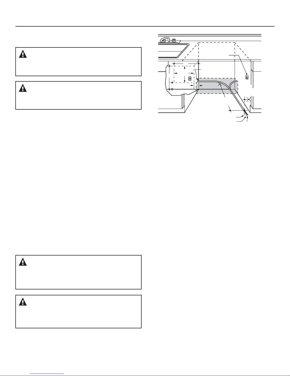
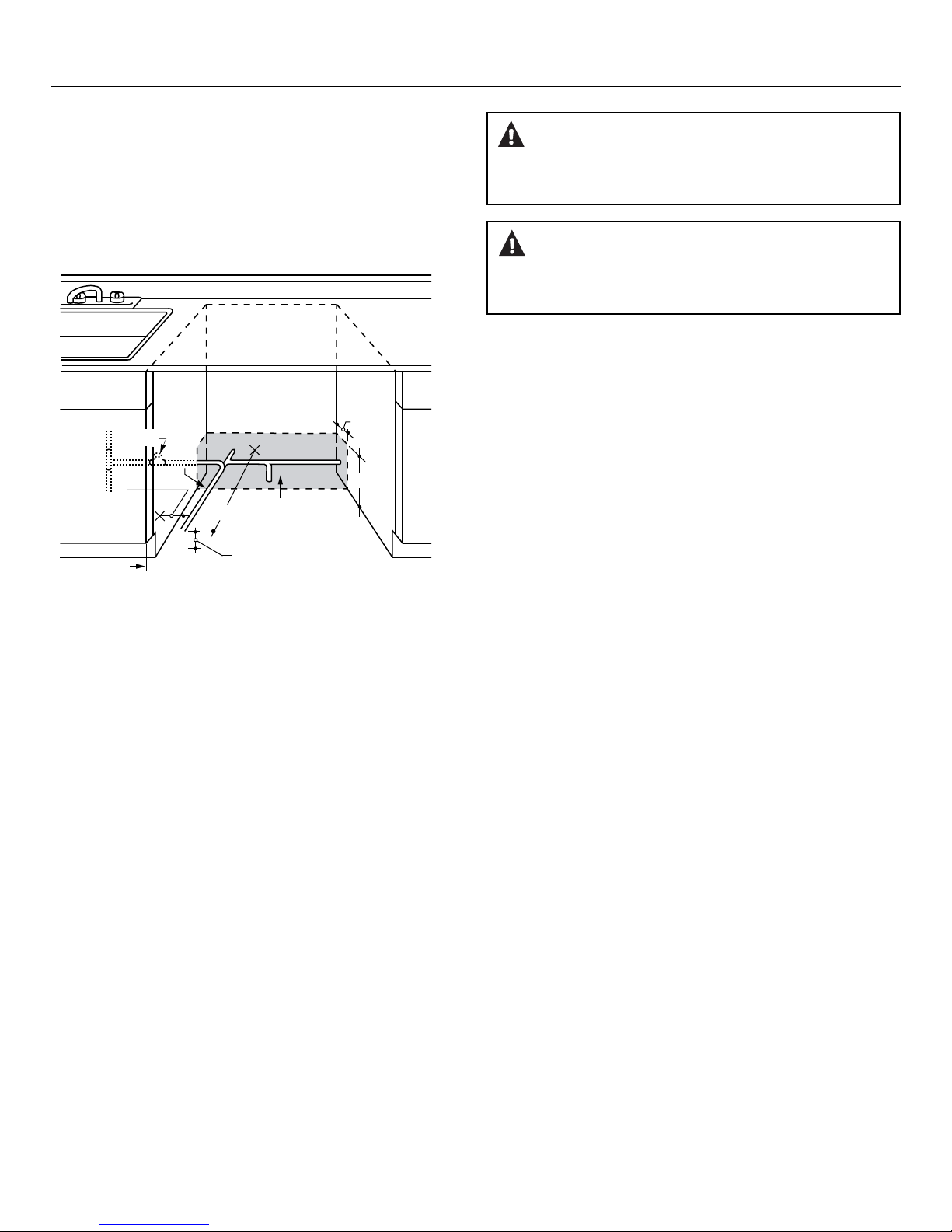
7KHZLULQJPD\HQWHUWKHRSHQLQJIURPHLWKHUVLGHUHDURUWKH
floor within the shaded area illustrated above in Figure E and
defined in Figure A.
&XWDPD[LPXPGLDPHWHUKROHWRDGPLWWKHHOHFWULFDO
cable. Edges of hole should be smooth and rounded.
Permanent wiring connections may pass through the same
hole as the drain hose and hot water line, if convenient. If
cabinet wall is metal, the hole edge must be covered with a
bushing.
NOTE: Power cords with plug must pass through a separate
hole.
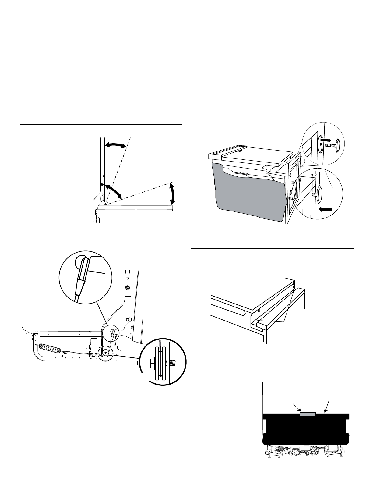
Electrical Connection to Dishwasher
Electrical connection is on the right front of dishwasher.
)RUSHUPDQHQWFRQQHFWLRQVWKHFDEOHPXVWEHURXWHGDV
shown in Figure E. Cable must extend a minimum of 24" from
the rear wall.
)RUSRZHUFRUGFRQQHFWLRQVLQVWDOODSURQJJURXQGLQJ
type receptacle in the sink cabinet rear wall, 6" min. or 18"
maximum from the opening, 6" to 18" above the floor.
8VHWD06X10020 Dishwasher Power Cord Kit.
PREPARE ELECTRICAL WIRING
Electrical Requirements
7KLVDSSOLDQFHPXVWEHVXSSOLHGZLWK9+]DQG
connected to an individual properly grounded branch circuit,
protected by a 15- or 20-ampere circuit breaker or time-delay
fuse.
:LULQJPXVWEHZLUHZLWKJURXQGDQGUDWHGIRU&)
,IWKHHOHFWULFDOVXSSO\GRHVQRWPHHWWKHDERYHUHTXLUHPHQWV
call a licensed electrician before proceeding.
Grounding Instructions–Permanent Connection
This appliance must be connected to a grounded metal,
permanent wiring system, or an equipment-grounding
conductor must be run with the circuit conductors and be
connected to the equipment-grounding terminal or lead on
the appliance.
Grounding Instructions–Power Cord Models
This appliance must be grounded. In the event of a malfunction
or breakdown, grounding will reduce the risk of electric shock
by providing a path of least resistance for electric current.
This appliance is equipped with a cord having an equipment-
grounding conductor and a grounding plug. The plug must
be plugged into an appropriate outlet that is installed and
grounded in accordance with all local codes and ordinances.
White
18"
6"
24"
from Wall
3"
from
Cabinet
Alternate
Receptacle
Location
Ground
Black
1-1/2" Dia. Hole (Max.)
18"
6"
Receptacle
Location
Area
Figure E
Installation Preparation
4
WARNING:
FOR PERSONAL SAFETY: Remove house fuse or open circuit breaker
before beginning installation. Do not use an extension cord or
adapter plug with this appliance.
ADVERTENCIA:
PARA SEGURIDAD PERSONAL: Quite el fusible o abra el interruptor
de circuitos antes de comenzar la instalación. No utilice un cable
de extensión o un enchufe adaptador con este artefacto.
WARNING:
The improper connection of the equipment grounding conductor
FDQUHVXOWLQDULVNRIHOHFWULFVKRFN&KHFNZLWKDTXDOL¿HG
electrician or service representative if you are in doubt that
the appliance is properly grounded.
ADVERTENCIA:
La conexión inadecuada del conductor de conexión a tierra del
equipamiento puede provocar un riesgo de descarga eléctrica.
&RQVXOWHDXQHOHFWULFLVWDFDOL¿FDGRRUHSUHVHQWDQWHGHVHUYLFLR
técnico si tiene dudas sobre la correcta conexión a tierra del aparato.

PREPARE HOT WATER LINE
7KHOLQHPD\HQWHUIURPHLWKHUVLGHUHDURUIORRUZLWKLQWKH
shaded area shown in Figure F.
7KHOLQHPD\SDVVWKURXJKWKHVDPHKROHDVWKHHOHFWULFDO
cable and drain hose. Or, cut an additional 1-1/2" diameter
hole to accommodate the water line. If power cord with plug
is used, water line must not pass through power cord hole.
Figure F
Water Line Connection
7XUQRIIWKHZDWHUVXSSO\
,QVWDOODKDQGVKXWRIIYDOYHLQDQDFFHVVLEOHORFDWLRQVXFK
as under the sink. (Optional, but strongly recommended and
may be required by local codes.)
:DWHUFRQQHFWLRQLVRQWKHOHIWVLGHRIWKHGLVKZDVKHU,QVWDOO
the hot water inlet line, using no less than 3/8" copper tubing.
Route the line as shown in Figure F and extend forward at
least 19" from rear wall.
$GMXVWZDWHUKHDWHUIRU)WR)WHPSHUDWXUH
)OXVKZDWHUOLQHWRFOHDQRXWGHEULV
7KHKRWZDWHUVXSSO\OLQHSUHVVXUHPXVWEH36,
Turn page to begin dishwasher installation.
6"
4"
Cabinet Face
Shut-off
Valve
2" From Floor
19" From Wall
2"
From
Cabinet
1-1/2" Dia.
Hole
Hot
Installation Preparation
5
CAUTION:
Do not remove wood base until you are ready to install the
dishwasher. The dishwasher will tip over when the door is
opened if base is removed.
PRECAUCIÓN:
No quite la base de madera hasta que esté listo para instalar el
lavaplatos. Si se quita la base, el lavaplatos se volcará cuando
se abra la puerta.

Sound Barrier
Bottom Front View
Tape
:LWKGLVKZDVKHURQWKH
wood base, check the
door balance by opening
and closing the door.
'RRULVSURSHUO\EDODQFHG
if, when opened, it self
closes within 20° from
vertical, stays in position
from 20° to 70° and falls
fully open beyond 70°.
Dishwasher Installation
Figure G
6FUHZOHYHOLQJOHJVEDFNLQWRWKHGLVKZDVKHUIUDPH
approximately 1/2" from frame as shown.
Approx.
1/2"
STEP 3: REMOVE WOOD BASE,
INSTALL LEVELING LEGS
IMPORTANT – 'RQRWNLFNRȺZRRGEDVH
Damage will occur.
0RYHWKHGLVKZDVKHUFORVHWRWKHLQVWDOODWLRQORFDWLRQDQGOD\
it on its back.
5HPRYHWKHOHYHOLQJOHJVRQWKHXQGHUVLGHRIWKHZRRGEDVH
with a 15/16" socket wrench.
'LVFDUGEDVH
STEP 1: PREPARATION
Locate the items in the installation package:
6FUHZV
-XQFWLRQER[FRYHU
'UDLQKRVHDQGFODPS
0RXQWLQJEUDFNHWV
7ULPSLHFHVRQVRPHPRGHOV
'UDLQKRVHKDQJHU
2ZQHUV0DQXDO
3URGXFWVDPSOHVDQGRUFRXSRQV
Figure H
Toekick
Remove 2
Toekick Screws
STEP 4: REMOVE TOEKICK
5HPRYHWKHWRHNLFNVFUHZVDQGWRHNLFN6HWDVLGHIRUXVHLQ
Step 22.
Figure I
6
Tip: Make sure door opens and closes smoothly.
Check door opening and closing. If door does not open easily or
falls too quickly, check spring cable routing. The cable is held in
place by “shoulders” on the pulley. Check to be sure cable has
not slipped over the pulley shoulders and is routed as shown.
6LGH9LHZ
Make sure
pulley cable
is within
pulley
shoulders
)URQW9LHZ
,IQHFHVVDU\LQFUHDVHRUGHFUHDVHWHQVLRQDVVKRZQ/DWFK
door and adjust both springs to the same tension setting to
correct balance.
STEP 2: CHECK DOOR BALANCE
Door
closes
within
20°
Door stays in
position from
20° to 70°
Door falls fully
open beyond 70°
6LGH9LHZ
STEP 5: POSITION SOUND BARRIER
(on some models)
Skip this step if the sound
barrier is not assembled
to the dishwasher.
Lift the sound barrier and
tape to the door front with
masking tape. This will
hold the sound barrier up
and out of the way during
installation.

STEP 7: INSTALL DRAIN HOSE TO DRAIN
LOOP
Connect drain loop end to drain hose using the screw clamp
as shown in the figure.
STEP 6: INSTALL 90° ELBOW
:UDSDHOERZZLWK
thread seal tape.
7KUHDGHOERZ
onto the water valve.
'RQRWRYHUWLJKWHQ
elbow. Water valve
bracket could
bend or water valve
fitting could break.
3RVLWLRQWKHHQGRI
the elbow to face the
rear of the dishwasher.
Figure K
Dishwasher Installation
7
Front of Dishwasher
:DWHU9DOYH
Bracket
90° Elbow
Fill Hose
Thread
Seal
Tape
Figure L
Power Cord
(If Used)
Insulation
Blanket Water
Line
Maximum Drain Hose
Length 10'
House
Wiring
Drain
Hose
Figure N
STEP 9:
INSTALL DRAIN HOSE,
THROUGH CABINET
3RVLWLRQGLVKZDVKHULQIURQWRIFDELQHWRSHQLQJ,QVHUWGUDLQ
hose into the hole in cabinet side. If a power cord is used,
guide the end through a separate hole.
STEP 8: POSITION WATER LINE
AND HOUSE WIRING
3RVLWLRQZDWHUVXSSO\OLQHDQGKRXVHZLULQJRQWKHIORRURI
the opening to avoid interference with base of dishwasher
and components under dishwasher.
Figure M
Water
Line House
Wiring
4" 4"
6"
6"
7LS3UHYHQWXQQHFHVVDU\VHUYLFHFDOOFKDUJHVIRU¿OOGUDLQRU
noise concerns.
Position utility lines so they do not interfere with anything
under or behind the dishwasher.

Bracket
Dishwasher Installation
STEP 10: SLIDE DISHWASHER THREE-FOURTHS
OF THE WAY INTO CABINET
IMPORTANT – Do not push against front panel with
knees. Damage will occur.
*UDVSWKHVLGHVRIWKHIURQWSDQHODQGVOLGHGLVKZDVKHULQWR
the opening a few inches at a time.
$V\RXSURFHHGSXOOWKHGUDLQKRVHWKURXJKWKHRSHQLQJ
under the sink. Stop pushing when the dishwasher extends
about 6 inches forward of adjacent cabinets.
0DNHVXUHGUDLQKRVHLVQRWNLQNHGXQGHURUEHKLQGWKH
dishwasher.
0DNHFHUWDLQWKHKRXVHZLULQJGUDLQOLQHDQGZDWHUOLQHGR
not interfere with components under dishwasher.
Figure O
Do not push against
front door panel with
knee. Damage to the
door panel will occur.
8
Figure P
STEP 11: INSTALL TRIM PIECES
(on some models)
Skip this step if trim is not supplied with the dishwasher.
In this step you will need the trim pieces set aside in Step 1.
3RVLWLRQWKHWULPSLHFHVVRWKHOLSVIDFHWRZDUGWKH
dishwasher door.
6HOHFWDWULPSLHFHDQGSUHVVLWRQWRWKHOHIWVLGHWXEÀDQJH
Start with the top edge and press the trim piece completely
RQWRWKHWXEÀDQJHDV\RXPRYHWRZDUGVWKHERWWRP5HSHDW
IRUWKHULJKWVLGHWXEÀDQJHWULPSLHFH
Top View
Trim
Strip
Trim
Strip
If you would like to order the Trim Kit from GE Service, please
call 800.GE.Cares and request part number WD08X10094 for
BB models or WD08X10096 for WW or CC models.
STEP 12: INSTALL MOUNTING BRACKETS
You will need the mounting brackets and 2 #8 hex-head screws
set aside in Step 1.
You must install the mounting brackets onto the dishwasher
tub frame top or sides prior to sliding the dishwasher into place
under the countertop.
Install mounting brackets on top if the underside of
countertop is wood or wood-like material that accepts screws:
IMPORTANT - After installing brackets and before
closing the dishwasher door, adjust the brackets by bending
them up as needed, so that they do not contact the top of the
dishwasher door and cause damage.
Dishwasher
tub frame
#8 Bracket
Screw
,I\RXDUHLQVWDOOLQJWKHGLVKZDVKHUXQGHUDFRXQWHUZLWKD
short overhang, the countertop brackets may extend beyond
the edge of the counter. If this is the case, remove the excess
length by repeatedly bending the brackets at the front notch
only until they break.
Install mounting brackets on sides if the countertop is
granite or similar material that will not accept wood screws:
%UHDNRȺIURQWSRUWLRQRIWKHWDEZLWKSOLHUVDWWKHORFDWLRQ
shown.
3RVLWLRQWKHOHIWKDQGVLGHEUDFNHWDVVKRZQ5HSHDWZLWKWKH
right bracket.
Dishwasher
tub frame
#8 Bracket
Screw
Bracket
Bend and break here
after installing if
counter has a short
overhang.
Top Mounting
Side Mounting
Bend and break
here if necessary

STEP 13: PUSH DISHWASHER INTO
FINAL POSITION
Check the tub insulation blanket, if equipped, to be sure it is
smoothly wrapped around the tub. It should not be “bunched
up” and it must not interfere with the door springs. If the
insulation is “bunched up” or interfering with the springs,
straighten and recenter the blanket prior to sliding the
dishwasher into its final position.
6OLGHWKHGLVKZDVKHULQWRWKHILQDOSRVLWLRQE\SXVKLQJRQWKH
sides of the door panel. Do not use a knee or push on the
center of the panel. If you do, damage to the panel will likely
result.
7KHGLVKZDVKHULVLQWKHILQDOSRVLWLRQZKHQWKHHGJHVRI
the front panel are flush with the adjacent cabinets and the
dishwasher is centered in the cabinet opening.
IMPORTANT –Before opening the dishwasher door,
be certain the edges of the dishwasher door panel are behind
the face of the adjacent cabinet and not up against the cabinet
face. Refer to Figure Q. If the dishwasher door is opened
when the edge of the door is against the face of the cabinet,
dishwasher door damage and cabinet damage will occur.
2SHQDQGFORVHWKHGLVKZDVKHUGRRUWREHVXUHLWRSHUDWHV
smoothly, and does not rub on the adjacent cabinet.
Figure Q
Dishwasher Installation
9
Tip: Prevent unnecessary service charges for panel damage
or wash performance.
Check dishwasher alignment prior to opening dishwasher door
to prevent panel damage.
Make sure utility lines are not trapped or crushed behind
dishwasher. Crushed lines will restrict water flow.
Door Catches
on Cabinet Frame
Correct
Alignment
Incorrect Alignment
will result in door damage
Door
Fits and
Swings
Back
Behind
Cabinet
Frame
Figure R
STEP 14: LEVEL DISHWASHER
IMPORTANT –Dishwasher must be level for proper
dish rack operation, wash performance and door operation.
The dishwasher must be leveled left to right and front to back.
This ensures the dish racks will not roll in or out on their own,
FLUFXODWLRQZDWHUZLOOÀRZWRWKHSXPSLQOHWDQGWKHGRRUZLOO
close without hitting the side of the tub.
5HPRYHWKHORZHUGLVKUDFNDQGSODFHDOHYHORQWKHGRRUDQG
lower rack track as shown in Figure R.
Adjust the level of the dishwasher by individually turning the 4
legs on the bottom of the dishwasher as illustrated in Figure S.
7KHGLVKZDVKHULVSURSHUO\OHYHOHGZKHQWKHOHYHOLQGLFDWRULV
centered left to right and front to back. Also, the dishwasher
door should close without hitting the side of the tub.
5HSODFHWKHORZHUUDFN
Figure S
Turn Legs
to Adjust
Tip: Prevent unnecessary service charges. Verify dishwasher
is leveled.
Pull the dish racks half way out. They should stay put. Open
DQGFORVHWKHGRRU7KHGRRUVKRXOG¿WLQWKHWXERSHQLQJ
without hitting the side of the tub. If the racks roll on their own,
or the door hits the side of tub, relevel the dishwasher.

Dishwasher Installation
10
STEP 15: POSITION DISHWASHER, SECURE
TO COUNTERTOP OR CABINET
In this step you will need the 2 Phillips special head screws
from the screws set aside in Step 1.
The dishwasher must be secured to the countertop or the
cabinet sides. When the underside of the countertop is wood,
use Method 1. Use Method 2 when the underside of the
countertop is made of a material, such as granite, that will not
accept wood screws.
IMPORTANT – Prevent door panel and control
panel damage. Dishwasher must be positioned so the front
panel and control panel do not contact the adjacent cabinets
or countertop. Mounting screws must be driven straight and
flush. Protruding screw heads could scratch the door panel or
control panel and interfere with door operation.
Method 1
Secure dishwasher to underside of wood countertop.
5HFKHFNDOLJQPHQWRIWKHGLVKZDVKHULQWKHFDELQHW5HIHUWR
Steps 13 and 14. Door panel and/or control panel must not
hit cabinets or countertop.
)DVWHQWKHGLVKZDVKHUWRWKHXQGHUVLGHRIWKHFRXQWHUWRS
with the 2 Phillips special head screws. Refer to Figure T.
0DNHFHUWDLQVFUHZVDUHGULYHQVWUDLJKWDQGÀXVKWRSUHYHQW
panel damage.
,QVWDOOSOXJEXWWRQVWRWKHVLGHRIWKHWXEZHOOLQWKHKROHV
provided.
Method 2
Secure dishwasher to cabinet sides.
5HFKHFNDOLJQPHQWRIWKHGLVKZDVKHULQWKHFDELQHW5HIHUWR
Steps 13 and 14. Door panel and/or control panel must not
hit cabinets or countertop.
)DVWHQWKHGLVKZDVKHUWRWKHDGMDFHQWFDELQHWVZLWKWKH
Phillips special head screws provided. Refer to Figure U. Make
FHUWDLQVFUHZVDUHGULYHQVWUDLJKWDQGÀXVKWRSUHYHQWSDQHO
damage.
,QVWDOOSOXJEXWWRQVWRWKHVLGHRIWKHWXEZHOOLQWKHKROHV
provided.
Figure U
Figure T
Brackets Wood Countertop
Granite Countertop
Side Brackets
STEP 16: CONNECT WATER SUPPLY
Connect water supply line to 90° elbow.
6OLGHFRPSUHVVLRQQXWWKHQIHUUXOHRYHUHQGRIZDWHUOLQH
,QVHUWZDWHUOLQHLQWRHOERZ
6OLGHIHUUXOHDJDLQVWHOERZDQGVHFXUHZLWKFRPSUHVVLRQQXW
IMPORTANT – Check to be sure that door spring
DQGRUGRRUVSULQJFDEOHGRQRWUXERUFRQWDFWWKH¿OOKRVHRU
water supply line.
Test by opening and
closing the door.
Reroute the water
supply lines if a
rubbing noise or
interference
occurs.
STEP 17: CONNECT DRAIN LINE
The molded end of the drain hose will fit 5/8" through 1"
diameter inlet ports on the air gap, waste tee or disposer.
'HWHUPLQHVL]HRILQOHWSRUW
&XWGUDLQKRVHFRQQHFWRURQWKHPDUNHGOLQHLIUHTXLUHG
WR¿WWKHLQOHWSRUW
,IDORQJHUGUDLQKRVHLVUHTXLUHGDQG\RXGLGQRWSXUFKDVH
drain hose GPF12L, add up to 66" length for a total of 144"
(12 feet) to the factory-installed hose. Use 5/8" or 7/8" inside
diameter hose and a coupler to connect
the 2 hose ends.
Secure the
connection
with hose
clamps.
Figure W
Figure X
NOTE: TOTAL DRAIN HOSE LENGTH MUST NOT EXCEED 12 FEET
FOR PROPER DRAIN OPERATION.
7^bT2[P\_
2^d_[Ta 7^bT2[P\_
Figure V
Cutting Line
1" 5/8"
IMPORTANT: Do not cut corrugated
portion of hose
Compression
Nut
Hot Water
Supply Line
90° Elbow
Ferrule
Bottom Left Side

&RQQHFWGUDLQOLQHWRDLUJDSZDVWHWHHRUGLVSRVHU
using the previously determined method. Secure hose
with a screw-type clamp.
Waste Tee Installation
Method 1 – Air gap with waste tee or disposer
Disposer Installation
Waste Tee Installation
Method 2 – “High drain loop” with waste tee or disposer
With this method you will need the drain hose hanger set aside
in Step 1.
Fasten drain hose to underside of countertop with the provided
hanger.
Disposer Installation
Figure Y
Figure Z
IMPORTANT – When connecting drain line to
disposer, check to be sure that drain plug has been removed.
DISHWASHER WILL NOT DRAIN IF PLUG IS LEFT IN PLACE.
Dishwasher Installation
Remove
Drain
Plug
Tip: Avoid unnecessary service call charges for a no drain
complaint.
Make sure excess drain hose has been pulled through
the cabinet opening. This will prevent excess hose in the
dishwasher cavity from becoming kinked or crushed by the
dishwasher.
18"
Min.
32"
Min.
32"
Min.
18"
Min.
Drain Hose Hanger
11
STEP 17: CONNECT DRAIN LINE (Cont.) STEP 18: CONNECT POWER SUPPLY
If a power cord with plug is already installed proceed to
Step 19.
In this step you will need the junction box cover and the
#10 Hex head screw from the screws set aside in Step 1.
6HFXUHKRXVHZLULQJWRWKHEDFNRIWKHMXQFWLRQER[ZLWKD
strain relief.
/RFDWHWKHGLVKZDVKHUZLUHVZKLWHEODFNDQGJUHHQZLWK
the stripped ends coming out of the AC jumper. Use UL listed
wire nuts of appropriate size to connect incoming ground to
green, white to white and black to black.
,QVWDOOWKHMXQFWLRQER[FRYHUXVLQJKH[KHDGVFUHZ
Check to be sure that wires are not pinched under the cover.
0DNHVXUHWKDWWKHMXQFWLRQER[FRYHULVUHVWLQJRQWKH
mounting bracket.
WARNING:
If house wiring is not 2-wire with ground, a ground must be
provided by the installer. When house wiring is aluminum, be sure
to use UL-Listed anti-oxidant compound and aluminum-to-copper
connectors.
Figure AA
Ground
(Green)
NOTE: Do not remove the
Junction Box Bracket.
AC
Jumper
Junction Box
Bracket
Black
White
ADVERTENCIA:
Si el cableado doméstico no cuenta con un cable de 2 hilos con
conexión a tierra, un instalador debe realizar una conexión a tierra.
Cuando el cableado doméstico es de aluminio, asegúrese de usar
un compuesto antioxidante y conectores de aluminio a cobre
aprobados por UL.
Ground
Screw

Dishwasher Installation
STEP 19: PRETEST CHECKLIST
Review this list after installing your dishwasher to avoid
charges for a service call that is not covered by your
warranty.
■Check to be sure power is OFF.
■Open door and remove all foam and paper packaging.
■Locate the Owner’s Manual set aside in Step 1.
■Read the Owner’s Manual for operating instructions.
■Check door opening and closing. If door does not open and
close freely, check for proper routing of spring cable over
pulley. If door drops or closes when released, adjust spring
tension. See Step 2,
■Check to be sure that wiring is secure under the dishwasher,
not pinched or in contact with door springs or other
components. See Step 18.
■Check door alignment with tub. If door hits tub, level
dishwasher. See Step 14.
■Pull lower rack out, about halfway. Check to be sure it does
not roll back or forward on the door. If the rack moves,
adjust leveling legs. See Step 14.
■Check door alignment with cabinet. If door hits cabinet,
reposition dishwasher. See Step 13.
■Check that door spring does not contact water line, fill hose,
wiring or other components. See Step 13.
■ 9HULI\ZDWHUVXSSO\DQGGUDLQOLQHVDUHQRWNLQNHGRULQ
contact with other components. Contact with motor or
dishwasher frame could cause noise.
■Turn on the sink hot water faucet and verify water
temperature. Incoming water temperature must be
between 120°F and 140°F. A minimum of 120°F temperature
is required for best wash performance. See “Prepare Hot
Water Line,” page 5.
■Add 2 quarts of water to the bottom of the dishwasher to
lubricate the pump seal.
■Turn on water supply. Check for leaks. Tighten connections
if needed.
■Remove protective film if present from the control panel and
door.
12
STEP 20: DISHWASHER WET TEST
■Turn on power supply or plug power cord into outlet,
if equipped.
■Select a cycle to run and push the Start/Reset pad.
■Ensure the door is latched. Dishwasher should start.
■Check to be sure that water enters the dishwasher. If water
does not enter the dishwasher, check to be sure that water
and power are turned on.
■Check for leaks under the dishwasher. If a leak is found,
turn off power at the breaker, and then tighten water
connections. Restore power after leak is corrected.
■Check for leaks around the door. A leak around the door
could be caused by door rubbing or hitting against
adjacent cabinets. Reposition the dishwasher if necessary.
See Step 13.
■Press and hold the Start/Reset pad for 3 seconds to cancel
the cycle. The unit will begin to drain. Check drain lines. If
leaks are found, turn off power at the breaker and correct
plumbing as necessary. Restore power after corrections are
made. See Steps 7, 9, 10 and 17.
■Open dishwasher door and make sure all of the water has
drained. If not, check that disposer plug has been removed
and/or air gap is not plugged. Also check drain hose to be
sure it is not kinked underneath or behind dishwasher. See
Step 17.
■Press Start/Reset pad once again and run dishwasher
through another cycle. Check for leaks and correct if
required.
■Repeat this step as necessary.

Dishwasher Installation
Figure CC
STEP 22: REPLACE TOEKICK
3ODFHWRHNLFNDJDLQVWWKHOHJVRIWKHGLVKZDVKHU
Attachment
Screws
Toekick
$OLJQWKHWRHNLFNZLWKWKHERWWRPHGJHDQGPDNHVXUHLWLV
DJDLQVWWKHÀRRU
,QVHUWDQGWLJKWHQWKHWRHNLFNDWWDFKPHQWVFUHZV7KH
WRHNLFNVKRXOGVWD\LQFRQWDFWZLWKWKHÀRRU
:KHQUHLQVWDOOLQJWKHWRHNLFNRQPRGHOVZLWKDVRXQGEDUULHU
ensure that the bottom edge of the rubberized flap is flush
with the floor. Any excess material should be tucked up
behind the outer door. Do not allow excess rubberized flap to
lay on the floor. If any excess is not tucked completely behind
the outer door, it will bunch up between the door and toe kick
and impede proper opening and closing of the door. This will
be noticeable because the door will not stay fully open and
will spring up.
Tip: Reduce sound from under the dishwasher.
Make sure toekick is against floor.
STEP 23: LITERATURE
%HVXUHWROHDYHFRPSOHWHOLWHUDWXUHSDFNDJHWKHVH
Installation Instructions and product samples and/or coupons
with the consumer.
13
STEP 21: POSITION SOUND BARRIER
AND INSULATION
(on some models)
Skip this step if the sound barrier is not assembled to the
dishwasher.
/RFDWHWKHVRXQGLQVXODWLRQSDFNDJHLQVLGHWKHGLVKZDVKHU
/RFDWHWKHFRQWUROER[
3HHORȺWKHSDSHUIURPWKHLQVXODWLRQ
$SSO\WKHLQVXODWLRQWRWKHXQGHUVLGHRIWKHFRQWUROER[DQG
ÀXVKZLWKLWVIURQWIDFHDVVKRZQ
Insulation shown adhered to bottom edge of the control
box, flush with the front face, and correctly placed along
dishwasher bottom.
5HPRYHWKHPDVNLQJWDSHIURPWKHVRXQGEDUULHUDQGGRRU
front. Re-position the sound barrier over the sound insulation.
Control
Box
Sound
Barrier

Notes
14

Notes
15

GE Appliances
General Electric Company
Louisville, Kentucky 40225
GEAppliances.com
© 2012 General Electric Company
SPECIFICATIONS SUBJECT TO CHANGE WITHOUT NOTICE

Appareils ménagers
GE Appliances
Directives d’installation
Lave-vaisselle encastré
Pour toute question, composez le 1.800.561.3344 ou visitez notre site Web:
www.electromenagersge.ca
IMPORTANT –Le lave-vaisselle DOIT être installé de
manière à ce qu’il puisse être sorti de son emplacement si des
réparations sont nécessaires.
Il importe d'user de prudence lorsque l'appareil est installé
RXGpSODFpD¿QGHSUpYHQLUOHQGRPPDJHPHQWGXFRUGRQ
d'alimentation.
Si le lave-vaisselle que vous avez reçu est endommagé,
communiquez immédiatement avec votre détaillant ou
l’entrepreneur en construction.
Accessoires facultatifs – Reportez-vous au Manuel d’utilisation
pour connaître les ensembles pour panneau décoratif
SHUVRQQDOLVpRȺHUWV
POUR VOTRE SÉCURITÉ
Veuillez lire et observer toutes les mises en garde
(ATTENTION et AVERTISSEMENT) données dans les présentes
directives. Pour effectuer l’installation décrite dans les
présentes directives, il faut porter des gants et des lunettes
de sécurité.
VEUILLEZ LIRE ATTENTIVEMENT
ET CONSERVER CES DIRECTIVES.
IMPORTANT –Observez tous les codes et
ordonnances en vigueur.
Note à l’installateur – Veuillez laisser les présentes directives
au consommateur pour l’inspecteur local.
Note au consommateur – Veuillez conserver les présentes
directives avec votre Manuel d’utilisation pour consultation
ultérieure.
Compétences requises – L’installation de ce lave-vaisselle
exige des compétences de base en mécanique, en électricité
et en plomberie. L’installateur est responsable de la qualité
de l’installation. Toute défaillance du produit attribuable
à une installation inadéquate n’est pas couverte par la
garantie de GE. Reportez-vous à la garantie du produit.
Durée de l’installation – Entre 1 et 3 heures. L’installation
d’un nouveau lave-vaisselle exige plus de temps que
le remplacement d’un ancien modèle.
AVANT DE COMMENCER
Veuillez lire attentivement toutes les directives
qui suivent.
ARRÊT
31-31506-2 10-12 GE

OUTILS NÉCESSAIRES:
■Tournevis Phillips
■Tourne-écrous de 6,3 mm (1/4 po) et
de 7,9 mm (5/16 po)
■Clé à molette de 15,2 cm (6 po)
■Niveau
■Équerre de charpentier
■Ruban à mesurer
■Lunettes de sécurité
■Lampe de poche
■Seau pour recueillir l’eau lors du rinçage
de la conduite d’eau
■Clé à douille de 23,8 mm (15/16 po)
(facultatif – pour enlever la base de bois)
■Gants
■Pince
Pour une nouvelle installation:
■Coupe-tubes
■Perceuse et forets appropriés
■Jeu de scies-cloche Jeu de scies-cloche
Niveau
Coude de 90°,
bague et écrou
à compression
Ruban pour
MRLQWV¿OHWpV
Coupure
anti-refoulement
Bague anti-traction
Boyau de vidange
Tourne-écrous
de 6,3 mm (1/4 po)
et de 7,9 mm (5/16 po)
Clé à douille de
23,8 mm (15/16 po)
Seau
Coupe-tubes
Perceuse
et forets
Lampe de poche
Gants
Tournevis
Phillips Équerre de
charpentier
Clé à molette
de 15,2 cm
(6 po)
Lunettes de sécurité
Préparation pour l’installation
2
Ruban à mesurer
PIÈCES FOURNIES DANS L’EMBALLAGE:
■Couvercle de la boîte de jonction et vis à tête
hexagonale n° 10
■Collier
■Boyau de vidange (198 cm/78 po de long)
■Support de tuyau de vidange)
■2 vis à tête hexagonale no 8-18 pour fixer les
supports au cadre de la cuve du lave-vaisselle
■2Boutons de bouchon
■2 Moulures latérales (certains modèles)
■2 supports de montage pour comptoirs ou
armoires latérales en bois
■2 vis à tête spéciale Phillips n° 8-18 x 15,8 mm
(5/8 po) pour fixer le lave-vaisselle au dessous
du comptoir ou armoires latérales
■Documentation, échantillons et(ou) bons
MATÉRIEL NÉCESSAIRE:
■Coude de 90°, bague et écrou à compression (filetage externe NPT
de 9,5 mm (3/8 po) à une extrémité et l’autre extrémité conçue
pour le raccordement à la conduite d’alimentation en eau)
■Ruban pour joints filetés
■Connecteurs vissables homologués UL (3)
■Ruban-cache
Pour une nouvelle installation:
■Coupure anti-refoulement pour le boyau de vidange, si nécessaire
■Raccord en T pour la plomberie de la résidence, s’il y a lieu
■Câble électrique ou cordon d’alimentation
■Colliers à vis sans fin
■Bague anti-traction pour le raccordement électrique
■Robinet d’arrêt (recommandé)
■Conduite d’alimentation en eau – tuyau en cuivre d’au moins
9,5 mm (3/8 po)
■Boyau de vidange GPF12L (3.66 m/12 pi de long), si nécessaire
Vis à tête
spéciale
Phillips n° 8
de 15,8 mm
(5/8 po) de long
Vis à tête
hexagonale n° 10
de 12,7 mm (1/2 po)
de long pour boîte
de jonction
Boyau de vidange
facultatif GPF12L
de 3.66 m (12 pi)
Conduite d’eau
chaude
&ROOLHUVjYLVVDQV¿Q
Raccord en T Câble électrique (ou cordon
d’alimentation, s’il y a lieu)
Connecteurs
vissables (3)
Collier
Couvercle de la
boîte de jonction
et vis à tête
hexagonale n° 10
Moulures latérales
(sur certains modèles)
Supports de
montage
Support de tuyau
de vidange
Vis à tête hexagonale
n° 8 pour support de
montage
Pince
Boutons de
bouchon
Robinet
d’arrêt
Ruban-cache
(s'il y a lieu)

Méthode n° 1 – Coupure anti-refoulement avec raccord en T ou
broyeur à déchets
Il faut installer une coupure anti-refoulement lorsqu’elle est exigée par
les ordonnances et les codes locaux en vigueur. Cette coupure anti-
refoulement doit être installée conformément aux directives données
par le fabricant.
PRÉPARATION DE L’OUVERTURE DANS
LES ARMOIRES
/·RXYHUWXUHGDQVOHVDUPRLUHVGRLWPHVXUHUDXPRLQV
61,0 cm (24 po) de largeur et de profondeur, et environ
87,6 cm (34-1/2 po) de hauteur à partir du plancher
jusqu’au-dessous du comptoir.
DÉGAGEMENTS: Dans le cas
d’une installation dans un coin,
veuillez prévoir un dégagement
d’au moins 5,1 cm (2 po) entre
le lave-vaisselle et les armoires,
le mur ou un électroménager
adjacent. Veuillez prévoir
un dégagement d’au moins
72 cm (28-3/8 po) à l’avant du
lave-vaisselle pour l’ouverture
de la porte. Reportez-vous à
la Figure B.
EXIGENCES RELATIVES AU SYSTÈME
DE VIDANGE
9HXLOOH]REVHUYHUOHVRUGRQQDQFHVHWOHVFRGHVORFDX[HQYLJXHXU
/HER\DXGHYLGDQJHGRLWDYRLUXQHORQJXHXUPD[LPDOHGH
3.66 mètres (12 pieds).
REMARQUE: Il faut installer une coupure anti-refoulement si le
raccord au broyeur à déchets ou au raccord en T se trouve à moins
de 46 cm (18 po) au-dessus du plancher afin d’éviter un siphonage.
CHOIX DE LA MÉTHODE DE VIDANGE
Le type d’installation de vidange dépend des conditions suivantes.
■Les ordonnances ou codes locaux en vigueur exigent-ils
une coupure anti-refoulement?
■Le raccord en T se trouve-t-il à moins de 46 cm (18 po)
du plancher?
Si vous répondez OUI à l’une ou l’autre de ces questions,
vous DEVEZ utiliser la méthode n° 1.
6LYRXVUpSRQGH]121YRXVSRXYH]HPSOR\HUO·XQHRXO·DXWUH
des méthodes.
PRÉPARATION DES ARMOIRES
3HUFH]XQWURXGHFPSRGHGLDPqWUHGDQVODSDURLGH
l’armoire qui se trouve dans la partie ombrée de la Figure A pour
le boyau de vidange. Assurez-vous que l’orifice ne présente pas
d’arêtes vives.
IMPORTANT –Lorsque vous
branchez le boyau de vidange à un
broyeur à déchets, assurez-vous d’enlever
le bouchon de vidange. LE LAVE-VAISSELLE
NE POURRA PAS SE VIDER SI VOUS LAISSEZ LE BOUCHON EN PLACE.
Méthode n° 2 – Boucle de vidange élevée avec raccord en T ou
broyeur à déchets
Conseil: Pour éviter des frais de réparation inutiles.
Assurez-vous d’enlever le bouchon de vidange du broyeur
à déchets avant d’y brancher le boyau de vidange du
lave-vaisselle.
Figure D
/HODYHYDLVVHOOHGRLWrWUHLQVWDOOpGHIDoRQjFHTXHOHER\DX
de vidange mesure au maximum 3.66 mètres (12 pieds) pour
assurer une vidange adéquate.
/HGHVVXVOHVF{WpVHWO·DUULqUHGXODYHYDLVVHOOHGRLYHQW
être complètement dissimulés à l’intérieur de l’ouverture.
Le lave-vaisselle ne doit soutenir aucune partie de la
structure des armoires.
Figure C
Préparation pour l’installation
3
AVERTISSEMENT:
Pour réduire les risques de choc électrique, d’incendie ou de
blessures, l’installateur doit s’assurer que le lave-vaisselle est
complètement encastré au moment de l’installation.
Figure A
87,6 cm ± 6,3 mm
(34 1/2 po ± 1/4 po)
du dessous du
comptoir au
plancher
Le mur du fond
doit être exempt
de tuyaux ou
de fils
La partie ombrée est réservée
à la plomberie et à l’électricité Armoires à
l’équerre et
d’aplomb
61,0 cm
(24 po) min.
15,2 cm (6 po)
61,0 cm
(24 po) min.
10,1 cm
(4 po)
Figure B
Clearance for Door
Opening 2" Minimum
Countertop
Dishwasher
28-3/8"
Comptoir
Lave-vaisselle
5,1 cm (2 po) minimum pour
l’ouverture de la porte
72 cm (28-3/8 po)
Remove
Drain
Plug
Enlevez le
bouchon
de vidange
32"
Min.
18"
Min.
Drain Hose Hanger
Crochet pour boyau de vidange
46 cm
(18 po) min.
82 cm
(32 po)
min.
32"
Min.
18"
Min.
Drain Hose Hanger
Crochet pour boyau de vidange
46 cm
(18 po) min.
82 cm
(32 po)
min.

Dans le cas des modèles dotés d’un cordon d’alimentation:
Ne modifiez pas la fiche fournie avec l’appareil; si vous ne
pouvez pas la brancher dans la prise de courant, faites installer
une prise de courant appropriée par un technicien qualifié.
Préparation des armoires et cheminement des fils
/HVILOVSHXYHQWHQWUHUGDQVO·RXYHUWXUHGXF{WpGURLWGXF{Wp
gauche, de l’arrière ou du plancher dans la partie ombrée de
la Figure E et de la Figure A.
3HUFH]XQWURXGHFPSRGHGLDPqWUHDXPD[LPXP
pour le passage du câble électrique. Le bord du trou doit
être lisse et arrondi. Les fils électriques pour le branchement
permanent peuvent passer par le même trou que le boyau
de vidange et la conduite d’eau chaude, si c’est plus pratique.
Si le trou est pratiqué dans une paroi en métal, les bords de
l’orifice doivent être recouverts d’un passe-fils pour protéger
les fils.
REMARQUE: Le cordon d’alimentation doté d’une fiche doit
passer par un autre trou.
Branchement électrique du lave-vaisselle
/HEUDQFKHPHQWpOHFWULTXHV·HIIHFWXHGXF{WpDYDQWGURLWGX
lave-vaisselle.
'DQVOHFDVG·XQEUDQFKHPHQWSHUPDQHQWOHFkEOHGRLWrWUH
acheminé de la façon indiquée à la Figure E. Le câble doit
avoir une longueur minimale de 61 cm (24 po) à partir du mur
arrière.
'DQVOHFDVG·XQEUDQFKHPHQWDYHFXQFRUGRQG·DOLPHQWDWLRQ
installez une prise de courant mise à la terre à trois broches
sur la paroi de l’armoire adjacente, entre 15 cm (6 po) et
46 cm (18 po) de l’ouverture, et entre 15 cm (6 po) et 46 cm
(18 po) du plancher.
8WLOLVH]WD06X10020 Trousse de cordon d’alimentation pour
lave-vaisselle.
PRÉPARATION DU CÂBLAGE ÉLECTRIQUE
Alimentation électrique
&HWDSSDUHLOGRLWrWUHDOLPHQWpSDUXQFRXUDQWGH9HW
60 Hz, et branché à un circuit individuel correctement mis
à la terre et protégé par un disjoncteur de 15 ou 20 ampères
ou un fusible temporisé.
/HFkEOHpOHFWULTXHGRLWSRVVpGHUGHX[ILOVSOXVXQILOGHPLVH
à la terre, et résister à une température nominale de 75 °C
(176 °F).
6LYRWUHDOLPHQWDWLRQpOHFWULTXHQHUpSRQGSDVjFHV
exigences, appelez un électricien agréé avant de poursuivre
l’installation.
Mise à la terre – Branchement permanent
Cet appareil doit être branché à un réseau électrique
permanent mis à la terre. Sinon, il faut installer un conducteur
de mise à la terre avec les conducteurs du circuit et le brancher
à la borne de mise à la terre du réseau ou au fil de mise à la
terre de l’appareil.
Mise à la terre – Modèles dotés d’un cordon d’alimentation
Cet appareil doit être mis à la terre. En cas de mauvais
fonctionnement ou de défaillance, la mise à la terre réduira
les risques de choc électrique en fournissant au courant
électrique un circuit de moindre résistance. Cet appareil est
doté d’un cordon d’alimentation possédant un conducteur
de mise à la terre et une fiche de mise à la terre. La fiche
doit être branchée dans une mise appropriée, installée et
mise à la terre en conformité avec tous les codes locaux et
ordonnances en vigueur.
Figure E
Préparation pour l’installation
4
AVERTISSEMENT:
POUR VOTRE SÉCURITÉ PERSONNELLE: Enlevez le fusible ou
déclenchez le disjoncteur au panneau de distribution principal
avant de commencer l’installation. N’utilisez pas une rallonge
pOHFWULTXHRXXQDGDSWDWHXUGH¿FKHDYHFFHWDSSDUHLO
AVERTISSEMENT:
Un branchement inadéquat du conducteur de mise à la terre
peut présenter des risques de choc électrique. Si vous n’êtes pas
certain que l’appareil est correctement mis à la terre, consultez
XQUpSDUDWHXURXXQpOHFWULFLHQTXDOL¿p
Zone pour
la prise de
courant
Autre emplacement
possible pour la
prise de courant
46 cm (18 po)
46 cm
(18 po)
15 cm (6 po) 15 cm
(6 po)
Trou de 3,8 cm
(1-1/2 po) de dia. (max.)
7,6 cm (3 po)
des armoires
61 cm (24 po)
du mur
Mise à la terre
Noir Blanc
Other manuals for GDT550HSDSS
2
This manual suits for next models
16
Table of contents
Languages:
Other GE Dishwasher manuals