GE GSD4800J01WW User manual

If you have questions, call 800.GE.CARES(800.432.2737)
or visit our website at: www.ge.com
If you received a damaged dishwasher,
you should immediately contact your
L........... dealer or builder.
Installation of this dishwasher requires basic mechanical,
electrical and plumbing skills. Properinstallationisthe
responsibilityof the installer.Productfailure due to improper
installationisnot coveredundertheGEApplianceWarranty.
Seethe Owner's Manual for warranty information.
The dishwasher MUST be installed to allow for future removal
from the enclosure if service is required.
[] Two Phillips head wood screws taped to dishwasher
[] Drain Hose
[] HoseClamp
WoodScrews
Materials required:
[] 90° elbow
(3/8"NPT external thread on one end and opposite
end sized to fit water supply)
[] Thread sealtape
[] ULListed wire nuts (3)
[] GPF65Side-mount bracket kit for usewith granite
DrainHose HoseClamp
Electrical Cable Screw Type Clamps
or PowerCord
Thread Sea_
Tape
countertops
Fornew installationsonly:
[] Air gap for drain hose, if required
[] Waste tee for house plumbing, if applicable
[] Electrical cable or power cord, if applicable
[] Screwtype hose clamps
[] Strain relief for electrical connection
[] Handshut-off valve (recommended)
[] Water line 3/8"min. copper
[] Couplerfor extending drain line, if applicable
Strain Relief
Shut-Off
Valve
HotWater Line
90° Elbow
GPF65 Side-Mount Air Waste Coupler Wire Nuts
BracketKit Gap Tee
Tools required:
[] Phillips head andfiat blade screwdrivers
[] Adjustable wrench (6"}
[] Level
[] Carpenters square
[] Measuring tape
[] Safety glasses
[] Flashlight
[] Gloves
Fornew installationsonly:
[] Tubing cutter
[] Drill and appropriate bits
[] Holesaw set
Safety Glasses
Gloves
FlatBlade Screwdriver _ {__:::>
ScrePhillipsHead Flashlight Hole
wdfiver Saw Set
Measuring Tape Level Square

Toreduce the risk of shock, fire, or injury to persons,the
installer must ensure that the dishwasher is completely
enclosed atthe time of installation.
*The rough cabinet opening must have a minimumwidth and
depth of24",and approximately 34-1/2"high from floor to under-
side of the countertop.
FigureA
*The backwall should be
free of pipes or wires.
FigureA
*Adjacent cabinets should
besquare and plumb to
ensure a good fit. FigureA
*Forcorner installation,
allow 2" min. clearance
between dishwasher and
adjacent cabinet or wall
or other appliances.
Figure B
I
Countertop
Dishwasherl1 _"_
25"
ClearanceforDoor
Opening2"Minimum
FigureB
34-1/2"±1/4"
Undersideof
Countertop
toFloor
ThisWallArea
_must beFreeof
Pipesorwires
FigureA
CabinetsSquare
andPlumb
*Make sure the floor is level inside the opening and even with
the finished floor of the kitchen.
*The dishwasher must be installed no more than 10feetfrom sink
for proper drainage.
*This dishwasher must be fully enclosed on the top, sides and
back.
*The dishwasher must not support any part of the enclosure.
DRAIN REQUIREMENTS
*Foliowiocai codes and ordinances.
*Dishwasher drain hose must not exceed 10feet in length for
proper drainage.
*Dishwasher must be connected to waste line with an air gap
(not supplied} or 32" minimum, high drain loop depending on
local codes and ordinances to prevent back flow into the
dishwasher.
*Air gap must be used ifwaste tee or disposer connection is
less than 18inches abovefloor to prevent siphoning.
METHOD1-Air Gapwith Waste Teeor Disposer
____ A-_--
WasteTeeInstallation FigureCDisposerInstallation
DRAIN PREPARATION
The type of drain installation depends on answers to the follow-
ing questions:
[] Do local codes or ordinances require an air gap?
[] Will waste tee or disposer connection be less than 18"above
floor?
[] Will installation have a drain loop less than 32"above floor?
If the answer to ANY of the 3 questions above is YES,Method1
MUSTbe used.Otherwise either Method 1or Method 2 may be
used. Figure Cor Figure D.
An air gap MUST BE USED if the drain hose is connected to
waste tee or disposer lower than 18" above the floor level.
Failure to provide the proper drain connection height with air
gap or 32" minimum, high drain loop will result in improper
draining of the dishwasher which may cause damage.
METHOD 2-High Drain with Waste Tee or Disposer
Provide a method to attach drain hoseto underside of
countertop. Attachment will be made in a later step.
Waste Tee Installation Figure DDisposer Installation
Install waste tee or disposer and air gap according to
manufacturer's instructions.
CABINET PREPARATION
Drill 1-1/2"inch diameter hole inthe cabinet wall within the
shaded area shown in FigureA for the drain hose. Make sure
there are no sharp edges. Drain hosewill be passedthrough
this hole and connected to the drain in a later step.

FORPERSONALSAFETY:REMOVEHOUSE
FUSEOROPENCIRCUITBREAKERBEFORE
BEGINNINGINSTALLATION.
DONOTUSEAN EXTENSIONCORDORADAPTERPLUG
WITH THISAPPLIANCE.
ELECTRICALREQUIREMENTS:
*This appliance must be supplied with 120V,60 Hz.,and connected
to an individual, properly grounded branch circuit, protected by a
15or 20ampere circuit breaker or time delayfuse.
* Wiring must be 2wire with ground. Use supply conductors rated
for at least 75°C(167°F}on models that have a total current of
8 amperes or more listed on the dishwasher serial number plate.
* If the electrical supply provided does not meetthe above require-
ments, call a licensed electrician before proceeding.
GROUNDING iNSTRUCTiON
This appliance must be connected to a grounded metal, permanent
wiring system, or an equipment-grounding conductor must be run
with the circuit conductors and be connected to the equipment-
grounding terminal or lead on the appliance.
Alternate_ \
I \
Receptacle i \
-1-1/2"Dia.Hole(Max.)
24"
fromWall
Cabinet
FigureE Black White
CABINET PREPARATION&WiRE ROUTING
* Wiring may enter from either side, the rear, or from the floor
within the shaded area shown in Figure E.
* Cut hole 1-1/2"max.dia. within the shaded area to admit the
electrical cane or power cord. The hole must befree of sharp
edges. If the cabinet wall partition is metal, the edge ofthe
hole must be covered with a rubber protector.
THEIMPROPERCONNECTION0FTHEEQUIPMENT-
GROUNDINGCONDUCTORCANRESULTINA RISK
OFELECTRICSHOCK.CHECKWITH A QUALIFIEDELECTRICIAN
ORSERVICEREPRESENTATIVEIFYOUAREIN DOUBTWHETHER
THEAPPLIANCEISPROPERLYGROUNDED.
ELECTRICALCONNECTIONS TO DISHWASHER
Electrical connection is on right side of dishwasher.
* Forcable direct connections the cable must be routed as
shown in FigureE.Cablemust extend a minimumof 24"from
the rear wall.
* Forpower cord connections, install a 3-prong grounding type
receptacle in the rear wall of sink cabinet next to the
dishwasher. The receptacle should be installed at least
6",but not more than 18",from the cabinet opening for dish-
washer.
1.The hotwater line may enter from either side, the rear or from
the floor within the shaded area shown in Figure R
2.Cut a hole approximately 1-1/2"dia.within the shaded area to
admit the line.
3.Turn off the water supply.
4.Install a hand shut-off valve in the supply line in an accessible
location, such as under the sink. (Theshut-off valve is optional,
butrecommended and may be required by local codes.)
5.Water connection is on left side of dishwasher. Install the hot
water inlet line, using no less than 3/8" O.D. copper tubing.
Route line as shown in Figure F.Extend the water line forward at
least 19"from rear wall.
6.Adjust the water heater to deliver water between the
temperatures of 120°Fand 150°F.
7.Flushwater line to clean out debris.
8.The water pressure ofthe hot water supply line must be
20-120PSI.
/
i1-1/2"Di_
,, Hole
,, Shut-off ;,
ii Valve
Hot ,_: :': :',
'J2"_
From
Cabinet
/t- -'_
/I I \ \
II\
t I \
l I \
CabinetFace_,_
FigureF

ifyouhave questions,cail 800.GE.CARES(800.432.2737)
or visit our website at: www.ge.com
Donot remove the wood base until you are ready to install
the dishwasher. The dishwasher will tip over when the door
is opened.
Step1 C,eckdoor"a a."e,oforewoodbaseisremoved
Locate the 2 Phillips head wood screws wrapped with yellow
tape and stucktothetop or side of the dishwasher. Set aside
for use in Step 12.Removedrain hosefrom upper rack, if it has
not been pro-installed, and set asidefor use in Step 6A.
Check door balance byopening and closing door.if necessary
latch door and adjust one or both springs beforethe wood base
is removed. Moving spring hook to rear
hole increases spring tension.
More Tenqon
enqon
FigureGnsert Spring
ThroughInsideofFrame
Step2 veodb.se!
Move the dishwasher close to the cabinet and lay it on its
back. Removethe four leveling legswith an
adjustable wrench. Removeand discard the
wood base. Donot "Kick" wood baseoff,
damage will occur.
FigureGG
[Step3 ,.sta,,,eve,,.g,egs
Screw leveling legs back into the dishwasher
frame. The legs should extend approximately
3/4"away from the frame. _\_
FigureH
Step4 !.!,o!i,ok
Removethe four
screws holding
the access panel
and toekick.
Set screws
and panels
asidefor use
in Step 18.
BackOut
2 Screws
Remove 2
Screws
FigureI
[Step5,.s,a,power cord (when used)]
Forpower cordinstallation
only. Skip this step if Note:CheckThat HarnessLeadsAre
dishwasher will be directly ThreadedThru SmallHolein Bracket
wired.
Use Power Cord
Kit WX09X70910,
available for purchase
from an authorized
GEAppliance Dealer.
Removethe junction
box cover and install
strain relief. The power
cord and connections
must comply with the
National Electrical Code,
Section 422and/or local codes FigureJ
and ordinances. The cord must be
no longer than 6' fromthe junction boxto the receptacle.
Locate the three dishwasher wires (white, black and green} with
the stripped ends. Using ULListed wire nuts of appropriate size,
connect incoming white to white, blackto black, and incoming
ground to green wire. Replace the junction box cover. Checkthat
wires are not pinched under cover.
Ground /White
/Neutral Black
/1 Live
Step 6i.st , elbow
Install the 90° elbow
fitting to the water
valve usingthread seal
tape on the threads.
The water valve
requires 3/8"NPT
fitting with external
threads. The opposite
end should fit water Thread
supply line. Position the Seal
end ofthe elbowto face Tape
the rear ofthe dishwasher.
Do not bend the dishwasher FigureK
frame when installing the 90° elbow fitting to the water valve as
this could cause the door spring to come in contact with the fill
hose.

continued
lStep6A ,.=t=,,dr= . ,o.J
Skip this stepif drain hosehasbeen pre-instaJied.Inthis step
you will need the drain hose set aside inStep 1.
*Remove hose clamp attached to drain
hose. Place hose clamp over the small
end of the drain hose.
Tip: Prevent drain hose damage and
possible leaks. Be careful notto nick or
cutthe drain hose.
,Strai_
//Relief
*Route drain hosethrough the strain relief FigureL
attached to dishwasher frame, as shown in FigureL.
Tip: Prevent drain hose kinking and a no drain complaint. Make
sure drain hoseis routed through the strain relief.
*Pushthe small end ofthe drain hose overthe drain port of the
dishwasher. Three different types of drain ports are used. See
Figures M, N and 0 beiowfor drain port locations.
*Make sure hose is fully seated on the dishwasher drain port.
*Position hose clamp againstthe front lip ofthe drain hose and
tighten clamp.
__ FigureIVl
_. _l_ ° DoNotUse
......ThisPort
(/_, __ ifPresent
DoNotUse
ThisPort
if Present
FigureN
Figure0
[Step7 PoS,,,o.W=,orJi.ea.d power s.ppJy J
Positionthe water supply line and house wiring onthe floor of
the opening to avoid interference with baseof dishwasher and
components under dishwasher.
Water
Line Supply
FigureP
Step8 ho=e,h,o.ghc b .e,
Upright dishwasher and position in front ofthe cabinet
opening. Insertthe drain hoseinto the hole previously drilled in
the cabinet wall. If a power cord is used, guide the end
through a separate hole cut for the electrical cord.
Powercord shouldbe routed directly to the rear ofjunction box
avoiding contactwith spring or other dishwasher components.
[StepSA T, =P ooo=io°=o=o=odo =t1
*Pressthe trim onto the tub flange on each side of the dish-
washer. Start even with the top edge and press in as you move
to the bottom.
*Presstrim piece ontotop dishwasher flange.
*Openand close the door to check that trim does not bind.
Note: Tubtrim is located in
dishwasher upper rack.
FigureR

con_nued
[Step9
Slide the dishwasher into the opening afew inches at atime.
As you proceed, pull the drain hose through the opening and
under the sink. Make sure drain hose is not kinked under
dishwasher. Check to be sure there is no interference with
water line and wiring.
DONOTPUSH
AGAINSTFRONT
DOORPANEL
WiTH YOUR
KNEE.Damageto
the door panel
will occur. FigureS
Route the water line and electrical supply to their connection
locations under the dishwasher. Do not connect water and
electrical in this step.
J[I RearView
'1
FigureT
Step 1 _ PoSitionaad Level diSiwi_her
Open door and position dishwasher tub flange 3/4" from cabinet
opening. See Figure V.
Level the dishwasher by adjusting the four leveling legs individu-
ally for correct alignment. See Figure U.
Dishwasher should be level left-to-right and front-to-back for
proper dish rack operation and dishwasher performance.
Remove lower rack and use level on door for left-to-right
adjustments. Place level on racktrack in tub for front-to-back
adjustments.
Replace lower rack when complete.
.....',, Turn Legs
_!o Adjust _/
FigureU ._..j/
_' ofcountertopor sidesofcabinet
in this step you will need the 2Phillips wood screws set
aside in Step 1.
important:
Dishwasher must be centered in cabinet opening, interference
with cabinets or countertop will cause leaks and damage to the
door panel or control panel.
*Fasten dishwasher to the underside of the countertop using
the 2 Phillips wood screws. Make sure screws are driven
straight and flush to prevent interference with door operation
and damage to control panel. See Figure V.
*if installation is under a granite or similar material countertop,
you will need to purchase a GPF65 side-mount bracket kit.
Follow Installation instructions included in kit.
Note: GPF65kit is available for purchase from an authorized GE
Appliance dealer.
CheckLevel
Front-to-Back #
:beckLevel
Side-to-Side
Step 13 co..ec,waio,s°p
Connect water supply line to 90° elbow installed in Step 6.
Open and close the door. Checkto be sure door spring does
not rub against fill hose or water supply line.
Water Valve Bracket
HotWater
SupplyLine
FigureW
important: When opening and
closing the door,the door spring
should nottouch the fill hose. if it
does, bendwater valve bracket
slightly to provide clearance

continued
FOLLOWALLLOCALCODESAND ORDINANCES. DRAIN LiNE iNSTALLATiON
Identify the type of drain hoseyou have.The molded end ofthe
drain hose will fit 5/8"through 1"diameter inlet ports onthe air
gap,waste tee or disposer.
•Determine size of inletport
•Cutdrain hoseconnector on the marked line, if required, to fit
the inlet port. Cutting Line
Type1F
#
IMPORTANT:Do not cut corrugated
portion of hose
FigureX
Cutting Lines
IMPORTANT:Do notcut corrugated
portion of hose
*If a longer drain hose isrequired, add up to 42"of lengthfor a
total of 10ft. to the factory installedhose. Use 5/8"or 7/8"
inside diameter hose and a coupler to connectthe two hose
ends. Secure the connection with hose clamps.
,Securethe drain hose to the air gap,waste tee or disposer
with clamps.
Note:TOTALDRAIN HOSELENGTHMUSTNOTEXCEED
10FEETFORPROPERDRAINOPERATION.
•Connect drain line to air gap,waste tee or disposer using either
previously determined method.
Method 1-Air gapwith waste tee or disposer
Waste tee installation Disposer Installation
Figuref
Method2-High drain loopwith waste tee ordisposer
Fasten to underside Fastento underside
_ ofcountertop _ _ ofcountertop
FigureZ
IMPORTANT-when con-
necting drain line to disposer, checkto be
sure thatthe drain plug has been removed.
DISHWASHERWILL NOT DRAIN IFPLUGIS
LEFTIN PLACE.
_] 4--- Remove
Hopper
Plug
Step 15 co..eotpowe,s°pp
Verifythat power isturned offatsource. If power cord isused,
plug it into the wall outlet and go to Step 16.If dishwasher isto
be directly wired to house wiring, continue with this step.
Removejunction boxcover.
Secure the power supply cable to the back of the junction box
with a strain relief (not supplied).
If house wiring is not 2-wire with a ground wire,
a ground must be provided by the installer.
When house wiring is aluminum, be sure to use U.L Listed
anti-oxidant compound and aluminum-to-copper connectors.
Locate the three dishwasher wires (white, black, and green)
with the stripped ends. Insert the three wires through the small
hole in the junction box bracket. Note:CheckThatHarnessLeadsAre
Using wire nuts of appropriate ThreadedThruSmallHolein Bracket
size, connect incoming
ground to green wire, white Ground_ White
to white and black _ Neutral Black
Live
to black, asshown
in FigureAA.
Replace the
junction box
cover. Checkto
make sure that
wires are not
pinched under
junction box cover.
//
Figure AA

continued
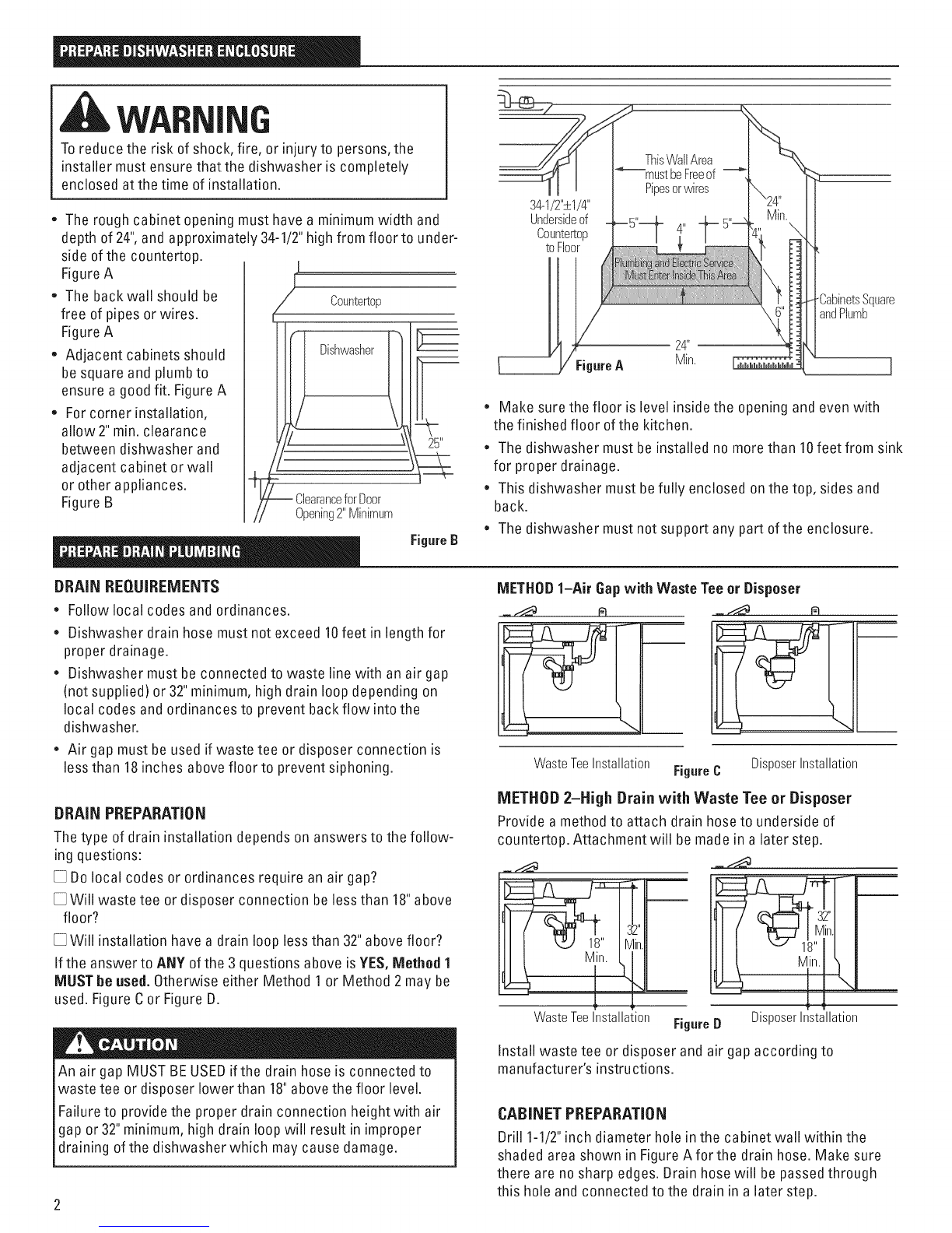
Step I_ Pre4est check Jist
[] Verifythat power isturnedoff at source.
[] Opendishwasher door and remove ailfoam and cardboard
packaging.
[] Removeliterature package with Owner's Manual.
[] Readthe Owner's Manual to familiarize yourself with the
operation ofthe dishwasher.
[] Add two quarts of water to the bottom ofthe dishwasher to
lubricate the pump seal.
[] Removethe protective film if present from the control
panel, access panel and door panel.
[] Checkto be surethat wiring issecure under the dish-
washer, and not pinched or in contact with door springs or
other dishwasher components.
[] Pull lower rack about halfway out. Checkto be sure it does
not roll back intodishwasher or further out. If it does, relevel
dishwasher.
[] Turn on water supply.
[] Checkfor plumbing leaks.Tighten connections if necessary.
[] Checkthat door spring does not contact water line,fill hose,
wiring or dishwasher components.
[] Turn onthe hot water faucet atthe sink andverify water
temperature. Water going to dishwasher must be between
the temperatures of 120°Fand 150°E
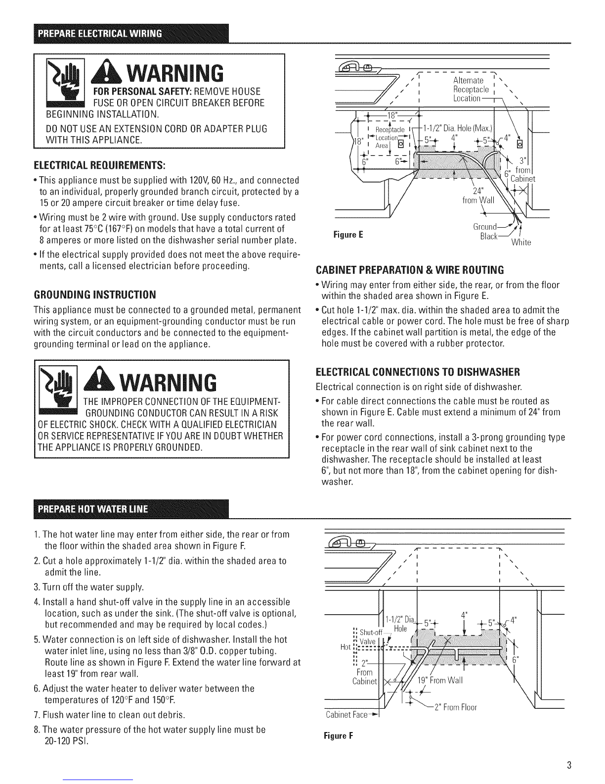
Step 17 Dishwasherwettest ]
[] Turn on power supply or if power cord is used, plug it into [] Checkfor leaks around the door.Aleak around the door
the wall outlet.
[] Latchdoor.
[] Select normal cycle on push-button or electronic models.
[] Ondial models,turn control dial just enough to start
dishwasher. Be careful notto turn the dial pastthe first
water fill. Onelectronic models, pushstart pad.
[] Checkto be surethat water enters the dishwasher. This
could take up to 4 minutes.
if water does not enter the dishwasher, checkto be sure
that water isturned on.
[] Checkfor leaks under the dishwasher, if a leak isfound,
turn off power supply,tighten connections and restore
power.
could be caused by dishwasher door rubbing or hitting
against adjacent cabinetry. Repositionthe dishwasher if
necessary.
[] The dishwasher will drain about 5 minutes after the first fill.
Checkdrain lines. If leaks are found, turn off power, correct
asnecessary and restore power.
[] Opendishwasher door and make sure most of the water has
drained. If not, checkthat disposer plug has been removed
and/or air gap is not plugged.
[] Letthe dishwasher run through anotherfill and drain cycle.
Checkagain to be sure there are no leaks.
[] Atthe end ofthe second drain, push the reset pad on
electronic models. Ondial models, unlatch the door and
rotate the dial to the "OFF"position.
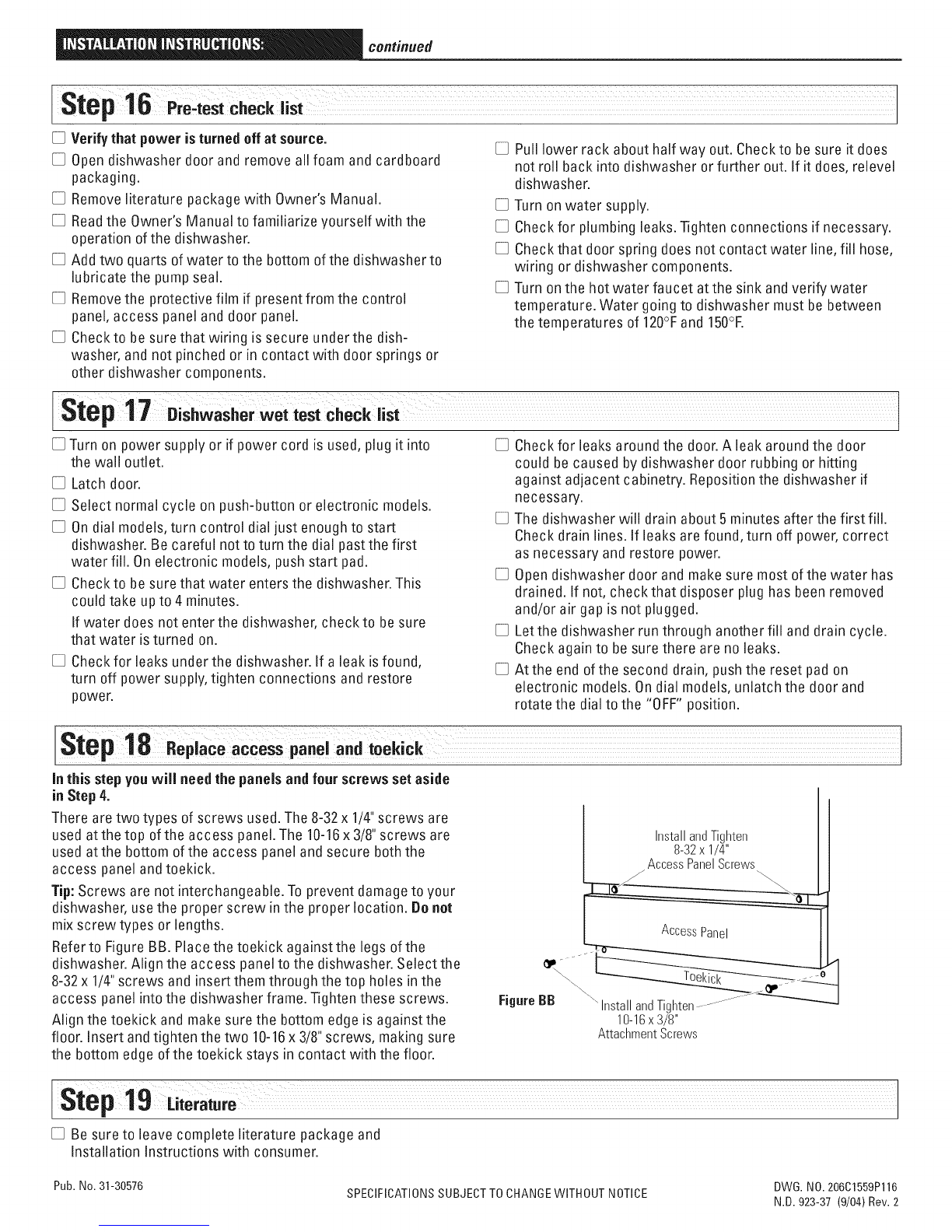
[Step18,o,,ooooooe,o.o,
in thisstepyouwiil needthe panelsand fourscrews setaside
in Step 4.
There are two types of screws used.The 8-32x 1/4"screws are
used atthe top ofthe access panel. The 10-16x 3/8"screws are
used atthe bottom ofthe access panel and secure both the
access panel andtoekick.
Tip: Screws are not interchangeable.To prevent damageto your
dishwasher, usethe proper screw in the proper location. Donot
mix screw types or lengths.
Refer to FigureBB. Place the toekick againstthe legs ofthe
dishwasher. Align the access panel to the dishwasher. Select the
8-32x 1/4"screws and insert them through the top holes inthe
access panel intothe dishwasher frame. Tighten these screws.
Align the toekick and make sure the bottom edge isagainst the
floor. Insert andtighten the two 10-16x 3/8"screws, making sure
the bottom edge of the toekick stays in contact with the floor.
InstallandTighten
8-32x 1/4"
AccessPanelScrews
AccessPanel
FigureBB "_"InstallandTighten.................
10-16x 3/8"
AttachmentScrews
[step ;or i°ro
[] Be sureto leave complete literature package and
Installation Instructions with consumer.
Pub. No.31-30576 DWG. NO. 206C1559P116
SPECIFICATIONSSUBJECTTOCHANGEWITHOUT NOTICE N.D. 923-37 (9/04) Rev. 2
This manual suits for next models
3
Table of contents
Other GE Dishwasher manuals

GE
GE Profile Triton XL PDW7000 Series User manual

GE
GE Profile PDW8100 Series User manual

GE
GE CDWT980VSS Manual

GE
GE GLD3806T Manual

GE
GE Appliances EDW3000 Series User manual

GE
GE GSD800 User manual

GE
GE GDT550HGD4WW User manual

GE
GE Spacemaker GSM603 User manual

GE
GE Profile PDW9800L Manual

GE
GE PDT660SSFSS User manual

GE
GE Appliances EDW3000 Series User manual

GE
GE GSM2130 User manual

GE
GE Monogram ZBD1850NII Manual

GE
GE GSC3500V User manual

GE
GE PDWF2 - Profile 24 in. Dishwasher User manual

GE
GE PDW7300N10WW User manual

GE
GE GSD1250 User manual

GE
GE GLDA696MSS User manual

GE
GE PDT145 Series User manual

GE
GE GSD1005 User manual