Printed in China 31-31573 04-16 GE
ADVERTENCIA:
• Retiretodoslos conductores decorrientedel electrodoméstico
de disyuntorode lacajadel fusible antesdecomenzar conla
instalación. Sinocumple conesto,sepodrá producir elriesgo
dedescargaseléctricas.
• Para reducirel riesgodedescargaeléctrica, incendioolesiones
a personas,elinstalador debeasegurarsede queellavaplatos
estécompletamente cerradoen elmomento dela instalación.
• La conexióninadecuadadel conductordeconexión atierra
del equipamientopuedeprovocarun riesgodedescarga
HOpFWULFD&RQVXOWHDXQHOHFWULFLVWDFDOL¿FDGRRUHSUHVHQWDQWH
deservicio técnicositiene dudassobrelacorrectaconexión
atierra delaparato.Si elcableadodoméstico nocuentacon
un cablede2 hilosconconexión atierra,un instaladordebe
realizarunaconexión atierra. Cuandoelcableado doméstico
es dealuminio,asegúresedeusar uncompuestoantioxidante
yconectoresde aluminioa cobreaprobadosporUL.
• Para reducirel riesgodedescargaeléctrica, incendioolesiones
a personas,elinstalador deberárealizaruncontrolpara
asegurar queloscables noesténpellizcados nidañados,que
HOFDEOHDGRGHOKRJDUHVWpFRQHFWDGRDOD¿FKDGHODFDMDGH
empalmes atravésde unamortiguador derefuerzo, yque
todas lasconexioneseléctricas realizadasen elmomentode la
instalación(tuercaspara cables)estén dentrode latapade la
cajade empalmes.
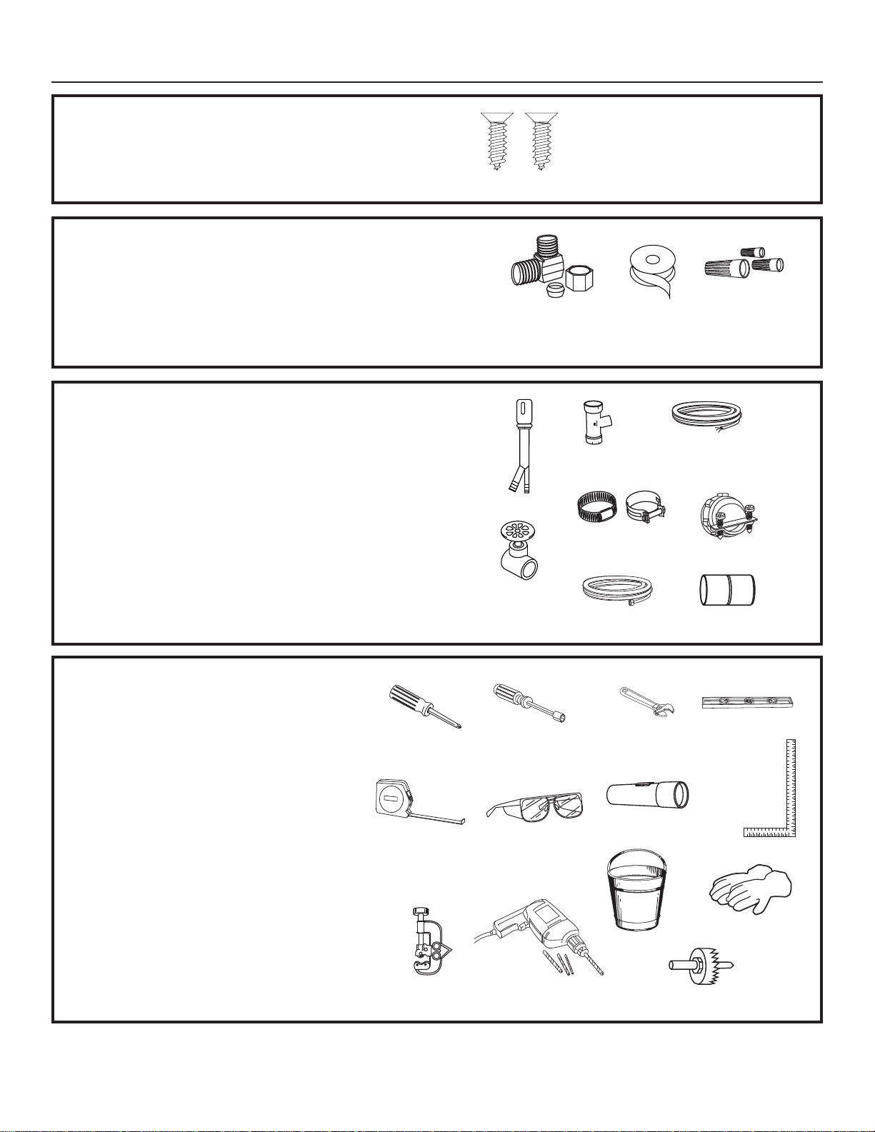
Installation Instructions
Built-In Dishwasher
If you have questions, call 800.GE.CARES (800.432.2737) or visit our Website at:
GEAppliances.com. In Canada, please call 800.561.3344 or visit www.geappliances.ca
READ CAREFULLY.
KEEP THESE INSTRUCTIONS.
FOR YOUR SAFETY
Read and observe all WARNINGS and CAUTIONS shown
throughout these instructions. While performing installations
described in this booklet, gloves, safety glasses or goggles
should be worn.
IMPORTANT –Observe all governing codes and
ordinances.
• Note to Installer – Be sure to leave these instructions for the
consumer’s and local inspector’s use.
• Note to Consumer – Keep these instructions with your
Owner’s Manual for future reference.
• Skill Level – Installation of this dishwasher requires
basic mechanical, electrical and plumbing skills. Proper
installation is the responsibility of the installer. Product
failure due to improper installation is not covered under
the GE Appliance Warranty. See warranty information.
• Completion Time – 1 to 3 Hours. New installations require
more time than replacement installations.
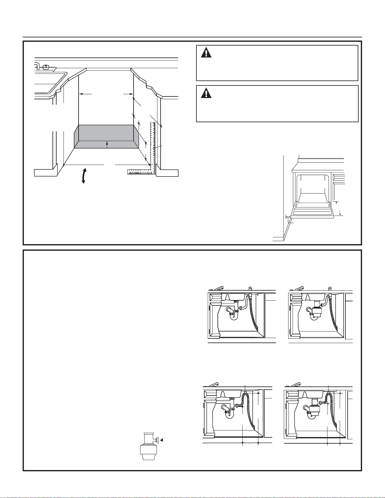
IMPORTANT –The dishwasher MUST be installed
to allow for future removal from the enclosure if service is
required.
Care should be exercised when the appliance is installed or
removed, to reduce the likelihood of damage to the power
supply cord.
If you received a damaged dishwasher, you should
immediately contact your dealer or builder.
Your dishwasher is a water heating appliance.
Optional Accessories – See the Owner’s Manual for available
custom panel kits.
BEFORE YOU BEGIN
Read these instructions completely and carefully.
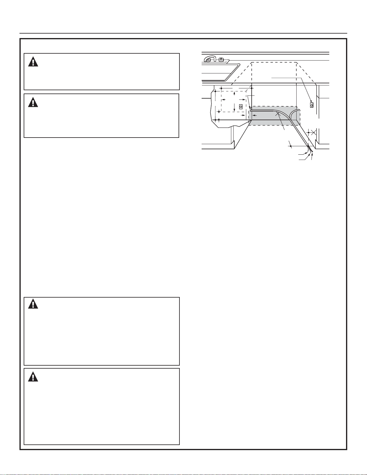
WARNING:
• Remove all power leading to the appliance from the circuit
breaker or fuse box before beginning installation. Failure
to do so can result in a risk of electrical shock.
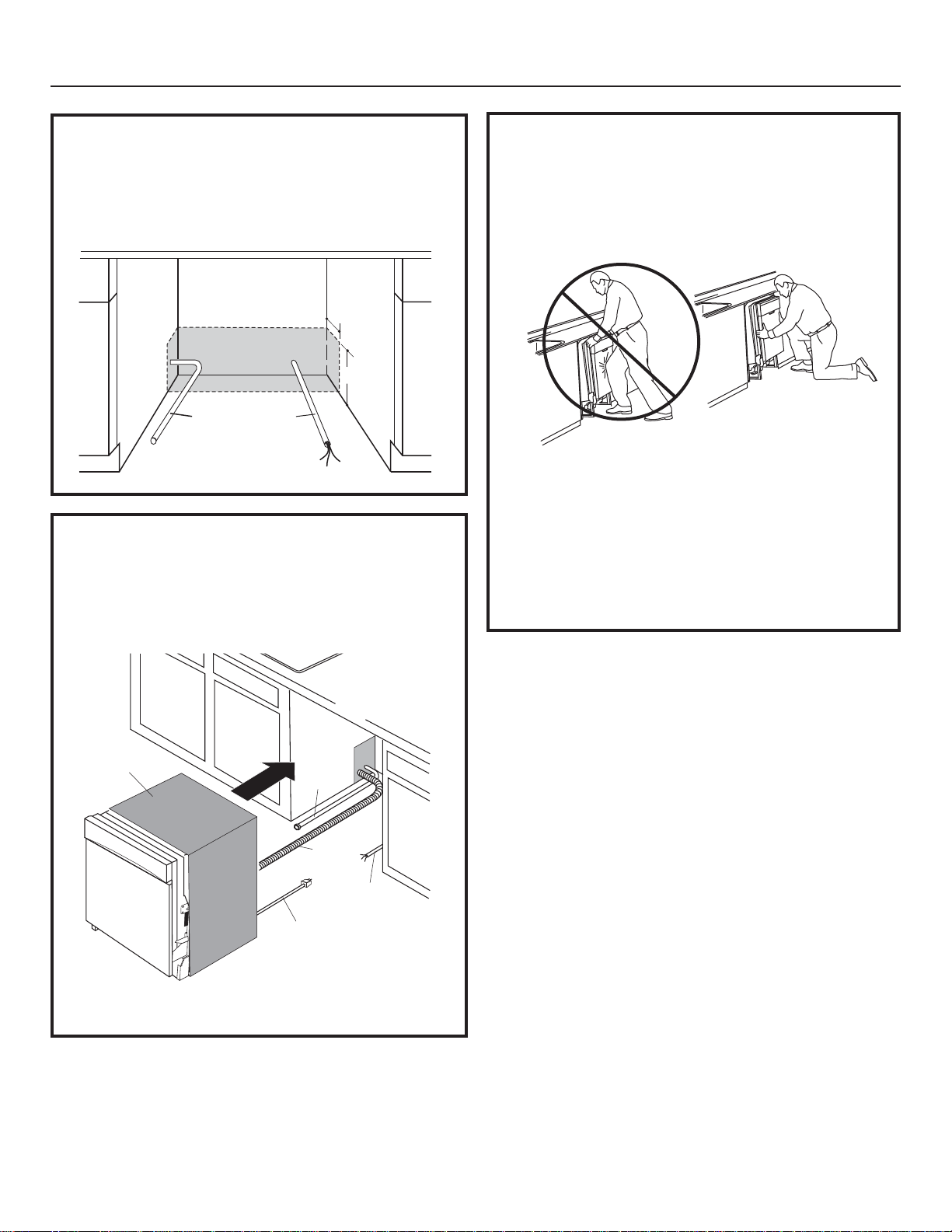
• 7RUHGXFHWKHULVNRIHOHFWULFVKRFN¿UHRULQMXU\WR
persons, the installer must ensure that the dishwasher is
completely enclosed at the time of installation.
• The improper connection of the equipment grounding
conductor can result in a risk of electric shock. Check
ZLWKDTXDOL¿HGHOHFWULFLDQRUVHUYLFHUHSUHVHQWDWLYHLI\RX
are in doubt that the appliance is properly grounded. If
house wiring is not 2-wire with ground, a ground must be
provided by the installer. When house wiring is aluminum,
be sure to use UL Listed anti-oxidant compound and
aluminum-to-copper connectors.
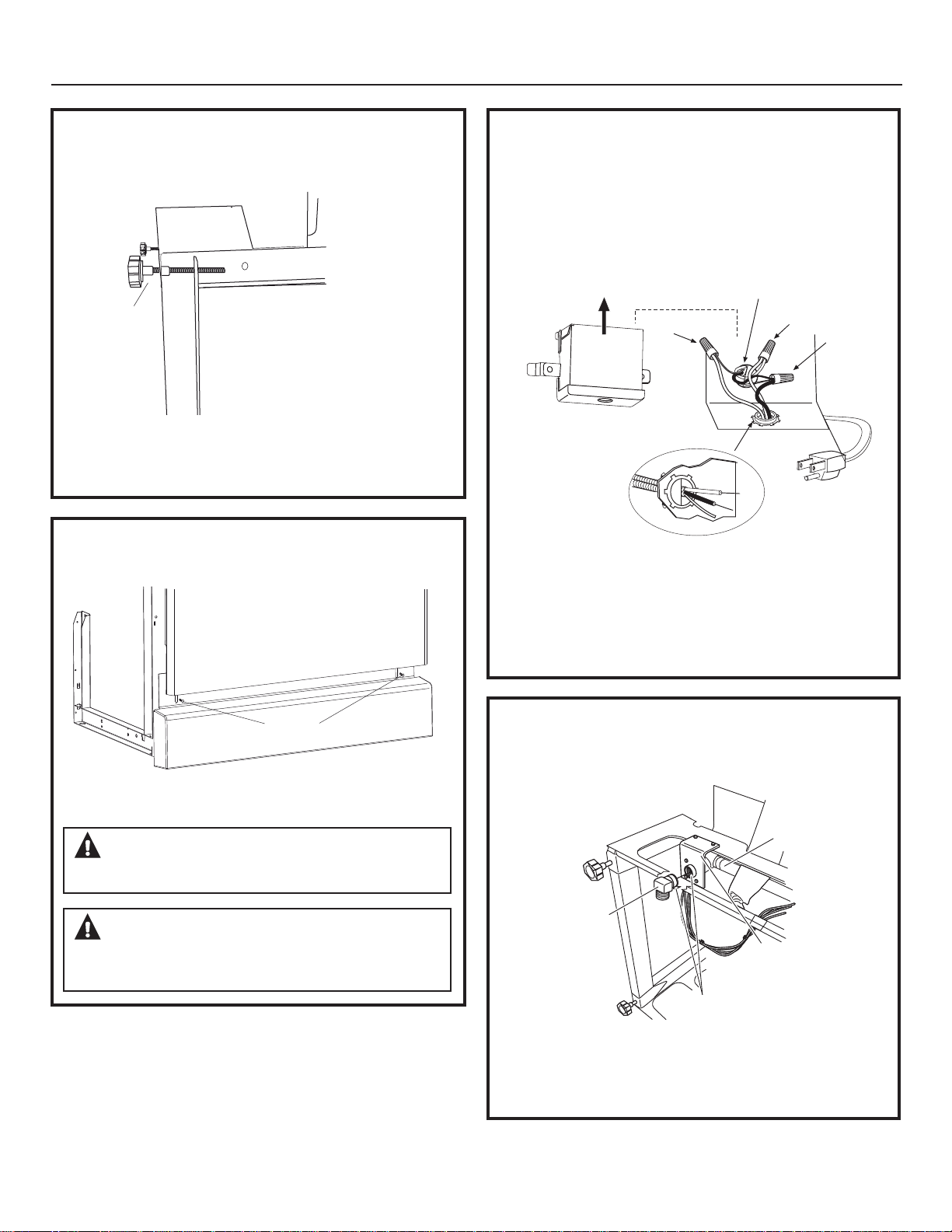
• 7RUHGXFHWKHULVNRIHOHFWULFVKRFN¿UHRULQMXU\WR
persons, the installer should check to ensure that wires
are not pinched or damaged, the house wiring is attached
to the junction box bracket through a strain relief, and all
electrical connections made at the time of install (wire
nuts) are contained inside of the junction box cover.