GE Monogram ZBD1800G User manual

If you have questions,call 800.626.2000 or visit our website at: www.monogram.com
Installation
Instructions
Built-In Dishwashers
ZBD1800G

Safety Information
2
CONTENTS
Installation Preparation
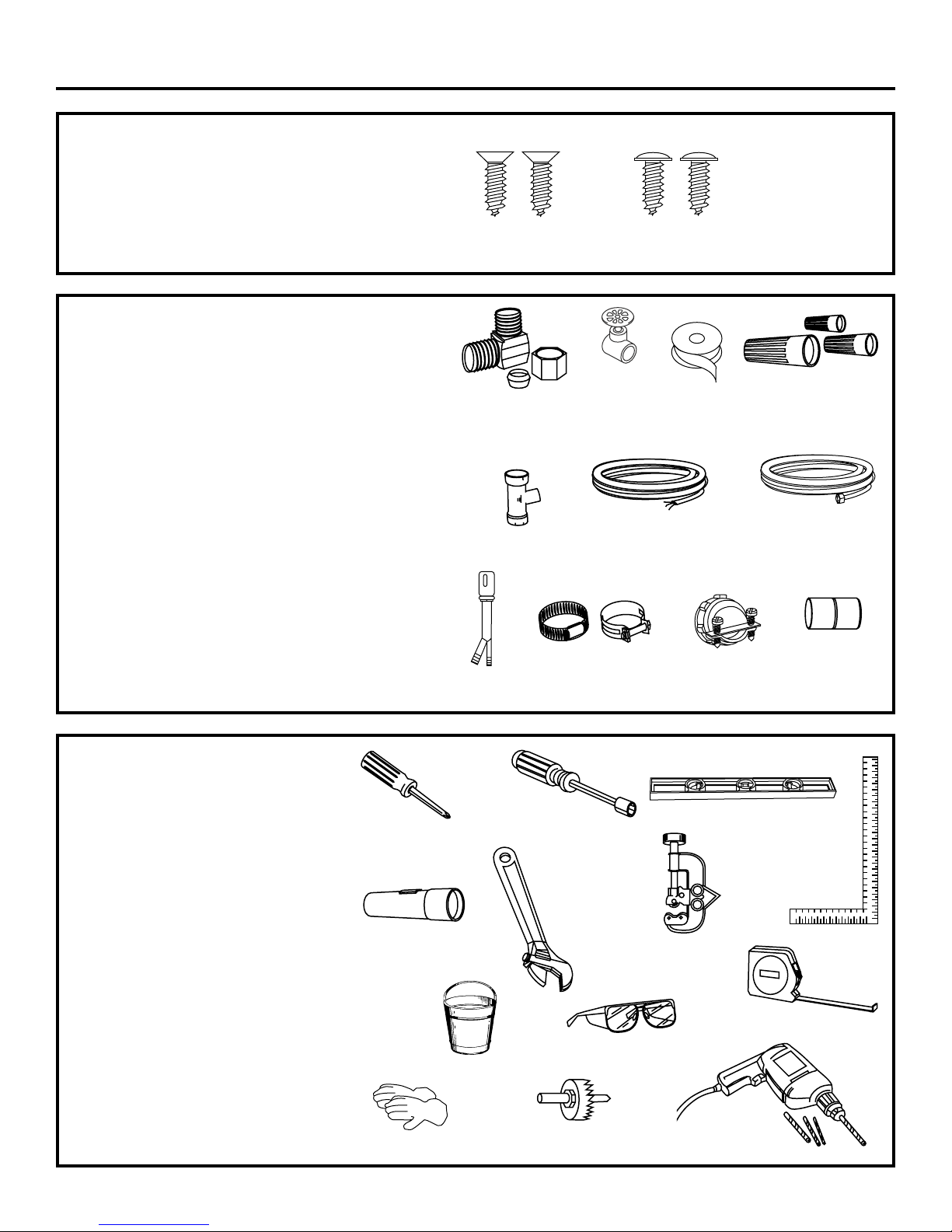
Parts Supplied ....................................................................3
Materials You Will Need ..................................................3
Tools You Will Need ..........................................................3
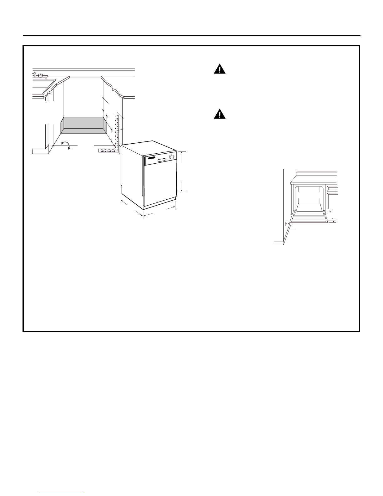
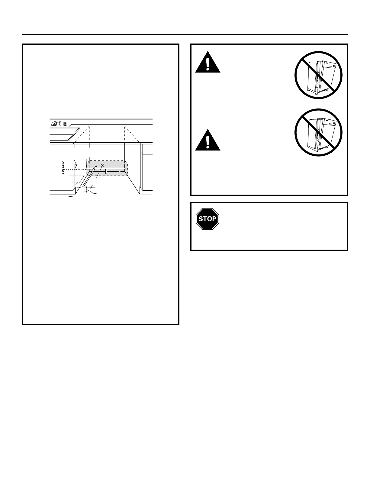
Prepare Dishwasher Enclosure ......................................4
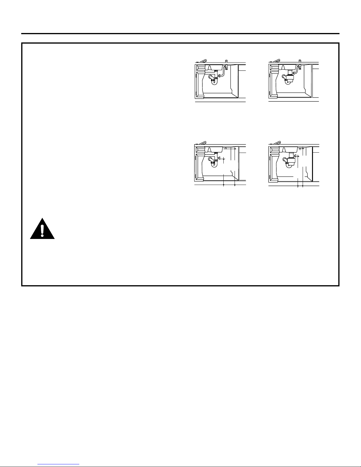
Drain Requirements ..........................................................5
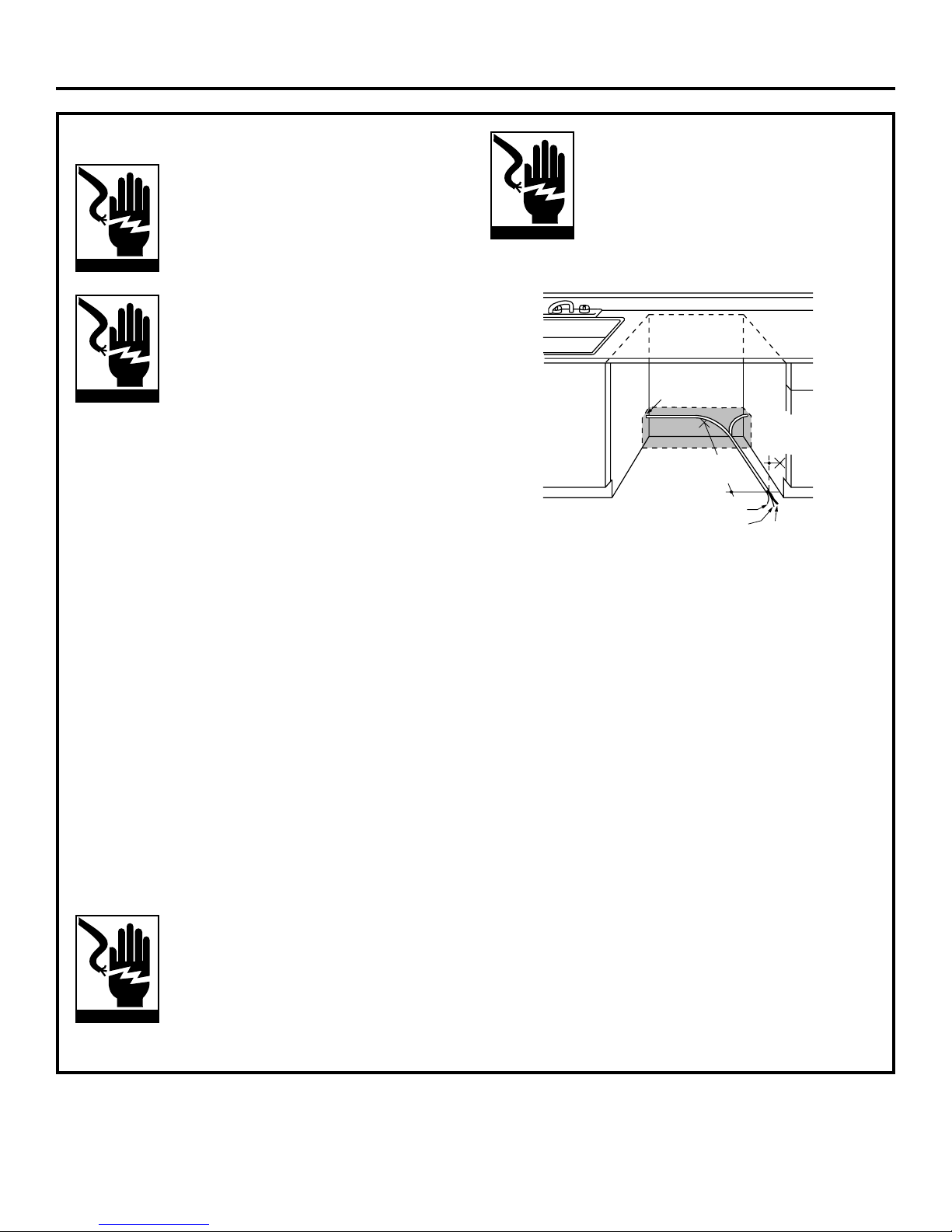
Prepare Electrical Wiring ................................................6
Prepare Hot Water Line....................................................7
Installation Instructions
Step 1, Check Door Balance............................................8
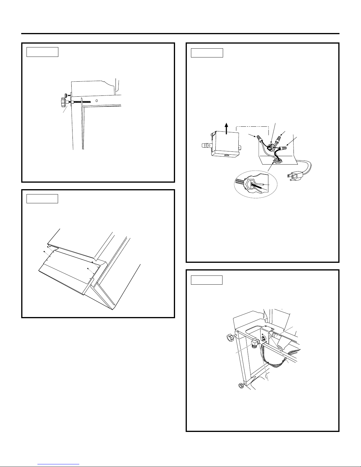
Step 1A, Adjust Door Springs ..........................................8
Step 2, Adjust Leveling Legs............................................9
Step 3, Remove ToeKick ..................................................9
Step 4, Install Power Cord................................................9
Step 5, Install 90° Elbow ..................................................9
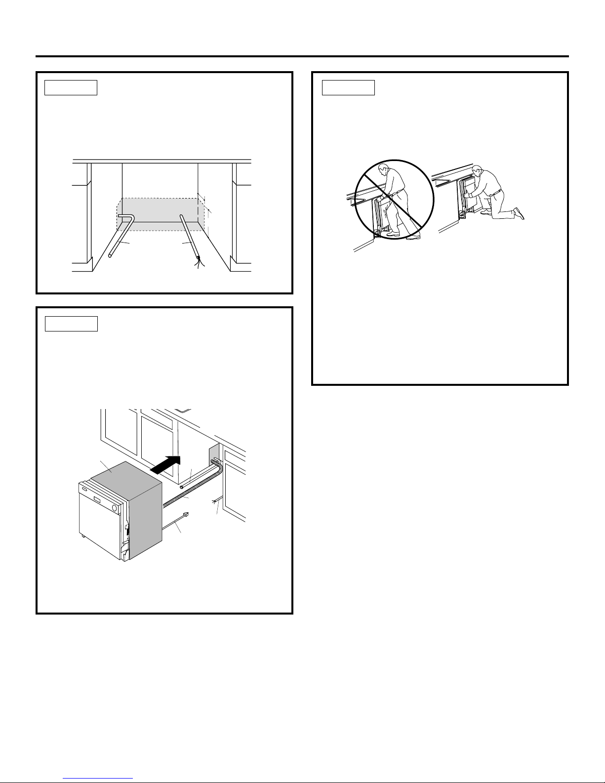
Step 6, Position Water Line and House Wiring ..........10
Step 7, Install Drain Hose Through Cabinet................10
Step 8, Slide Dishwasher Partially Into Cabinet ........10
Step 9, Position Dishwasher Under Countertop ........11
Step 10, Level Dishwasher ............................................11
Step 11, Secure Dishwasher To Cabinet ....................12
Step 12, Connect Water Supply ....................................12
Step 13, Connect Drain Line ..........................................13
Step 14, Connect Power Supply....................................14
Step 15, Pre-Test Checklist ............................................14
Step 16, Dishwasher Wet Test ......................................15
Step 17, Replace Toekick................................................15
Step 18, Literature............................................................15
BEFORE YOU BEGIN
Read these instructions completely and carefully.
• IMPORTANT —Save these instructions
for local inspector’s use. Observe all governing
codes and ordinances.
•Note to Installer —Be sure to leave these
instructions with the Consumer.
•Note to Consumer —Keep these instructions
with your Owner’s Manual for future reference.
•Skill Level —Installation of this dishwasher
requires basic mechanical and electrical skills.
Proper installation is the responsibility of the
installer. Product failure due to improper installation
is not covered under the GE Appliance Warranty.
•Completion Time —1 to 3 Hours.
New installations require more time than
replacement installations.
•IMPORTANT —The dishwasher MUST
be installed to allow for future removal from the
enclosure if service is required.
•If you received a damaged dishwasher, you should
immediately contact your dealer or builder.
READ CAREFULLY.
KEEP THESE INSTRUCTIONS.
FOR YOUR SAFETY
Read and observe all CAUTION and WARNINGS shown
throughout these instructions.
While performing installations described in this booklet,
gloves, safety glasses or goggles should be worn.
For Monogram local service in your area, 1.800.444.1845.
For Monogram service in Canada 1.888.880.3030
For Monogram Parts and Accessories, call 1.800.626.2002.

3
Installation Preparation
PARTS SUPPLIED:
Two #8 Phillips flat head wood screws, 5/8" long
to secure dishwasher to underside of countertop
(in literature package).
Two Phillips head, color matched toekick screws
(in literature package).
MATERIALS YOU WILL NEED:
Ferrule, compression nut and 90° Elbow (3/8"NPT external
thread on one end, opposite end sized to fit water supply)
Thread seal tape
UL Listed wire nuts (3)
Materials For New Installations Only:
Air gap for drain hose, if required
Waste tee for house plumbing, if applicable
Electrical cable or power cord, if applicable
Screw type hose clamps
Strain relief for electrical connection
Hand shut-off valve
Water line 3/8" min. copper
Coupler for extending drain line, if applicable
TOOLS YOU WILL NEED:
Phillips head screwdriver
5/16" and 1/4" nutdriver
6" Adjustable wrench
Level
Carpenters square
Measuring tape
Safety glasses
Flashlight
Bucket to catch water when flushing the line
Gloves
For New Installations Only:
Tubing cutter
Drill and appropriate bits
Hole saw set
90° Elbow,
Ferrule and
Compression Nut
Wire Nuts (3)
Waste Tee
Electrical Cable
(or Power Cord, if applicable)
Hot Water line
Screw Type
Hose Clamps
Coupler
Hand
Shut-Off
Valve
2 Wood Screws
Hole Saw Set
Measuring Tape
Tubing Cutter
Drill and Bits
Phillips
Head
Screwdriver
1/4" and 5/16"
Nutdriver
Safety Glasses
6" Adjustable
Wrench
Bucket
Flashlight
Gloves
Carpenters
Square
Level
Thread
Seal Tape
Air Gap
Strain Relief
2 Color Matched
Toekick Screws

4
Installation Preparation
PREPARE DISHWASHER ENCLOSURE
• The rough cabinet opening must be at least 24" deep
and 17-5/8" to 18" wide. The opening should be 34"
to 35" max. height.
• Plumbing and electrical service must enter the
shaded area.
• The dishwasher must be installed so that drain hose
is no more than 10 feet in length for proper drainage.
• The dishwasher must be fully enclosed on the top,
sides and back, and must not support any part of
the enclosure.
• These dishwashers may be installed beneath
countertops of stone or other materials that
will not accept screws. No trim kit required.
CLEARANCES: When
installed into a corner,
allow 2" min. clearance
between dishwasher and
adjacent cabinet, wall or
other appliances. Allow
25-5/8" min. clearance
from the front of the
dishwasher for door
opening. Figure B
Figure A
Figure B
4
6
Cabinets
Square
and
Plumb
Floor MUST
be Even with
Room Floor.
34" to 35"
Underside of
Countertop
to Floor
24"
Min.
17-5/8" Min.
18" Max.
17-1/2"
22-1/2" Max.
32-1/2"
Adjustable
to 35"
Clearance for Door
Opening 2" Minimum
Countertop
Dishwasher
25-5/8"
NOTE: ADA installation, (32-1/2") beneath 34" high
countertops may be accomplished by adjusting the
toekick and leveling legs.
WARNING
To reduce the risk of electric shock, fire, or injury
to persons, the installer must ensure that the
dishwasher is completely enclosed at the time
of installation.
ATTENTION
Pour réduire le risque de choc électrique,
d’incendie ou de blessures, l’installateur doit
s’assurer, au moment de l’installation, que le
lave-vaisselle est complètement enclos.

5
DRAIN REQUIREMENTS
• Follow local codes and ordinances.
• Do not exceed 10 feet distance to drain.
• Do not connect drain lines from other devices
to the dishwasher drain hose.
• Dishwasher must be connected to waste line with an
air gap (not supplied) or 32" minimum high drain loop,
depending on local codes and ordinances to prevent
back flow into the dishwasher.
• Air gap must be used if waste tee or disposer
connection is less than 18" above the floor to prevent
siphoning.
DRAIN PREPARATION
The type of drain installation depends on answers to
the following questions:
Do local codes or ordinances require an air gap?
Will waste tee or disposer connection be less than
18" above the floor?
Will installation have a drain loop less than 32"
above floor?
If the answer to ANY of the 3 questions above is YES,
Method 1 MUST be used. Otherwise either Method 1
or Method 2 may be used. Figure C or Figure D.
CAUTION:
An air gap MUST BE USED if the drain hose
is connected to waste tee or disposer lower than 18"
above the floor.
Failure to provide the proper drain connection height
with air gap or 32" minimum, high drain loop will result
in improper draining of the dishwasher.
Figure C
Figure D
18"
Min.
32"
Min.
32"
Min.
18"
Min.
Install waste tee or disposer and air gap according to
manufacturer’s instructions.
CABINET PREPARATION
• Drill a 1-1/2" dia. hole in the cabinet wall within the
shaded areas shown in Figure A for the drain hose
connection. The hole should be smooth with no
sharp edges.
Method 1 –Air Gap with Waste Tee or Disposer
Method 2 –High Drain with Waste Tee or Disposer
Provide a method to attach drain hose to underside
of countertop.
Installation Preparation

6
Installation Preparation
Cabinet Preparation & Wire Routing
• The wiring may enter the opening from either side,
rear or the floor within the shaded area.
• Cut a 1-1/2" max. dia. hole to admit the electrical cable.
The hole must be free of sharp edges. If the cabinet
wall is metal, the hole edge must be covered with a
bushing.
• Cable direct connections may pass through the
same hole as the drain hose and hot water line, if
convenient. If cabinet wall is metal, the hole edge must
be covered with a bushing. NOTE: Power cords with
plug must pass through a separate hole.
Electrical Connection to Dishwasher
Electrical connection is on the right front of dishwasher.
• For cable direct connections the cable must be routed
as shown in Figure E. Cable must extend a minimum of
24" from the rear wall.
• For power cord connections, install a 3-prong
grounding type receptacle. The power-supply
receptacle for the appliance shall be installed in a
cabinet or on a wall adjacent to the undercounter
space in which the appliance is to be installed.
Figure E
WARNING
FOR PERSONAL SAFETY: Remove house
fuse or open circuit breaker before
beginning installation. Do not use an
extension cord or adapter plug with
this appliance.
ATTENTION
SÉCURITÉ: Enlever le fusible du circuit
ou déclencher le disjoncteur avant de
commencer l’installation. Avec cet
appareil, ne pas utiliser une rallonge
ou un adaptateur de prise.
PREPARE ELECTRICAL WIRING
Electrical Requirements
• This appliance must be supplied with 120V, 60 Hz., and
connected to an individual properly grounded branch
circuit, protected by a 15 or 20 ampere circuit breaker
or time delay fuse.
• Wiring must be 2 wire with ground.
• If the electrical supply does not meet the above
requirements, call a licensed electrician before
proceeding.
Grounding Instructions –Cable Direct
This appliance must be connected to a grounded metal,
permanent wiring system, or an equipment grounding
conductor must be run with the circuit conductors and
be connected to the equipment grounding terminal or
lead on the appliance.
Grounding Instructions –Power Cord Models
This appliance must be grounded. In the event of a
malfunction or breakdown, grounding will reduce the
risk of electrical shock by providing a path of least
resistance for electric current. The plug must be
plugged into an appropriate outlet that is installed
and grounded in accordance with local codes and
ordinances.
WARNING
The improper connection of the
equipment grounding conductor can
result in a risk of electric shock. Check
with a qualified electrician or service
representative if you are in doubt that
the appliance is properly grounded.
White
24"
from Wall
3"
from
Cabinet
Ground
Black
1-1/2" Dia.
Hole (Max.)
ATTENTION
Le mauvais branchement du conducteur
de mise à la terre peut causer des risques
de choc électrique. En cas de doute sur
la mise à la terre de l’appareil, consulter
un électricien agrée ou un technicien de
réparation.

7
Installation Instructions
PREPARE HOT WATER LINE
• The line may enter from either side, rear or floor
within the shaded area shown in Figure F.
• The line may pass through the same hole as the
electrical cable and drain hose. Or, cut an additional
1-1/2" dia. hole to accommodate the water line.
If power cord with plug is used, water line must not
pass through power cord hole.
Figure F
Water Line Connection
• Turn off the water supply.
• Install a hand shut-off valve in an accessible location,
such as under the sink. (Optional, but strongly
recommended and may be required by local codes.)
• Water connection is on the left side of the
dishwasher. Install the hot water inlet line, using
no less than 3/8" O.D. copper tubing. Route the line
as shown in Figure F and extend forward at least
18" from rear wall.
• Adjust water heater for 120°F to 150°F temperature.
• Flush water line to clean out debris.
• The hot water supply line pressure must be
20-120 PSI.
CAUTION:
Opening the door will
cause the dishwasher to
tip forward. Do not open the door
until you are ready to install the
dishwasher. If it is necessary to
open the door, hold the top of the
dishwasher securely with one
hand and hold the door with the
other hand.
ATTENTION :
Quand vous ouvrez la
porte, cela fait basculer
vers l’avant le lave-vaisselle.
N’ouvrez jamais la porte avant d’être prêt àinstaller
le lave-vaisselle. Si vous devez ouvrir la porte,
tenez fort le haut du lave-vaisselle avec une main
en ouvrant la porte avec l’autre.
Cabinet Face
Shut-off
Valve
3" From Floor
18" From Wall
4"
From
Cabinet
1-1/2" Dia.
Hole
Hot
BEFORE YOU BEGIN
Locate and set aside the package containing
2 Phillips head countertop mounting screws
and 2 additional toekick screws (located in
the literature package).

STEP 1A ADJUST DOOR SPRINGS
(IF NECESSARY)
To adjust the door springs, you will need to remove the dishwasher
side panels.
To remove the side panels:
• Remove the screws from the top and back of each dishwasher
side panel, sixteen screws total. Open the door and remove the
four screws securing the panels to the inside door frame.
• Lay the dishwasher on its back. Remove the four screws
securing the toekick to the dishwasher, and remove the toekick.
• Remove the single screw just above and to the side of each front
leveling leg.
• Remove the side panels and set the dishwasher upright.
To adjust the door springs:
• Pull the spring adjustment pin out of the holes, insert in the next
highest or lowest hole and test again.
• Adjust both door springs to the same tension.
• Continue moving the spring pin until door is balanced.
• Replace the dishwasher side panels and proceed to Step 2.
Screws
Screws
Screws
Toekick
8
Installation Instructions
STEP 1 CHECK DOOR BALANCE
• To check the door balance, hold the top of the dishwasher firmly.
• Open the door slowly. If the door drops when released,
you will need to increase spring tension. If the door closes
when released, you will need to decrease tension.
• If adjustments are needed, see Step 1A. If no adjustments are
needed, skip to Step 2.
Increase
Decrease
Screws
Screws Screws
Front Rear
Screw
Screw
Figure G Figure H
Figure I
Figure J
Figure K

9
White
Ground Black
Check That White, Black and
Green Dishwasher Wires Are Threaded
Thru Hole in Back
Remove
Junction Box
Cover
Insert Power
Cord Wires Thru
Strain Relief
and Tighten
Use UL Listed
Wire Nuts
A
C
B
D
• Do not over tighten 90° elbow, water valve bracket
could bend or water valve fitting could break.
• Position the end of the elbow to face the rear of the
dishwasher.
STEP 5 INSTALL 90° ELBOW
• Wrap 90° elbow with thread seal tape.
• Install a 90° elbow onto the water valve.
Figure O
Figure M
STEP 3 REMOVE TOEKICK
• Remove the 4 toekick screws. Lift off the 2-piece
toekick.
• Measure installation height and dishwasher height.
Extend leveling legs out from the dishwasher base,
1/4" less than installation height.
Figure L
STEP 2 ADJUST LEVELING LEGS
• Move the dishwasher close to the installation
location and lay it on its back.
• Connect incoming power cord white (or ribbed)
to dishwasher white, black (or smooth) to black and
ground to dishwasher green wire. Use UL listed wire
nuts of appropriate size.
• Replace junction box cover. Be sure wires are not
pinched under the cover.
STEP 4 INSTALL POWER CORD
Skip this step if dishwasher will be direct wired.
The power cord and connections must comply with
the National Electrical Code, Section 422 and/or local
codes and ordinances.
• Recommended power cord length is 54" min. and
64" max.
Figure N
Adjust to
Installation
Height
Remove
4 Toekick
Screws
90°
Elbow
Fill
Hose
Thread
Seal Tape
Water
Valve
Bracket
Installation Instructions

Do Not Push Against
Front Door Panel With
Knee. Damage to The
Door Panel Will Occur.
Reposition Dishwasher
by Grasping Both Sides
With Hands.
Water
Line
House
Wiring
4"
6"
10
STEP 8 SLIDE DISHWASHER
PARTIALLY INTO CABINET
DO NOT PUSH AGAINST FRONT PANEL WITH KNEES.
DAMAGE WILL OCCUR.
• Slide dishwasher into the opening a few inches at
a time.
• As you proceed, pull the drain hose through the
opening under the sink. Stop pushing when the
dishwasher is a few inches forward of adjacent
cabinetry.
• Make sure drain hose is not kinked under the
dishwasher and there is no interference with the
water line and wiring or any other component.
Figure R
TIP: Position water line and house wiring on the
floor to avoid interference with base of dishwasher.
Figure Q
STEP 7 INSERT DRAIN HOSE
THROUGH CABINET
• Upright the dishwasher and position in front of the
opening. Insert drain hose into cabinet wall hole.
If a power cord is used, guide the end through a
separate hole.
STEP 6 POSITION WATER LINE
AND HOUSE WIRING
• Position water supply line and house wiring on the
floor of the opening to avoid interference with base
of dishwasher and components under dishwasher.
Figure P
Power Cord
(If Used)
Insulation
Blanket Water
Line
House
Wiring
Drain
Hose
Maximum
Drain Hose
Length 10'
Installation Instructions

11
STEP 9 POSITION DISHWASHER UNDER COUNTERTOP
• Check to be sure that wires are secure under the
dishwasher and not pinched or in contact with door
springs or other dishwasher components.
• Push dishwasher into cabinet. The front corners of the
dishwasher door should be flush with cabinet doors.
Be careful not to dent front panel with knees or
damage countertop or cabinets with dishwasher
parts.
• Carefully open and close the door to ensure that the
door panel does not catch or rub on the cabinet frame.
• If the door catches or rubs on the frame, reposition
and/or level the unit (see Step 10) until the door moves
freely and does not contact the cabinet frame.
NOTE: If the drain hose gets trapped between the
wall and the back side of the dishwasher, it can prevent
the dishwasher from sliding all the way back into the
cabinet opening, and thus preventing a flush fit with
the kitchen cabinet panels.
NOTE: If this dishwasher is replacing an existing
dishwasher, the old countertop bracket screw holes
may not be in the correct position. New holes may be
required.
Figure S
Figure T
STEP 10 LEVEL DISHWASHER
IMPORTANT –Dishwasher must
be level for proper dish rack operation and wash
performance.
TIP: Pull lower rack out, about halfway. Check to be sure
the rack does not roll forward or back into dishwasher.
If the rack rolls in either direction, the dishwasher must
be leveled again.
• If door hits the tub, the dishwasher is not installed
correctly. Adjust leveling legs to align door to tub.
• Level the dishwasher
by adjusting the
four leveling legs
individually.
Figure U
• Place level on
door and rack
track inside the
tub as shown to
check that the
dishwasher is
level.
Turn Legs
to Adjust
Do Not Push Against
Front Door Panel With
Knee. Damage to The
Door Panel Will Occur.
Reposition Dishwasher
by Grasping Both
Sides With Hands
Check
Level
Side
To Side
Check
Level
Front
to Back
Installation Instructions

12
The dishwasher must be secured to the countertop
or the cabinet sides. When countertops are made of
wood, use Method 1. When countertops are granite
or other materials that will not accept screws, use
Method 2 to secure dishwasher at the sides.
NOTE: If desired, drill pilot holes through the
dishwasher holes before inserting screws to minimize
the possibility of damage to cabinets or countertop.
IMPORTANT –Check to be sure
the dishwasher is centered in the opening and there is
no interference with adjacent cabinets when opening
or closing the door.
Method 1 –Secure dishwasher to wood countertop:
• Fasten the dishwasher to the underside of the
countertop with the 2 Phillips wood screws provided.
Figure X
STEP 11 SECURE DISHWASHER STEP 12 CONNECT WATER SUPPLY
Connect water supply line to 90° elbow.
• Slide compression nut, then ferrule over end of
water line.
• Insert water line into 90° elbow.
• Slide ferrule against elbow and secure with
compression nut.
Ferrule
90° Elbow
Compression Nut
Hot Water
Supply Line
IMPORTANT –Check to be sure
that door spring does not rub or contact the fill hose
or water supply line. Test by opening and closing
the door. Re-route the lines if a rubbing noise or
interference occurs.
Method 2 –Secure dishwasher with side mounting
brackets:
• Remove plug buttons (one on each side).
• Install screw through the hole in the side of the
dishwasher and into the adjacent cabinet. Reinstall
plug buttons.
IMPORTANT –Drive screws
straight and flush. Protruding screw heads will
scratch the top of the control panel and can
interfere with door closing.
Plug
Buttons
Figure V
Figure W
Installation Instructions

13
• If a longer drain hose is required, add up to 42" of
length for a total of 10 ft. to the factory installed hose.
Use 5/8" or 7/8" inside diameter hose and a coupler to
connect the two hose ends. Secure the connection
with hose clamps.
Figure Y
STEP 13 CONNECT DRAIN LINE
FOLLOW ALL LOCAL CODES AND ORDINANCES.
The drain hose molded end will fit 5/8", 3/4" or 1"
diameter connections on the air gap, waste tee or
disposer. Cut on the marked line as required for
your installation.
DRAIN LINE INSTALLATION
• Connect drain line to air gap, waste tee or disposer
using either previously determined method.
Waste Tee Installation
Method 1 – Air gap with waste tee or disposer
Disposer Installation
Method 2 – High drain loop with waste tee or disposer
Disposer Installation
Figure AA
Figure BB
• Secure the drain hose to the air gap, waste tee or
disposer with clamps.
NOTE: TOTAL DRAIN HOSE LENGTH MUST NOT EXCEED
10 FEET FOR PROPER DRAIN OPERATION.
IMPORTANT –
When connecting drain line to
disposer, check to be sure that drain plug has been
removed. DISHWASHER WILL NOT DRAIN IF PLUG IS
LEFT IN PLACE.
TIP: Avoid unnecessary service call charges. Always
be sure disposer drain plug has been removed before
attaching dishwasher drain hose to the disposer.
Figure Z
Remove
Hopper
Plug
Cutting Lines
1" 3/4" 5/8"
IMPORTANT: Do not cut corrugated
portion of hose
Hose Clamp
Coupler Hose Clamp
Fasten to underside
of countertop
32"
Min.
18"
Min.
Fasten to underside
of countertop
18"
Min.
Waste Tee Installation
Installation Instructions

14
Figure CC
STEP 15 PRE-TEST CHECKLIST
Review this list after installing your dishwasher to
avoid charges for a service call that is not covered
by your warranty.
Check to be sure power is OFF.
Open door and remove all foam and paper
packaging.
Locate the Owner’s Manual in the literature
package.
Read the Owner’s Manual for operating
instructions.
Check door opening and closing. If door does not
open and close freely or tends to fall, check spring
adjustments. See Step 1.
Check to be sure that wiring is secure under the
dishwasher, not pinched or in contact with door
springs or other components. See Step 9.
Check door alignment with tub. If door hits tub,
level dishwasher. See Step 10.
Pull lower rack out, about half way. Check to be
sure it does not roll back or forward on the door.
If the rack moves, adjust leveling legs.
See Step 10.
Check door alignment with cabinet. If door hits
cabinet, reposition or relevel dishwasher. See
Step 10.
Verify water supply and drain lines are not kinked
or in contact with other components. Contact with
motor or dishwasher frame could cause noise.
See Step 8.
Turn on the sink hot water faucet and verify
water temperature. Incoming water temperature
must be between 120°F and 150°F. A minimum of
120°F temperature is required for best wash
performance. See “Prepare Hot Water Line,”
page 7.
Add 2 quarts of water to the bottom of the
dishwasher to lubricate the pump seal.
Turn on water supply. Check for leaks. Tighten
connections if needed.
Remove protective film if present from the control
panel and door.
STEP 14 CONNECT POWER
SUPPLY
Skip this step if equipped with power cord.
Verify that power is turned off at the source.
• Remove junction box cover “A”.
• Locate the three dishwasher wires, (white, black
and green) with stripped ends. Insert dishwasher
wires through the small hole in the junction box “B”.
• Secure house wiring to the bottom of the junction
box with a strain relief “C”.
• Use wire nuts to connect incoming ground to green,
white to white and black to black “D”.
• Replace junction box cover “E”. Check to be sure
that wires are not pinched under the cover.
WARNING
If house wiring is not 2-wire with
ground, a ground must be provided
by the installer. When house wiring
is aluminum, be sure to use UL Listed
anti-oxidant compound and aluminum-
to-copper connectors.
ATTENTION
Si le circuit de la maison n’est pas
un circuit à deux fils plus fil de terre,
l’installateur doit installer un fil de
terre. Quand le circuit de la maison
est en aluminium, il faut prendre soin
d’utiliser une pâte antioxydante et des
connecteurs aluminium à cuivre sur la
liste UL.
White
Ground Black
Check That White, Black and
Green Dishwasher Wires Are Threaded
Thru Hole in Back
Remove
Junction Box
Cover
Insert Power
Cord Wires Thru
Strain Relief
and Tighten
Use UL Listed
Wire Nuts
A
C
B
D
E. Replace Junction Box Cover
Installation Instructions

15
2-Piece Toekick
Adjust Up
or Down
Use Top 4
Screw Holes
Use Additional 2 Screws
for Installations Over 33-1/2" High
• Place 2-piece toekick against the legs of the
dishwasher.
• Place the inner toekick piece (with slots) against
the toekick bracket. The slots should align with
toekick bracket screw holes. Allow the toekick
to touch the floor.
• Place larger toekick over the inner piece and
install 4 toekick screws.
• Use additional 2 screws for installations over
33-1/2" high.
• Use both toekick pieces for all installation heights.
Figure DD
STEP 17 REPLACE TOEKICK
STEP 16 DISHWASHER WET TEST
Turn on power supply (or plug power cord into
outlet, if equipped).
Turn dial to Normal “Wash” position.
Close door.
Check to be sure that water enters the dishwasher.
If water does not enter the dishwasher, check to
be sure that water and power are turned on.
Check for leaks under the dishwasher. If a leak
is found, turn power supply off, then tighten
connections. Restore power after leak is corrected.
Check for leaks around the door. A leak around the
door could be caused by door rubbing or hitting
against adjacent cabinetry. Reposition the
dishwasher if necessary. See Step 9.
The dishwasher will drain and turn off about 5 to 7
minutes after the first fill. Check drain lines. If leaks
are found, turn power off at the breaker and correct
plumbing as necessary. Restore power after
corrections are made. See Step 12.
Open dishwasher door and make sure most of the
water has drained. If not, check that disposer plug
has been removed and/or air gap is not plugged.
See Step 12. Also check drain line for kinking.
Run the dishwasher through another fill and drain
cycle. Check for leaks and correct if required.
At the end of drain, open door and turn dial to
OFF position.
STEP 18 LITERATURE
Be sure to leave complete literature package and
installation instructions with consumer.
Installation Instructions

Pub. No. 31-30571
Part No. 206C1559P111
02-04 JR
Printed in China
NOTE: While performing installations described in this book,
safety glasses or goggles should be worn.
For Monogram®local service in your area, call
1.800.444.1845.
NOTE: Product improvement is a continuing endeavor
at General Electric. Therefore, materials, appearance
and specifications are subject to change without notice.
Table of contents
Other GE Dishwasher manuals

GE
GE Appliances GSC3200 User manual

GE
GE GSD2800L-20 User manual

GE
GE Triton XL GSD6900 Series User manual

GE
GE Profile PDW8900 Series User manual

GE
GE CleanDesign GSD400T User manual

GE
GE Monogram ZBD4900YSS User instructions

GE
GE GSD800 User manual

GE
GE Nautilus GHD3500 Series, GSD34 User manual

GE
GE GSM18 - Appliances 18 in. Dishwasher User manual

GE
GE GE Profile PDW7800P Manual