GE Monogram ZBD1800K Series How to use

– 1 –
MODEL SERIES:
ZBD1800K
Monogram 18-In. Built-In
Compact Dishwasher
GE Consumer & Industrial
TECHNICALSERVICE GUIDE
PUB # 31-9123 7/04

– 2 –
IMPORTANT SAFETY NOTICE
The information in this service guide is intended for use by
individuals possessing adequate backgrounds of electrical,
electronic, and mechanical experience. Any attempt to repair a
major appliance may result in personal injury and property
damage. The manufacturer or seller cannot be responsible for the
interpretation of this information, nor can it assume any liability in
connection with its use.
WARNING
To avoid personal injury, disconnect power before servicing this
product. If electrical power is required for diagnosis or test
purposes, disconnect the power immediately after performing the
necessary checks.
RECONNECT ALL GROUNDING DEVICES
If grounding wires, screws, straps, clips, nuts, or washers used
to complete a path to ground are removed for service, they must
be returned to their original position and properly fastened.
GE Consumer & Industrial
Technical Service Guide
Copyright © 2004
All rights reserved. This service guide may not be reproduced in whole or in part,`
in any form, without written permission from the General Electric Company.

– 3 –
TABLE OF CONTENTS
Bottom Door Seal.................................................................................................19
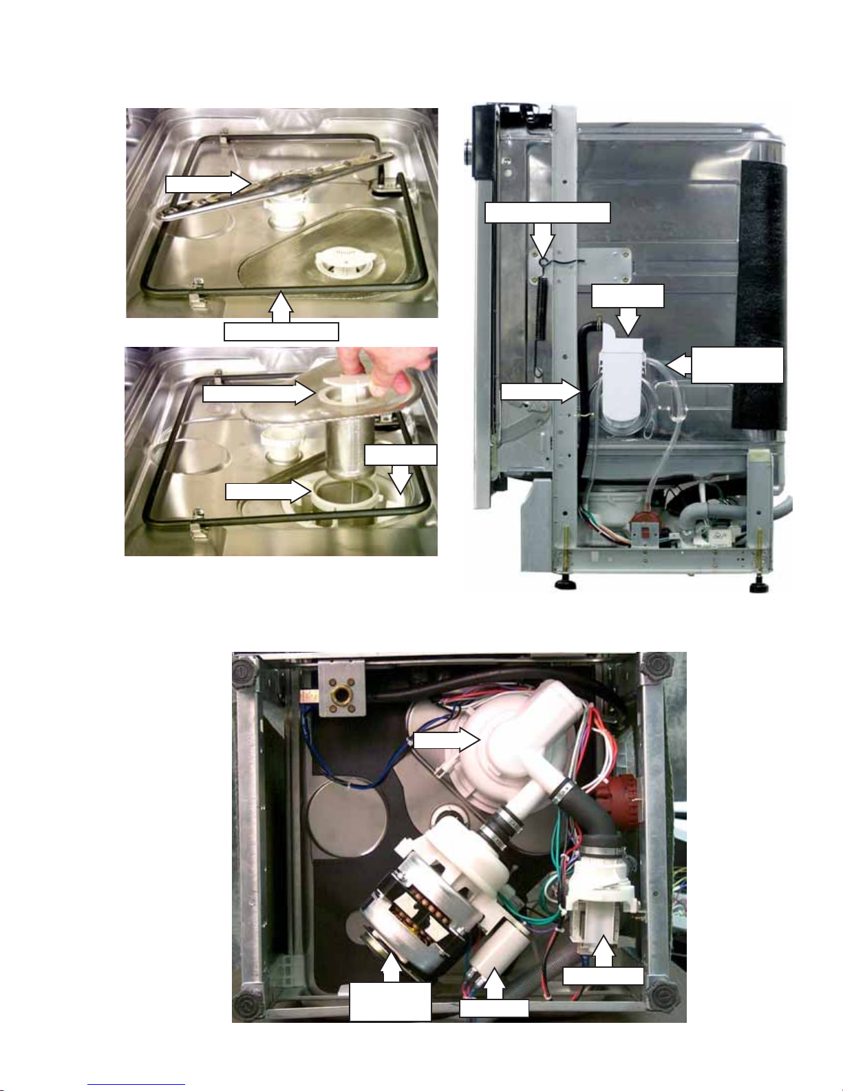
Component Locator Views .....................................................................................7
Control Panel Features ..........................................................................................6
Detergent/Rinse Module .......................................................................................15
Dishwasher Components ................................................................................... 10
Dishwasher Tub Seal .......................................................................................... 20
Door Assembly..................................................................................................... 17
Door Panel ...........................................................................................................14
Door Switch and Latch Assembly ........................................................................ 12
Drain Pump Assembly..........................................................................................24
FillFunnel .............................................................................................................21
HeatingElement ...................................................................................................20
Illustrated Parts Catalog .......................................................................................40
Introduction............................................................................................................ 4
Motor Pump Assembly ........................................................................................ 25
Nomenclature ........................................................................................................ 5
Pressure Switch.................................................................................................. 23
Schematic ............................................................................................................ 39
Side Panels ..........................................................................................................16
Specifications .........................................................................................................4
Static Dry System.................................................................................................13
Sump Assembly ...................................................................................................27
Timer .................................................................................................................... 10
Troubleshooting ....................................................................................................29
Troubleshooting Checklist .................................................................................... 34
Troubleshooting the Door Switch ......................................................................... 29
Troubleshooting the Heating Element................................................................... 30
Troubleshooting the Timer .................................................................................... 31
Troubleshooting the Wash Pump Motor ............................................................... 32
Troubleshooting theWater Fill Valve.....................................................................32
Warranty...............................................................................................................46
Washability Complaints ........................................................................................38
WaterValve ..........................................................................................................22

– 4 –
Introduction
The new Monogram 18" Built-In Compact Dishwasher has a size that
allows the unit to fit in areas as small as 18 inches (45.72 cm) wide, 22
inches (55.88 cm) long, and 34 inches (86.36 cm) high. It is compact in
size, yet delivers the performance of larger units. With a low power
usage, this product model meets ENERGY STAR®guidelines for
energy efficiency.
The Monogram 18" Built-In Compact Dishwasher has two wash levels,
a HEAVY WASH cycle, NORMALWASH cycle, LIGHT WASH cycle,
CHINACRYSTAL cycle, and a RINSE ONLY cycle.
Electrical
Rating 120 Volts, 60 Hz ±10%
Separate Circuit 4.5 to 5.5 Amps
Motor (HP) 1/5
Motor (Amps) 1 ±10%
Heater Wattage – Wash/Dry 465 ±10%
Total Amps (Load Rated) 5 ±10%
Component Resistance (OHMS)
Timer Motor 1460 ±10%
Heating Element 31 ±5%
Pump Motor Windings
Drain
Wash (Blue to Red)
27 ±10%
47 ±10%
Run Windings – Main
(Blue to Black) 22 ±10%
Water Valve Solenoid 1140 ±5%
Total Amps (Load Rated) 5 ±10%
Water Supply
Suggested Minimum
Incoming Water Temperature 120 °F to 150 °F
(49 °C to 66 °C)
Sump Water Temperature
With Outer Door In Place 145 °F ±5 °F
(63 °C ±3 °C)
Water Charge 2.54 to 3.27 Quarts
(2.4 to 3.1 Liters)
Pressure 20 Min./120 Max. (PSI)
138 Min./827 Max. (kPa)
Connection (NPT) 3/8 In. (0.95 cm)
Consumption (Total) 4.7 to 6.1 Gallons
(17.8 to 23.1 Liters)
Water Valve Flow Rate
(GPM) 1.8 ±14%
(6.81 LPM ±14%)
Water Circulation Rate (GPM) 10 ±10%
(37.85 LPM ±10%)
Water Fill Time (Seconds) 30 (±1)
Specifications

– 5 –
Model Designator
Compact 18-in.
Nomenclature
The letter designating
theyearrepeatsevery
12 years.
Example:
T = 1974
T = 1986
T = 1998
Z B D 1 8 0 0 K 0 0 S S
Brand
Z = Monogram
Product Type
BD = Built-In Dishwasher
Exterior Color
BB = Black
CC = Bisque
SS = Stainless Steel
WW = White
Model Year Designator
Engineering Model Suffix
Nomenclature
Model Number
The serial plate of your
dishwasher is located on the
tub wall, just outside the
door.
The service information sheet is
located under the control panel.
Serial Number
The first two characters of the serial number identify
the month and year of manufacture.
Example: AG123456S = January, 2001
A-JAN 2005 - H
D - FEB 2004 - G
F - MAR 2003 - F
G - APR 2002 - D
H-MAY 2001 - A
L - JUN 2000 - Z
M - JUL 1999 - V
R - AUG 1998 - T
S - SEP 1997 - S
T - OCT 1996 - R
V - NOV 1995 - M
Z - DEC 1994 - L

– 6 –
Control Panel Features
Control Timer:
HEAVYWASH
NORMALWASH
LIGHT WASH
CHINACRYSTAL
RINSEONLY For rinsing partial loads that will be washed later. Do not use detergent with this cycle.
Thiscycle is for everyday dishes and glassware.
This cycle is specifically designed for lightly soiled china and crystal.
This cycle is for medium-soiled dishes and glassware.
This cycle is for heavily soiled dishes and glassware.
START Close the dishwasher door and turn the control timer knob to the desired setting.
Water fill begins and approximately 30 seconds later, the wash action begins.
Door Latch
Switch: Automaticallyshuts off thedishwasher wheneverthedishwasher doorisopened. The
dishwasher will not resume operation until the door is closed.
Door Latch Switch Control Timer
StaticVent

– 7 –
Door Latch Switch Control Timer
Front View
Component Locator Views
Control Panel View
StaticVent
Side Panel
ControlPanel
Access Panel
Insulation

– 8 –
Interior View (With Racks)
Detergent/Rinse Module Compartment View
Compartment Lid
Sight Glass
Rinse Agent Cap
Detergent
Compartment
StaticDry Vent
Top Rack
Bottom Rack
Detergent/Rinse Module

– 9 –
Interior View of Basin (With Racks Removed)
Bottom View (Looking Up)
Right Side View
(Side Panel and Insulation Removed)
Filter Assembly
Microfilter
Clamp Nut
Heating Element
SprayArm
Fill Funnel
Pressure
Switch Hose
Fill Hose
Door Tension Spring
Sump
Drain Pump
Capacitor
Motor Pump
Assembly

– 10 –
Dishwasher Components
Throughoutthismanual,featuresandappearance
may vary from your model.
3. Remove the top screw and mark the hole
threads with a felt-tip marker.
4. Remove the bottom screw and mark the hole
threads with a felt-tip marker.
5. Open the dishwasher door.
6. Remove the 6 screws that connect the control
panel cover to the dishwasher door.
Mark the inside of
thehole threads with
a felt-tip marker.
7. Close the dishwasher door.
Timer
WARNING: Always turn off the electric power
supply before servicing any electrical component,
making ohmmeter checks, or replacing any parts.
Note: All voltage checks should be made with a
voltmeter having a full-scale range of 130 volts or
higher. After service is completed, be sure all
safety grounding circuits are complete, all
electrical connections are secure, and all access
panels are in place.
The timer allows the user to select the various
cleaning cycles of the dishwasher. The timer
controls all stages of each cycle.All electrical
functions can be traced on the charts and
diagrams provided in this service manual.
Removal and Installation
1. Disconnect the electric supply from the
dishwasher.
2. Remove the control timer knob from the
control panel cover.
Control Timer Knob

– 11 –
8. Release the door latch and allow the control
panel cover to hang against the dishwasher
door.
9. Disconnect the ground wire from the timer.
10. Disconnect the connectors. (Refer to mini-
manual or schematic diagram on page 39 for
reconnection.)
Note: When installing the timer, it is important to
align the threaded holes (A) and (B), marked in
steps 3 and 4, with holes (A) and (B) in the control
panel
Timer
ControlPanel
White Connector
Threaded Hole (A)
Threaded Hole (B)
B
A
Alignthe threaded holes
marked in steps 3 and 4
with the holes in the
controlpanel.

– 12 –
9. Remove the door switch from the door latch
mounting bracket.
10. Inspect the door latch spring. Make sure the
door latch flap fits properly in the door latch
flap hole. If the spring is misaligned, broken,
or missing, insert a new spring in the spring
post holes.
Bracket
Switch
7. Remove the 4 screws that connect the door
switch mounting bracket to the control panel
cover.
8. Pull the door switch assembly down far
enough so that the door latch cup clears the
door latch mounting bracket.
Assembly
Door Switch and Latch Assembly
The door switch and latch assembly is located on
the door assembly behind the control panel cover.
The dishwasher will not operate until the door is
closed, the latch engages the door catch (holding
the door firmly against the seal), and the normally
open contacts of the double-pole, single-throw
door safety switch are closed.
Removal and Installation
1. Disconnect the electric supply from the
dishwasher.
2. Open the dishwasher door.
Caution: Place a cloth or cardboard between the
control panel and the dishwasher door to prevent
marring the door.
3. Remove the 6 screws that connect the control
panel cover to the dishwasher door. (See
Timer, step 6.)
4. Close the dishwasher door.
5. Release the door latch and allow the control
panel cover to hang against the dishwasher
door.
Note: There are 6 terminals on the door switch.
The top 2 terminals (1) and (2) are not used. The
middle 2 terminals are marked (3) and (4). The
bottom 2 terminals are marked (5) and (6).
6. Tag and disconnect the 4 wire terminals from
the door switch.
Pull Cup
Flap
Spring

– 13 –
5. Inspect the o-ring. If the o-ring shows obvious
signs of wear or damage, replace the channel
assembly.
6. Inspect the gasket on the channel assembly.
If the gasket shows obvious signs of wear or
damage, replace the channel assembly.
Channel
O-Ring
Gasket
Static Dry System
The static dry system operates through a vent
located in the control panel. The vent allows hot
air to exit the dishwasher tub and gradually
remove moisture.
Removal
1. Open the dishwasher door.
2. Remove the 6 screws that connect the control
panel cover to the dishwasher door. (See
Timer, step 6.)
3. Release the door latch and allow the control
panel cover to hang against the dishwasher
door.
4. Remove the static vent channel cover and
assembly as shown below. Inspect the cover
for hard water/lime deposits or debris, and
clean if necessary.
Cover
(Continued next page)
Installation
1. Insert the static vent channel through the
static vent door hole.
Hole
Channel
2. Install the static vent cover to the static vent
channel, and position the control panel cover
on the dishwasher door.

– 14 –
Door Panel
Note: Make sure the edge of the control panel
cover is flush with the edge of the door.
3. Align the screw holes on the control panel with
the screw holes on the dishwasher door.
4. Install the 6 screws that connect the control
panel cover to the dishwasher door.
Cover
Makesure theedge
of the control panel
cover is flush with
the edge of the door.
Door Panel
The door panel covers the door to the dishwasher
and protects the detergent/rinse module
electronics.
Removal
1. Disconnect the electric supply from the
dishwasher.
2. Open the dishwasher door.
3. Remove the 6 screws and the door panel
from the door assembly. Do not remove the 6
screws that hold the control panel cover to the
door assembly.

– 15 –
This action moves the cover catch (2) and
releases the detergent cover.
When deactivated (3), the lever resets to rest
under the notch in the center of the connecting
rod.
When activated for the second time in a cycle, the
lever lifts the connecting rod by the notch, lifting
the rinse dispenser plunger (4) and releasing the
rinse agent. When deactivated, the lever returns
to its original starting position.
Removal and Replacement
1. Disconnect the electric supply from the
dishwasher.
2. Remove the Door Panel.
3. Remove the foam insulation.
Cover
Detergent/Rinse Module
The detergent rinse module automatically
dispenses both the detergent and the rinse agent
at the appropriate times. The module is activated
twice during a wash cycle.
The first time the module is activated (1), the lever
slides up the right-hand path of the connecting
rod.
1
4
3
2
Insulation
4. Disconnect the 2 terminals from the
detergent/rinse module.
(Continued next page)

– 16 –
5. Remove the 3 screws and top mounting
bracket.
6. Remove the 3 screws and bottom mounting
bracket.
7. Remove the detergent/rinse module from door
assembly.
Side Panels
Removal
1. Disconnect the electric supply from the
dishwasher.
2. Carefully pull the dishwasher out from its
installation.
3. Remove the screws from the top and back of
each dishwasher side panel (16 screws total).
Open the door and remove the 4 screws
securing the panels to the inside door frame.
4. Lay the dishwasher on its back. Remove the 4
screws securing the toekick to the dishwasher
and remove the toekick.
Detergent/Rinse Module
Bracket
Bracket

– 17 –
9. Remove the Door Panel.
10. Disconnect the 2 terminal lugs from the
Detergent/Rinse Module switch.
Door Assembly
Removal and Replacement
1. Disconnect the electric supply from the
dishwasher.
2. Carefully pull the dishwasher out from its
installation.
3. Remove the 6 screws that connect the control
panel cover to the dishwasher door. (See
Timer, step 6.)
4. Close the dishwasher door.
Caution: Place a cloth or cardboard between the
control panel and the dishwasher door to prevent
marring the door.
5. Release the door latch and allow the control
panel cover to hang against the dishwasher
door.
Timer
DoorLatch
5. Remove the single screw just above and to
the side of each front leveling leg. 6. Disconnect the ground wire from the Timer.
7. Disconnect the green and white multipin
connectors from the Timer.
8. Disconnect the 4 terminal lugs from the Door
Switchand LatchAssembly.
11. Remove the bolt, nut, and ground wire from
the door.
12. Pull the wire harness from the door.
Bolt, Nut, and
Ground Wire
Wire Harness
(Continued next page)

– 18 –
Caution: The star washer is easily damaged
during removal and should not be reused. Order
a new set of star washers (part number:
WD01X10254).
21. Remove the star washer from the
dishwasher door hinge.
16. Pull the spring and spring bolt key from the
mounting bracket.
17. Lift the bottom of the spring loop from the
hinge arm stud.
18. Open the dishwasher door approximately 30
degrees.
19. Lift the bottom hinge arm up from the bottom
hinge, far enough to expose the hook.
Note: There is a door hinge assembly on both
the left and right sides of the dishwasher. Both
door hinge assemblies must be removed in order
to remove the door. The procedure to remove the
right-side door hinge assembly is outlined in steps
13 through 24. The left-side door hinge assembly
removal is identical.
13. Remove the 4 screws, access panel, and toe-
kick panel from the dishwasher.
14. Remove the side panels. (See Side Panels.)
15. Mark the position of the spring bolt key in the
mounting bracket with a felt-tip marker.
Key
Bracket
Loop
Stud
20. Close the dishwasher door.
Open
Lift
Hinge
Hook
Caution: The
starwasher is
easilydamaged
andshould not
bereused.
Star Washer

– 19 –
23. Repeat steps 15 through 22 to remove the
left-side door hinge assembly.
24. Remove the dishwasher door from the
dishwasher.
22. Remove the hinge pin from the dishwasher
doorhinge.
Note: When installing the door seal, make sure it
is seated properly in the pinched metal groove.
Run your finger over the groove to make sure it is
smooth and even for a proper seal.
Bottom Door Seal
The bottom door seal prevents water leakage.
The seal is fitted in a pinched metal groove at the
bottom of the dishwasher door.
Removal and Replacement
1. Remove the Door Panel.
2. Remove the Door Assembly (steps 13 through
22 only).
3. Grab one end of the bottom door seal and peel
it away from the pinched metal groove.
WARNING: The pinched metal groove is sharp.
Wear Kevlar gloves when removing or installing
the door seal. Failure to comply may result in
personalinjury.
Pin
Tub Seal
Pinched Metal
Groove
Make sure the seal is
properlyseated in the
pinchedmetalgroove.

– 20 –
6. Disconnect the 2 terminal lugs from the
heatingelement.
3. Reverse the above procedure to install.
Note: When installing the tub seal, make sure it
is seated properly in the seal channel. Run your
finger over the seal to make sure it is smooth and
even for a proper seal. A correctly installed gasket
will have both ends of the gasket equidistant from
the bottom of the tub.
Tub Seal
Seal Channel
Dishwasher Tub Seal
The dishwasher tub seal prevents water leakage.
The seal is fitted in a seal channel that lines the
rim of the dishwasher tub.
Removal and Replacement
1. Open the dishwasher door.
2. Grab one end of the dishwasher tub seal and
peel it away from the seal channel.
Heating Element
The heating element maintains water temperature
during the wash and rinse cycles and heats the
air during the static dry cycle. (See Specifications
for heating element wattage ratings.)
To check operation, advance timer to the dry
cycle, set the selector switch for heated dry, and
close and latch the dishwasher door. Allow one or
two minutes before opening the dishwasher door
and note if heat is present.
Removal and Replacement
1. Disconnect the electric supply from the
dishwasher.
2. Open the dishwasher door.
3. Remove the top and bottom dishwasher
racks.
4. From underneath the dishwasher tub, locate
the wires leading to the heating element.
5. Pull down the nylon covers, rubber wire
protectors, and plastic strain reliefs from the
wire terminals.
Make sure the seal
isseated properlyin
the seal channel.
2 Wire Covers
2 Wire Protectors
2 Strain Reliefs
Table of contents
Other GE Dishwasher manuals

GE
GE GE Profile PDW9200JBB User instructions

GE
GE PDT760SSFSS User manual

GE
GE CDT 725 Series User manual

GE
GE GSD1200L User manual

GE
GE Monogram ZBD6800 User manual

GE
GE GDF 570 Series User manual

GE
GE Potscrubber GSC462 Owner's manual

GE
GE 165D4700P381 User manual

GE
GE GDWT608V Manual

GE
GE Monogram ZBD6400 Series How to use