2
Before you begin—Read these instructions completely and carefully.
IMPORTANT: Save these instructions for local inspector’s use.
IMPORTANT: OBSERVE ALL GOVERNING CODES AND ORDINANCES.
NOTE TO INSTALLER: Be sure to leave these instructions with the Con-
sumer.
NOTE TO CONSUMER: Keep these instructions with your Use and Care
Book for future reference.
This appliance must be properly grounded. See “Electrical Supply”, page 6.
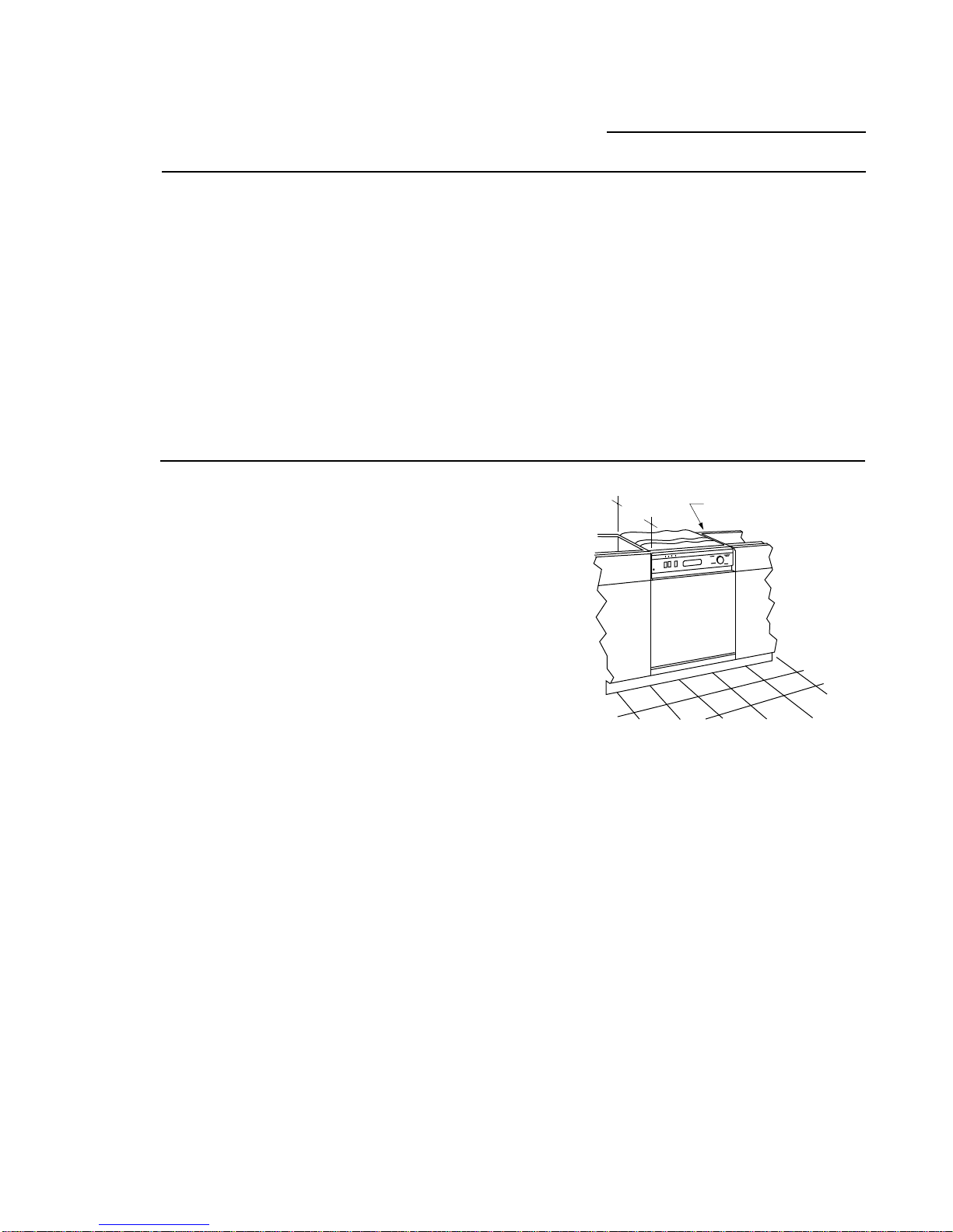
If the dishwasher is a new installation most of work must be done before the
dishwasher is moved into place. If the dishwasher is replacing another
dishwasher the connections for the dishwasher being replaced must be
checked for compatibility with this dishwasher and replaced as necessary.
If you have a question concerning the installa-
tion of this product, call the GE Answer
Center®Consumer Information Service at
800.626.2000, 24 hours a day, 7 days a week.
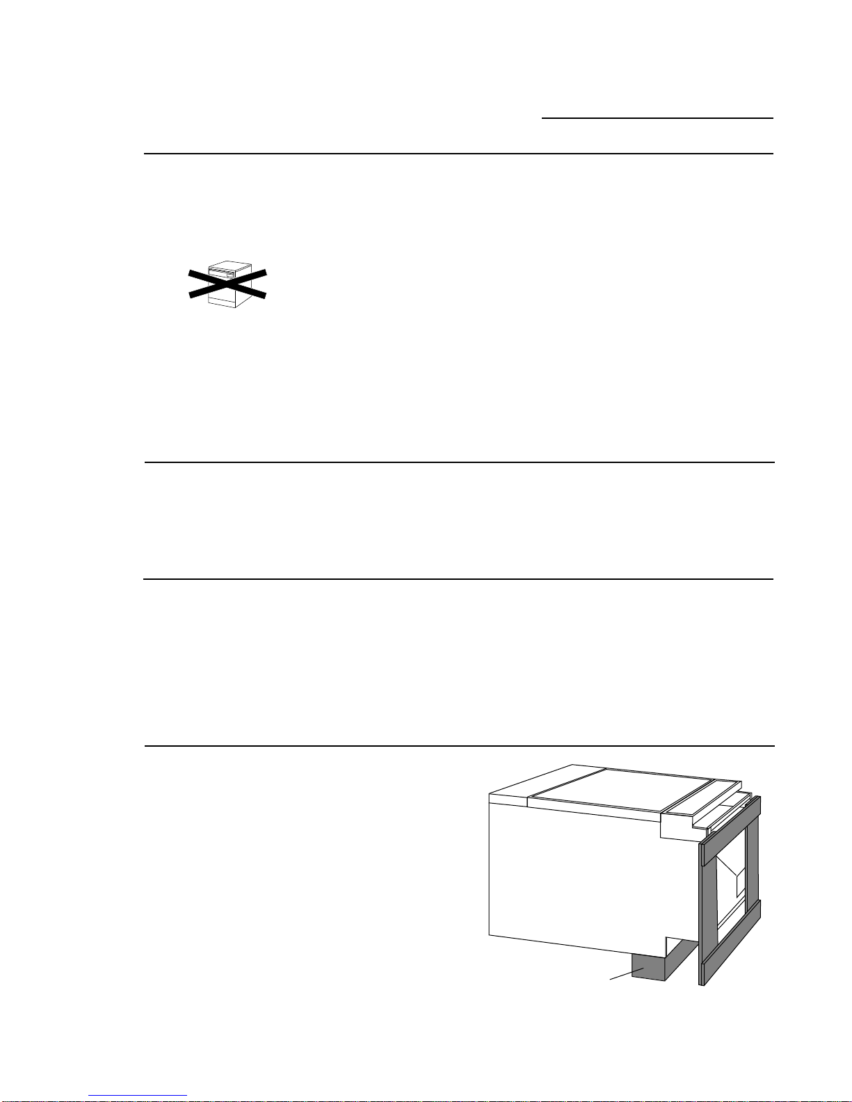
If you received a damaged
dishwasher, you should
immediately contact your
dealer or builder.
CAUTION
WARNING
Contents Design Information
Installation Notes .......................................................... 3
Standard Installation in 24" or 25" Deep Cabinets.... 3
Double Dishwashers...................................................... 4
Divider Panel Installation............................................. 4
Double Dishwashers Water Supply .............................. 4
Double Dishwashers Drain Hose, Air Gaps ................ 4
Preparation
Choosing the location .................................................. 5
Dimensions & Specifications ....................................... 5
Electrical Supply ........................................................... 6
Hot Water Supply.......................................................... 7
Prepare Drain Plumbing .............................................. 8
Step 1: Check Installation Hardware .......................... 9
Tools Required............................................... 10
Materials Required ........................................ 10
Step 2: Remove Packaging ......................................... 10
Models ZBD4600X and ZBD4700X ONLY
Step 3: Prepare 1/4" Custom Panels......................... 11
Install Custom Access Panel .......................... 11
Insert Custom Door Panel............................. 11
Consumer must supply custom panels.
Before you begin: Make sure that custom
panels are available. Custom panels must be
installed onto the dishwasher before final
installation. If they are not, the dishwasher
will have to be removed from under the
counter to install these panels.
Models ZBD4600X and ZBD4700X have a
finished front door and access panel. 1/4"
thick custom panels may be installed onto
these models.
Models ZBD4800X does not have a finished
door or access panel. A custom 3/4" thick
door and access panel must be supplied by
the consumer.
Installation instructions for both 1/4" and
3/4" thick custom panels are included in
this booklet.
Models ZBD4800X ONLY
Step 3A: 3/4" Door and Access Panels...................... 12
Remove Access Panel Assembly.................. 12
Install Custom Access Panel to Assembly .. 13
Remove Plastic Chassis Cover..................... 13
Secure Custom Panel to Dishwasher ... 14, 15
Installation – All Models
Step 4: Adjust The Door Balance ............................ 16
Step 5: Install Leveling Legs .................................... 16
Step 6: Install Water Inlet Fittings ........................... 17
Step 7: Protect the Countertop ............................... 17
Step 8: Connect Electrical (For Power Cord
Installation Only)......................................... 17
Step 9: Level the Dishwasher ................................... 18
Step 10: Install Side Filler Strips................................ 18
Step 11: Connect Drain Hose .................................... 18
Step 12: Slide Dishwasher Into Opening .................. 18
Step 13: Connect Water Line..................................... 19
Step 14: Install Drain Line ......................................... 19
Step 15: Connect Electrical (For direct Connection
to House Wiring) ......................................... 20
Step 16: Secure Dishwasher to Countertop.............. 20
Step 17: Reinstall Chassis Cover ................................ 20
Step 18: Install Toekick and Access Panel ................ 21
Install Optional Custom Toekick................ 21
Finalize Installation ..................................... 21
Questions & Answers .................................................. 23