GE Built-In Dishwasher User manual

GE Consumer & Industrial
Appliances
I
n
s
t
a
l
l
a
t
i
o
n
I
n
s
t
r
u
c
t
i
o
n
s
Bu
ilt-In Dishwasher
I
f you have questions, call 800.GE.CARES (800.432.27
37) or visit our website at
: www.ge.com
IMPORTANT
– The dishwasher MUST
be installed to allow for future removal from the enclosure
if service is required.
If you received a damaged dishwasher, you should
immediately contact your dealer or builder.
Optional Accessories – See the Owner’s Manual for available
custom panel kits.
FOR YOUR SAFETY
Read and observe all CAUTIONS and WARNINGS
shown throughout these instructions. While performing
installations described in this booklet, gloves, safety glasses
or goggles should be worn.
READ CAREFULLY.
KEEP THESE INSTRUCTIONS.
IMPORTANT
– Observe all governing codes and
ordinances.
•
Note to Installer
– Be sure to leave these instructions for the
consumer’s and local inspector’s use.
•
Note to Consumer
– Keep these instructions with your
Owner’s Manual for future reference.
•
Skill Level
– Installation of this dishwasher requires
basic mechanical, electrical and plumbing skills.
Proper
installation is the responsibility of the installer. Product
failure due to improper installation is not covered under
the GE Appliance Warranty. See warranty information.
•
Completion Time – 1 to 3 Hours
. New installations require
more time than replacement installations.
Stop Sign
BEFORE YOU BEGIN
Read these instructions completely and
carefully.
GLD6500LWW/CC/BB

PARTS SUPPLIED:
®
Two #8-18 x 5/8" Phillips special head screws,
to secure dishwasher to underside of countertop
or to side of cabinets. (In user bag.)
®
Side and top trim pieces on some models
®
Drain hose
®
Drain hose hanger
®
Clamp
MATERIALS YOU WILL NEED :
®
Ferrule, compression nut and 90° Elbow (3/8"NPT
external thread on one end, opposite end sized to fi t
water supply)
®
Thread seal tape
®
UL Listed wire nuts (3)
Materials For New Installations Only:
®
Air gap for drain hose, if required
®
Waste tee for house plumbing, if applicable
®
Electrical cable or power cord, if applicable
®
Screw type hose clamps
®
Str
ain relief for electrical connection.
®
Hand shut-off valve (recommended)
®
Water line 3/8" min. copper
®
Coupler for extending drain line, if applicable
TOOLS YOU WILL NEED:
®
Phillips head screwdriver
®
1/4" and 5/16" nutdriver
®
6" Adjustable wrench
®
Level
®
Carpenters square
®
Measuring tape
®
Safety glasses
®
Flashlight
®
Bucket to catch water when fl ushing the line
®
15/16" socket (optional for skid removal)
®
Gloves
For New Installations Only:
®
Tubing cutter
®
Drill and appropriate bits
®
Hole saw set
90° Elbow,
Ferrule and
Compression Nut
Wire Nuts (3)
Waste Tee
Electrical Cable
(or Power Cord, if applicable)
Hot Water Line
Screw Type
Hose Clamps
Coupler
Hand
Shut-Off
Valve
Side and Top Trim Pieces on some models
#8 Phillips
Special Head
Screws
5/8" long
Hole Saw Set
Level
756Dia4
756Dia6
Thread
Seal Tape
756Dia7
756Dia8
756Dia9
756Dia10
756Dia11
Air Gap
756Dia12
756Dia13
Strain Relief
756Dia16
756Dia19
756Dia18
756Dia23
756Dia25
756Dia27
756Dia28
Drain Hose
Clamp
923-02D
923-02Z
923-02C
212Dia21
1/4" and 5/16"
Nutdriver
15/16" Socket
756Dia17
756Dia20
756Dia24
756Dia15
Bucket
756Dia26
Tubing Cutter
756Dia21
Measuring Tape
756Dia22
Drill and Bits
Flashlight
Gloves
Phillips
Head
Screwdriver
Carpenters
Square
6"
Adjustable
Wrench
Safety Glasses
Installation Preparation
2
Drain Hose Hanger
Hand Valve

Method 1 – Air Gap with Waste Tee or Disposer
An air gap must be used when required by local codes and ordi-
nances. The air gap must be installed according to manufacturer’s
instructions.
PREPARE DISHWASHER ENCLOSURE
• The rough cabinet opening must be at least 24" deep, 24"
wide and approximately 34-1/2" high from floor to underside
of the countertop.
CLEARANCES:
When
installed into a corner,
allow 2" min. clearance
between dishwasher
and adjacent cabinet,
wall or other appliances.
Allow 28-3/8" min. clear-
ance from the front of
the dishwasher for door
opening. Figure B
DRAIN REQUIREMENTS
• Follow local codes and ordinances.
• Do not exceed 10' distance to drain.
NOTE:
Air gap must be used, if waste tee or disposer
connection is less than 18" above floor to prevent siphoning.
DETERMINE DRAIN METHOD
The type of drain installation depends on the following
questions.
®
Do local codes or ordinances require an air gap?
®
Is waste tee less than 18" above floor?
If the answer to either question is YES, Method 1 MUST
be used.
• If the answers are NO, either method may be used.
CABINET PREPARATION
• Drill a 1-1/2" dia. hole in the cabinet wall within the shaded
areas shown in Figure A for the drain hose connection. The
hole should be smooth with no sharp edges.
IMPORTANT
–
When
connecting drain line to disposer,
check to be sure that drain plug has
been removed. DISHWASHER WILL
NOT DRAIN IF PLUG IS LEFT IN PLACE.
Method 2 – “High Drain Loop” with Waste Tee or Disposer
Note: Avoid unnecessary service call charges. Always be
sure disposer drain plug has been removed before attaching
dishwasher drain hose to the disposer.
661Dia42
661Dia43
Figure D
• The dishwasher must be installed so that drain hose is no
more than 10' in length for proper drainage.
• The dishwasher must be fully enclosed on the top, sides and
back, and must not support any part of the enclosure.
24"
Min.
This Wall Area
must be Free
of Pipes or
wires
Plumbing and Electric Service
Must Enter Inside This Area
34-1/2"1/4"
Underside of
Countertop
to Floor
4"
24"
Min.
6"
5" 5"
4"
Cabinets
Square
and
Plumb
Floor MUST be Even
With Room Floor.
612Dia41
Remove
Hopper
Plug
923-02N
923-40A
32"
Min.
18"
Min.
Drain Hose Hanger
923-40B
32"
Min.
18"
Min.
Drain Hose Hanger
WARNING:
To reduce the risk of electric shock, fi re, or injury to
persons, the installer must ensure that the dishwasher is
completely enclosed at the time of installation.
625Dia30
Figure B
756Dia30
Clearance for Door
Opening 2" Minimum
Countertop
Dishwasher
28-3/8"
Figure A
Figure C
Installation Preparation
3

For models equipped with power cord:
Do not modify the plug
provided with the appliance; if it will not fit the outlet, have a
proper outlet installed by a qualified technician.
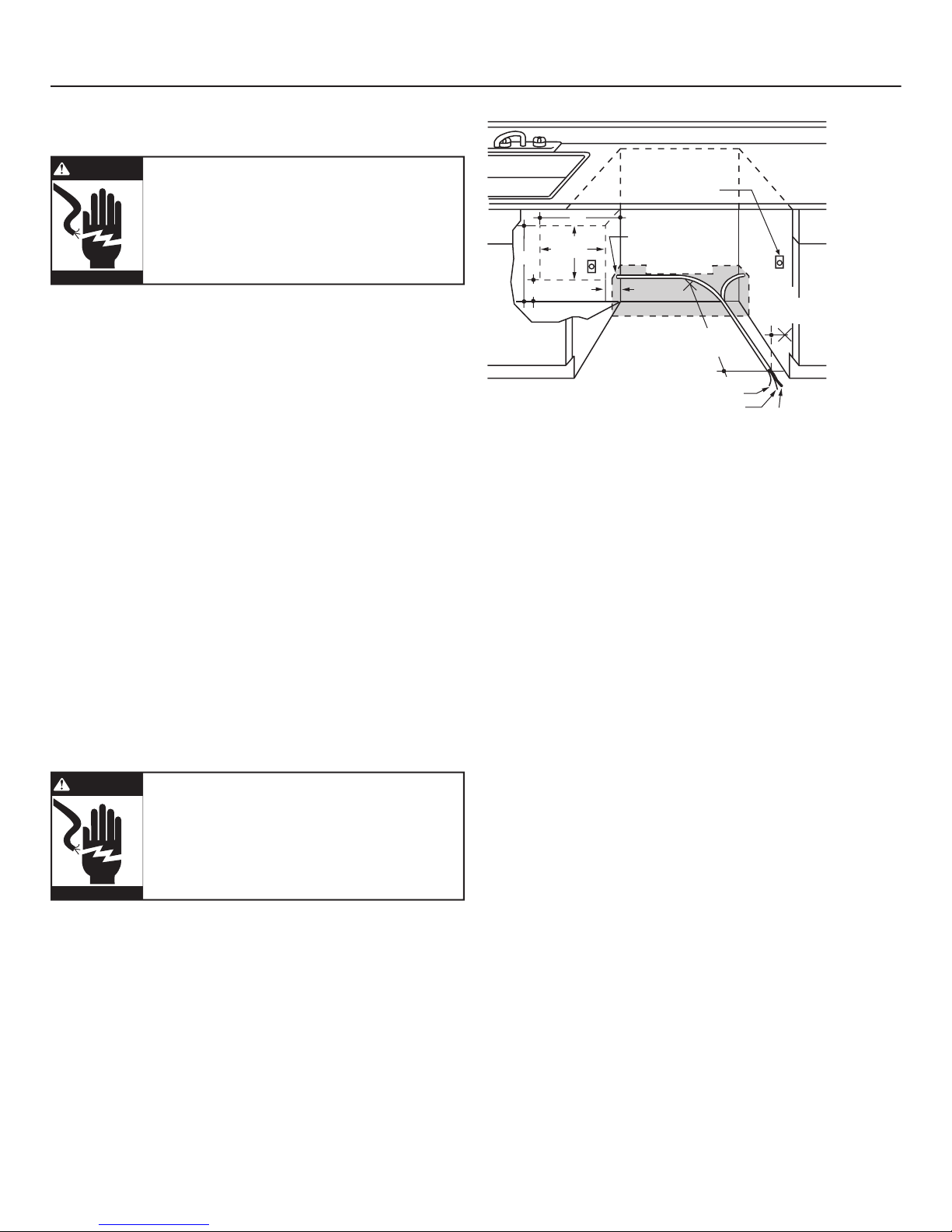
Cabinet Preparation & Wire Routing
• The wiring may enter the opening from either side, rear or the
floor within the shaded area.
• Cut a 1-1/2" max. dia. hole to admit the electrical cable. Cable
direct connections may pass through the same hole as the
drain hose and hot water line, if convenient. If cabinet wall is
metal, the hole edge must be covered with a bushing.
NOTE:
Power cords with plug must pass through a separate
hole.
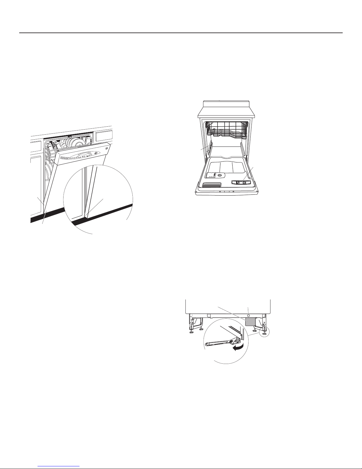
Electrical Connection to Dishwasher
Electrical connection is on the right front of dishwasher.
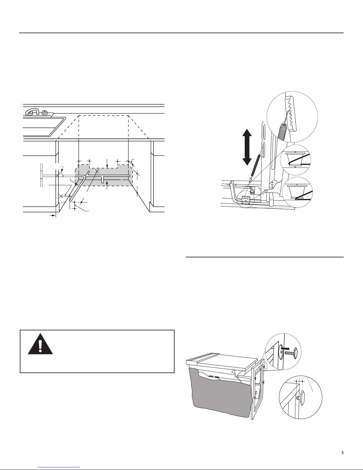
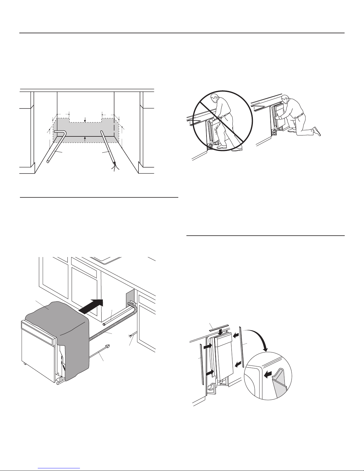
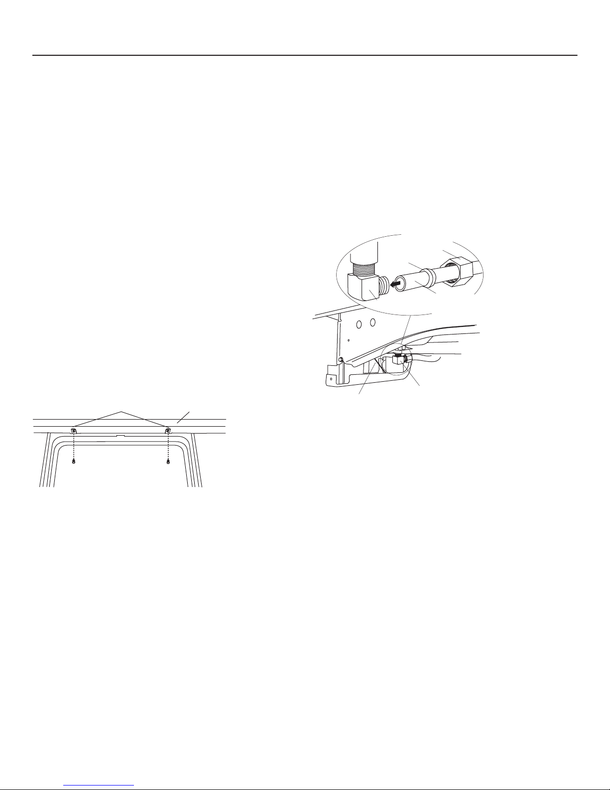
• For cable direct connections the cable must be routed as
shown in Figure E. Cable must extend a minimum of 24" from
the rear wall.
• For power cord connections, install a 3-prong grounding type
receptacle in the sink cabinet rear wall, 6" min. or 18" max.
from the opening, 6" to 18" above the floor.
FOR PERSONAL SAFETY: Remove house
fuse or open circuit breaker before
beginning installation. Do not use an
extension cord or adapter plug with this
appliance.
PREPARE ELECTRICAL WIRING
Electrical Requirements
• This appliance must be supplied with 120V, 60 Hz., and
connected to an individual properly grounded branch circuit,
protected by a 15 or 20 ampere circuit breaker or time delay
fuse.
• Wiring must be 2 wire with ground and rated for 75°C (176°F).
• If the electrical supply does not meet the above requirements,
call a licensed electrician before proceeding.
Grounding Instructions–Cable Direct
This appliance must be connected to a grounded metal,
permanent wiring system, or an equipment grounding
conductor must be run with the circuit conductors and be
connected to the equipment grounding terminal or lead on the
appliance.
Grounding Instructions–Power Cord Models
This appliance must be grounded. In the event of a malfunction
or breakdown, grounding will reduce the risk of electric shock
by providing a path of least resistance for electric current.
This appliance is equipped with a cord having an equipment
grounding conductor and a grounding plug. The plug must
be plugged into an appropriate outlet that is installed and
grounded in accordance with all local codes and ordinances.
The improper connection of the equip-
ment grounding conductor can result
in a risk of electric shock. Check with
a qualified electrician or service
representative if you are in doubt that
the appliance is properly grounded.
661Dia56A
White
18"
6"
24"
from Wall
3"
from
Cabinet
Alternate
Receptacle
Location
Ground
Black
1-1/2" Dia. Hole (Max.)
18"
6"
Receptacle
Location
Area
Figure E
Installation Preparation
#282 French
WARNING
#282 French
WARNING
4

Figure G
STEP 1 CHECK DOOR BALANCE
• With dishwasher on the wood skid, check the door balance
by opening and closing the door.
• If door drops open when released, increase spring tension. If
door closes when released, decrease tension.
Tip:
If door spring adjustment is necessary, check door
opening and closing. If door does not open easily or falls too
quickly, check spring cable routing. The cable is held in place
by “shoulders” on the pulley. Check to be sure cable has not
slipped over the pulley shoulders.
PREPARE HOT WATER LINE
• The line may enter from either side, rear or floor within the
shaded area shown in Figure F.
• The line may pass through the same hole as the electrical
cable and drain hose. Or, cut an additional 1-1/2" dia. hole to
accommodate the water line. If power cord with plug is used,
water line must not pass through power cord hole.
Figure F
Water Line Connection
• Turn off the water supply.
• Install a hand shut-off valve in an accessible location, such
as under the sink. (Optional, but strongly recommended and
may be required by local codes.)
• Water connection is on the left side of the dishwasher. Install
the hot water inlet line, using no less than 3/8" O.D. copper
tubing. Route the line as shown in Figure F and extend
forward at least 19" from rear wall.
• Adjust water heater for 120°F to 150°F temperature.
• Flush water line to clean out debris.
• The hot water supply line pressure must be 20-120 PSI.
625Dia30
6"
661Dia56
5" 5" 4"
Cabinet Face
Shut-off
Valve
4"
2" From Floor
19" From Wall
2"
From
Cabinet
1-1/2" Dia.
Hole
Hot
• Screw leveling legs back into the dishwasher frame,
approximately 1/8" from frame as shown.
756Dia39
923-10B
Approx.
1/8"
CAUTION:
CAUTION:
CAUTION:
CAUTION:
CAUTION:
Do not remove wood base until you are
ready to install the dishwasher. The dishwasher will
tip over when the door is opened.
Figure H
Note: Increase or decrease
tension as shown. Adjust
both springs to the same
tension setting to correct
balance.
Installation Preparation
STEP 2 REMOVE WOOD BASE,
INSTALL LEVELING LEGS
IMPORTANT
–
Do not kick off wood base!
Damage will occur.
• Move the dishwasher close to the installation location and
lay it on its back.
• Remove the four leveling legs on the underside of the wood
base with an adjustable
wrench or 15/16" socket.
• Discard base.
5

Toekick
Remove 2
Toekick Screws
923-02P
Front of Dishwasher
90
Elbow
Thread Seal Tape
Fill
Hose
Water Valve
Bracket
923-02Q
STEP 5 INSTALL 90°
ELBOW
• Wrap 90° elbow with
thread seal tape.
• Install a 90° elbow onto
the water valve.
• Do not over tighten
90° elbow. Water
valve bracket could
bend or water valve
fitting could break.
• Position the end of the
elbow to face the rear
of the dishwasher.
Figure K
STEP 3 REMOVE TOEKICK
• Remove the
2 toekick screws
and toekick.
Set aside for use
in Step 18.
• Connect incoming power cord white (or ribbed) to dishwasher
white, black (or smooth) to black and ground to dishwasher
green wire. Use UL listed wire nuts of appropriate size.
• Replace junction box cover. Be sure wires are not pinched
under the cover.
Figure J
Figure I
212Dia25
White
Ground Black
Check That White, Black and
Green Dishwasher Wires Are Threaded
Thru Small Hole in Bracket
Remove
Junction Box
Cover
Insert Power
Cord Wires Thru
Strain Relief
and Tighten
Use UL Listed
Wire Nuts
A
B
C
D
STEP 5A INSTALL DRAIN HOSE TO
DISHWASHER DRAIN PORT
Skip this step if drain hose has been pre-installed.
In this step you will need the drain hose set aside prior
to Step 1.
• Stand dishwasher upright.
• Remove hose clamp attached to drain hose. Place hose
clamp over the small end of the drain hose.
Tip:
Prevent drain hose damage and possible leaks.
Be careful not to nick or cut the drain hose.
• Push the small end of the drain hose over the drain port of
the dishwasher, see Figure L.
• Make sure hose is fully seated on the dishwasher drain port.
• Position hose clamp against the front lip of the drain hose
and tighten clamp.
Hint: for leak free connections:
• Insert hose against stop on pump.
• Position clamp against front lip of drain hose.
• Tighten clamp to at least 15 inch-pounds of torque.
923-41A
Hose Clamp
Shoulder Stop
Drain Outlet
Flapper Valve
Do Not Remove
Figure M
923-41B
Front Lip
of Hose
Stop
Stop
Installation Instructions
STEP 4 INSTALL POWER CORD
Skip this step if dishwasher will be direct wired or
has a factory installed power cord.
Use Power Cord Kit WX09X70910, available for
purchase from an authorized GE Appliance Dealer.
The power cord and connections must comply with
the National Electrical Code, Section 422 and/or local
codes and ordinances.
• Maximum power cord
length is 6 feet.
6
Figure L
Figure L
Figure L
Figure L
Figure L
Figure L
Figure L
Figure L
Figure L
Figure L

212Dia9
Power Cord
(If Used)
Insulation
Blanket Water
Line
Maximum Drain Hose
Length 10'
House
Wiring
Drain
Hose
STEP 9 INSTALL TRIM PIECES
Skip this step if trim is not supplied with the
dishwasher.
• Locate trim strips inside dishwasher.
• Press trim onto the tub flange on each side. Start with the top
edge, pressing on as you move towards the bottom.
• Press the two top trim pieces on each side of the latch.
• Open and close the door to check that trim does not bind and
does not interfere with door latch.
STEP 8 SLIDE DISHWASHER PARTIALLY
INTO CABINET
DO NOT PUSH AGAINST FRONT PANEL WITH KNEES.
DAMAGE WILL OCCUR.
• Slide dishwasher into the opening a few inches at a time.
• As you proceed, pull the drain hose through the opening
under the sink. Stop pushing when the dishwasher is a few
inches forward of adjacent cabinets.
• Make sure drain hose is not kinked under the dishwasher and
there is no interference with the water line, wiring and/or any
dishwasher component.
Figure O
STEP 7
INSTALL DRAIN HOSE,
THROUGH CABINET
• Position dishwasher in front of cabinet opening. Insert drain
hose into the hole in cabinet side. If a power cord is used,
guide the end through a separate hole.
STEP 6 POSITION WATER LINE
AND HOUSE WIRING
• Position water supply line and house wiring on the floor of the
opening to avoid interference with base of dishwasher and
components under dishwasher.
Figure N
Do Not Push Against
Front Door Panel With
Knee. Damage to The
Door Panel Will Occur.
756Dia46
Trim Strip
Trim
Strip
Trim
Strip
756Dia47
Figure Q
661Dia32
Water
Line House
Wiring
5" 5"
4" 4"
6"
6"
4"
Tip: Position water line and house wiring on the fl oor
to avoid interference with base of dishwasher.
Installation Instructions
7
Figure P

Figure S
STEP 10 PUSH DISHWASHER INTO
FINAL POSITION
Tip: Check tub insulation blanket, if equipped. It should be
positioned so it is not “bunched up” or interfering with door
springs. Check by opening and closing door.
• Push dishwasher into the cabinet. The edges of the
dishwasher door should be behind the cabinet frame and
evenly aligned with the front face of cabinet doors.
• Carefully open and close the door to ensure the door panel is
not catching or rubbing on the cabinet frame.
Figure R
STEP 11 LEVEL DISHWASHER
IMPORTANT – Dishwasher must be level
for proper dish rack operation and wash performance.
• Place level on door and rack track as shown. Check to make
sure that the dishwasher is level.
923-02Y
Check
Level
Side-
to-Side
Check
Level
Front-
to-Back
• Level the dishwasher by adjusting the four leveling legs
individually.
• If adjustment to the right rear leveling leg is required, loosen
junction box bracket screw (through the access hole) and
rotate bracket clockwise to provide additional access.
Tip: Pull lower rack out, about halfway. Check to be
sure the rack does not roll forward or back into
dishwasher. If the rack rolls in either direction, the
dishwasher must be leveled again.
• If door hits tub, the dishwasher is not installed correctly.
Adjust leveling legs to align door to tub.
923-02AA
Access HoleJ. Box
Turn Legs
to Adjust
Figure T
Installation Instructions
8

756Dia55
Brackets Wood Countertop
In this step you will need the 2 Phillips special head
screws set aside prior to Step 1.
The dishwasher must be secured to the countertop or
the cabinet sides. For dishwashers which require side mounting
brackets, order part GPF65 from your authorized GE Appliance
Dealer.
Tip: Prevent door panel and control panel damage.
Dishwasher must be positioned so the front panel and
control panel do not contact the adjacent cabinets or
countertop. Mounting screws must be driven straight
and fl ush. Protruding screw heads could scratch the
door panel or control panel and interfere with door
operation.
Secure dishwasher to underside of wood countertop.
• Recheck alignment of the dishwasher in the cabinet. Refer to
Step 10, Figure R and Step 11. Door panel
and/or control panel must not hit cabinets or countertop.
• Fasten the dishwasher to the underside of the countertop
with the 2 Phillips special head screws provided. Refer to
Figure U. Make certain screws are driven straight and flush to
prevent panel damage.
STEP
1
2 POSITION DISHWASHER, SECURE
TO COUNTERTOP OR CABINET
Figure U
STEP 13 CONNECT WATER SUPPLY
Connect water supply line to 90° elbow.
• Slide compression nut, then ferrule over end of
water line.
• Insert water line into 90° elbow.
• Slide ferrule against elbow and secure with compression nut.
IMPORTANT
–
Check to be sure that door
spring does not rub or contact the fi ll hose or water supply line.
Test by opening and closing the door. Re-route the lines if a
rubbing noise or interference occurs.
Figure V
90° Elbow
Ferrule
90° Elbow
Door Spring
756Dia57
Hot Water
Supply Line
Compression
Nut
Installation Instructions
9

• If a longer drain hose is required, add up to 42" of length for
a total of 10' to the factory installed hose. Use 5/8" or 7/8"
inside diameter hose and a coupler to connect the two hose
ends. Secure the connection with hose clamps.
Figure W
STEP 14 CONNECT DRAIN LINE
FOLLOW ALL LOCAL CODES AND ORDINANCES.
Identify the type of drain hose you have. The molded
end of the drain hose will fi t 5/8" through 1" diameter
inlet ports on the air gap, waste tee or disposer.
• Determine size of inlet port
• Cut drain hose connector on the marked line, if required, to fit
the inlet port.
DRAIN LINE INSTALLATION
• Connect drain line to air gap, waste tee or disposer
using either previously determined method.
Waste Tee Installation
Method 1 – Air gap with waste tee or disposer
Disposer Installation
Waste Tee Installation
Method 2 – “High drain loop” with waste tee or disposer
Disposer Installation
Figure Y
Figure Z
• Secure the drain hose to the air gap, waste tee or disposer
with clamps.
NOTE:
TOTAL DRAIN HOSE LENGTH MUST NOT EXCEED 10 FEET
FOR PROPER DRAIN OPERATION.
IMPORTANT
–
When connecting drain line to
disposer, check to be sure that drain plug has been removed.
DISHWASHER WILL NOT DRAIN IF PLUG IS LEFT IN PLACE.
TIP:
Avoid unnecessary service call charges. Always be sure
disposer drain plug has been removed before attaching
dishwasher drain hose to the disposer.
Figure X
756Dia60
756Dia61
756Dia59
Hose Clamp
Coupler Hose Clamp
923-02B
Cutting Line
1" 5/8"
IMPORTANT: Do not cut corrugated
portion of hose
Remove
Hopper
Plug
923-02N
Installation Instructions
10

STEP 16 PRE-TEST CHECK LIST
Review this list after installing your dishwasher to avoid
charges for a service call that is not covered by your
warranty.
®
Check to be sure power is OFF.
®
Open door and remove all foam and paper packaging.
®
Locate the Owner’s Manual in the literature package.
®
Read the Owner’s Manual for operating instructions.
®
Check door opening and closing. If door does not open and
close freely, check for proper routing of spring cable over
pulley. If door drops or closes when released, adjust spring
tension. See Step 1, Figure G.
®
Check to be sure that wiring is secure under the dishwasher,
not pinched or in contact with door springs or other
components. See Step 8.
®
Check door alignment with tub. If door hits tub, level
dishwasher. See Steps 11 and 12.
®
Pull lower rack out, about halfway. Check to be sure it does
not roll back or forward on the door.
If the rack moves, adjust leveling legs. See Step 11.
®
Check door alignment with cabinet. If door hits cabinet,
reposition dishwasher. See Step 12.
®
Check that door spring does not contact water line, fill hose,
wiring or other components. See Step 13.
®
Verify water supply and drain lines are not kinked or in
contact with other components. Contact with motor or
dishwasher frame could cause noise.
®
Turn on the sink hot water faucet and verify water
temperature. Incoming water temperature must
be at least 120°F and no more than 150°F for best wash
performance.
®
Add 2 quarts of water to the bottom of the dishwasher to
lubricate the pump seal.
®
Turn on water supply. Check for leaks. Tighten connections
if needed.
®
Remove protective film if present from the control panel and
door.
®
Avoid service call charges by ensuring there is an air gap or
drain hose routed through the required 32" minimum height.
STEP 15 CONNECT POWER SUPPLY
If a power cord with plug is used, proceed to Step 16.
• Remove junction box cover.
• Secure house wiring to the back of the junction box with a
strain relief.
• Locate the three dishwasher wires, (white, black and green)
with stripped ends. Insert dishwasher wires through the small
hole in the junction box. Use wire nuts to connect incoming
ground to green, white to white and black to black.
• Replace junction box cover. Check to be sure that wires are
not pinched under the cover.
If house wiring is not 2-wire with
ground, a ground must be provided by
the installer. When house wiring
is aluminum, be sure to use UL
Listed anti-oxidant compound and
aluminum-to-copper connectors
Installation Instructions
11
#282 French
WARNING
Figure
AA
212Dia26
White
Ground Black
Check That White, Black and
Green Dishwasher Wires Are Threaded
Thru Small Hole in Bracket
Remove
Junction Box
Cover
Insert Power
Cord Wires Thru
Strain Relief
and Tighten
Use UL Listed
Wire Nuts
A
B
C
D

• Align the toekick with the bottom edge and make sure it is
against the floor.
• Insert and tighten the two toekick attachment screws. The
toekick should stay in contact with the floor.
TIP:
Make sure toekick is against floor to minimize noise.
Figure BB
STEP 19 LITERATURE
• Be sure to leave complete literature package and
Installation Instructions with the consumer.
STEP 18 REPLACE TOEKICK
• Place toekick against the legs of the dishwasher.
STEP 17
DISHWASHER WET TEST
®
Turn on power supply (or plug power cord into outlet,
if equipped).
®
Latch door.
®
Push “Rinse Only” button.
®
Push start/reset pad once. Dishwasher should start.
®
Check to be sure that water enters the dishwasher. If water
does not enter the dishwasher, check to be sure that water
and power is turned on.
®
Check for leaks under the dishwasher. If leak is found, turn
power supply off, then tighten connections. Restore power
after leak is corrected.
®
Check for leaks around the door. A leak around the door
could be caused by door rubbing or hitting against adjacent
cabinets. Reposition the dishwasher if necessary. See
Step 12.
®
The dishwasher will drain and turn off about 5 minutes after
it was started. Check drain lines. If leaks are found, turn
power supply off and correct leaks as necessary. Restore
power after corrections are made. See Step 5A and 14.
®
Open dishwasher door and make sure most of the water has
drained. If not, check that disposer plug has been removed
and/or air gap is not plugged. See Step 14.
®
Press Start/Reset pad once again and run dishwasher
through another “Rinse Only” cycle. Check for leaks and
correct if required.
Toekick
Attachment Screws
756Dia66
Installation Instructions
GE Consumer & Industrial
General Electric Company
Louisville, Kentucky 40225
ge.com
© 2005 General Electric Company
Pub. No. 31-
30
590
Dwg. No
.
206C1559P
132
ND
05
D
-1
2
94
(
4
/05
)
SPECIFICATIONS SUBJECT TO CHANGE WITHOUT NOTICE
Other manuals for Built-In Dishwasher
9
Table of contents
Other GE Dishwasher manuals

GE
GE HDA3500NCC - Dishwasher w/ 5 Wash Cycles User manual

GE
GE GSD750 User manual

GE
GE ADT521PGFBS User manual

GE
GE GLC4000 Series User manual

GE
GE GSD500P User manual

GE
GE Spacemaker GSM1860NSS Manual

GE
GE HDB920 User manual

GE
GE GD 550 Series User manual

GE
GE CDW9380NSS User manual

GE
GE Lave-vaisselle User manual