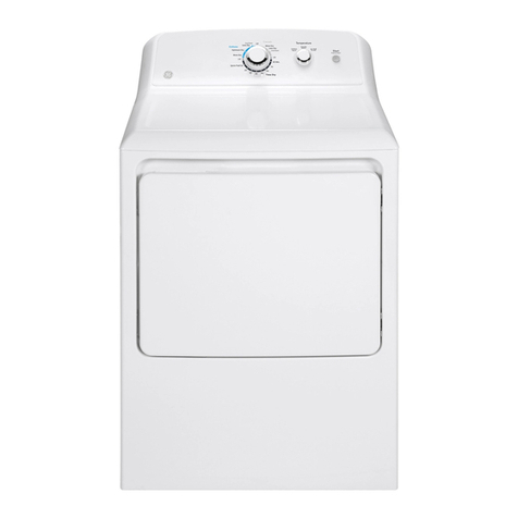
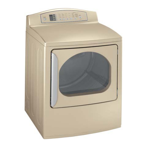
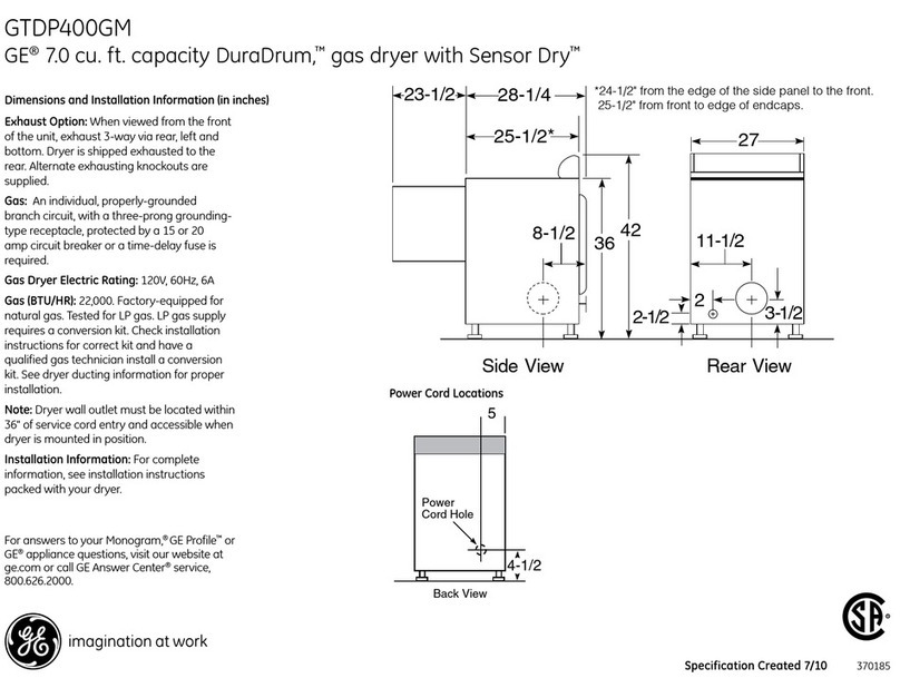
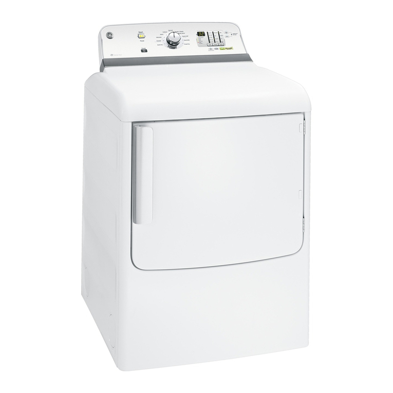
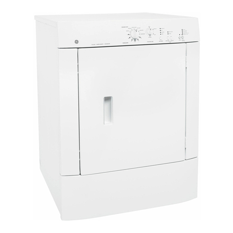
GE Clothes Dryer User manual

This information was supplied to me by CAMCO (www.camco.ca), the appliance
manufacturers and has been typed again for clarity, ease of duplicating and sending
this information. Call if you have questions, www.thermoguy.com
RULES FOR BEST PERFORMANCE
Best Performance Means
•Safety
•Faster Drying Times
•Less Energy Consumption
•Longer Dryer Life –Less Dryer Wear
•Longer Clothes Life –Less Clothes Wear
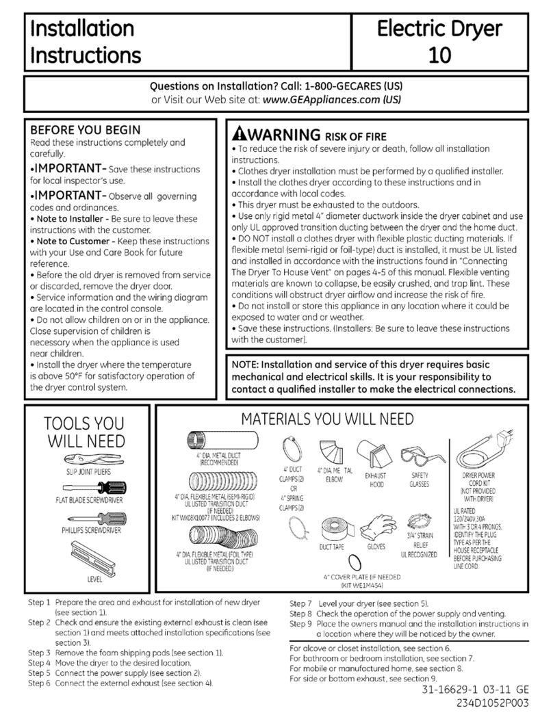
•Make sure to refer to the installation instructions specific to the dryer model being
installed (get copy from Sales Rep: 1-800-361-3400).
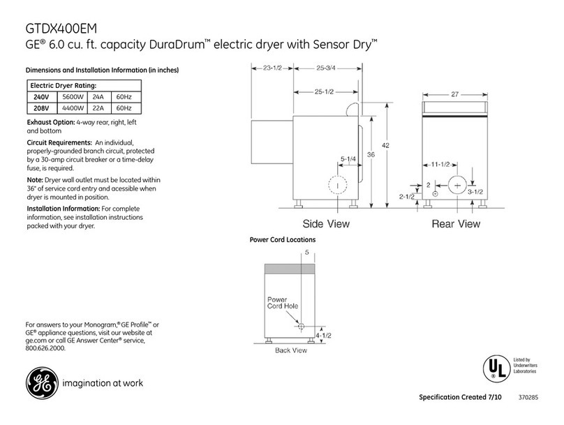
•Use 240 volts. 208 volts increases drying time by about one third.
•Use 4” metal ducting. Never use plastic ducting. It increases dry time, traps lint
and may be a fire hazard. See page 3.
•Use 4” wall caps.See Page 4
•Use louvered doors for closet installations to get sufficient air to dryer. See Page 6
•Do not use screens in vents. Screens clog with lint and become safety
hazard…….. Page 4.
•Minimize total exhaust duct length…..Page 4.
•Minimize 90-degree turns. Use 45 degree turns instead of 90 degree turns when
possible……Page 5.
•Leave 4’ minimum between turns and bends when possible….Page 5.
•Secure all joints with fasteners that do not extend into ductwork. Screws trap lint.
Seal all joints with duct tape…..Page 6.
•Insulate ducting that will be in a cool ambient during drying to prevent
condensation accumulation….Page 7.
•Use a minimum of 1/8” per foot (10mm per meter) pitch on horizontal ducting
runs, when possible, to prevent any condensate from accumulating in
ducting....Page 7.

Section 1----- General Information Page 4
Section 2----- Multi-Unit Installation Page 9
THERE IS A NEED FOR
ACCURATE INFORMATION
The variety of floor plans and laundry
locations, coupled with an increasing
number of building codes and
restrictions, indicates a need to advise
planners well in advance of installation
about exhaust requirements and other
pertinent information. This is especially
true in multi-family construction.
Failure to comply with the
manufacturer’s recommendations when
installing a washer and dryer can void
warranty provisions, cause local
authorities to refuse to grant a certificate
of occupancy, or may even result in legal
liability should the user experience
personal or property damage as a result
of the installation.
GOOD PRACTICE IN
EXHAUSTING DRYERS
An inadequate or improperly installed
dryer exhaust system will, at the very
least, result in a loss of drying
performance and an excess energy
consumption.
All dryers must be exhausted to the
outdoors. When the dryer is in operation,
the warm humid air passes thorough the
dryer lint filter where the lint is
collected. Fine particles of lint will pass
through the lint screen and will be
pushed through the exhaust duct to the
outdoors. If outdoors exhausting is not
provided, this lint and moist air will be
exhausted into the room. This condition
could create undesirable effects
including:
•Aggravating allergic conditions
•Sweating of cold water pipes,
windows and walls
•Rusting of metal
•Peeling of paint
•Loosening of wall paper
The indoor exhausting also affects dryer
performance, since it re-circulates highly
humid air from the room. It usually
results in longer drying times.
Index
?
?
?

SECTION ONE
The Exhaust Requirements
Minimizing the length of ductwork and the number of turns in an exhaust system
minimizes the potential for lint to settle and accumulate in the exhaust duct and in the
interior cabinet of the dryer. Refer to your specific dryer installation instructions for
recommended permissible maximum duct length.
1. Wall Caps and other Terminations
All exhaust systems must be terminated in a manner that will prevent back drafts from
outdoors as well as prevent birds or other wildlife from building nests or taking refuge in
the ductwork. The wall cap should present minimal resistance to the flow of exhaust air
and should prevent lint and water accumulation and prevent clogging.
The preferred termination is either a dampered wall cap having a 4” wide opening
or a movable louvered wall cap.
A two and a half inch wall cap resists airflow and increases drying time. It must be
installed with the opening down and should be installed at a minimum of 12 inches above
ground level or any other obstruction. Special consideration should be given in areas
where heavy snowdrifts are likely to occur to ensure the wall cap does not become
obstructed. Other types of terminations, such as roof vents or louvered plenum chambers,
are acceptable providing they are equivalent to the 4” dampered wall cap. They must
contain at least 14 square inches of ventilation area and afford adequate protection
against back drafts
The dryer exhaust must not terminate in an ordinary chimney, under an enclosed house
floor or crawl space, or into an attic, since any accumulated lint could create a fire hazard
and the moisture could cause damage. Never terminate the exhaust into the common
duct or plenum with a kitchen hood exhaust since the combination of grease and lint
could create a fire hazard.
Exhaust ducts
must not contain screens or other filtering devices
anywhere along
their full length. They become clogged with lint and become a safety hazard.
?
?
?
?
?

2. Separation of turns in the ductwork
All turns in the exhaust system, external to the dryer itself, including the distance from
the last turn to the dampered wall cap, should be separated by at least 4 feet of straight
metal duct. This requirement will reduce the added resistance to airflow, which results
from rapid changes of airflow direction inside the ducting.
If two turns must be closer than 4’, deduct 10’ from the maximum lengths shown in.
3. Treatment of turns other than 90 degrees
One turn of 45 degrees or less may be ignored. Two such turns should be treated as one
90-degree. Each turn over 45 degree should be treated as one 90 degree. Refer to specific
dryer installation for maximum duct lengths and for allowable 90 degree bend.
Note: Some dryers are limited to only rear exhausting. Consult the installation
instruction for the type of dryer being used.
4. Use of Flexible metal ducting
We recommend the use of 4” diameter rigid metal ducting. Flexible ducting is
susceptible to unforeseen restrictions, turns or kinks. However, if flexible metal
ducting must be used, the following precautions must be adhered to:
a. Use only 4” diameter metallic flexible ducting.
b. Never use foil or other thin ducting that can be easily punctured with a
screwdriver or nail.
c. The flexible duct must not be allowed to collapse, kink or sag when the
dryer is pushed to its final installed position. It is suggested that required
turns in the exhaust system be made with rigid elbows.
d. Minimize ducting length. Don’t exceed the maximum allowable duct
lengh specified in the installation instructions. Account for all bends.
e. To reduce the risk of fire, NEVER USE FLEXIBLE PLASTIC OR
OTHER COMBUSTIBLE DUCTWORK.
?
?
?
?

5. Sealing of joints
All duct joints should avoid leaks. Duct joints should be made air and moisture tight by
wrapping the overlapped joints with duct tape. The male ends of each section of duct
should point away from the dryer. Do not assemble the ductwork with screws or other
fasteners that extend into the duct. They will serve as a collection point for lint.
6. Air Supply to Dryer
ALL DRYERS NEED A GOOD SUPPLY OF AIR (UP TO 160 CFM) TO
OPERATE PROPERLY.
•ALCOVE OR CLOSET INSTALLATION
Minimum clearances are required between dryer cabinets, adjacent walls, overhead
cabinets, ceilings and other combustible surfaces. Consult specific dryer installation
instructions for requirements.
Consideration must be given to provide adequate clearances for air supply,
installation, servicing and cleaning.
Closet doors must be louvered or otherwise ventilated and must contain at least 60
square inches of open-air passage area. If the closet contains both a washer and a
dryer, doors must contain 120 square inches of open-air passage.
•REGULAR DRYER INSTALLATION
When installed in closed laundry room, leave gap at bottom of door to allow air inlet for
proper operation of dryer.
Ventilated Closet Door
?
?

7. Water Condensation
The condensation of water in a dryer exhaust system is caused by the moisture in the
exhausted air contacting the cold inner surfaces of the ductwork. Condensation, which
forms at the beginning of the drying cycle, will dissipate quickly after the ductwork
becomes heated. However, if the ductwork passes through an area, which keeps it cool
throughout the drying cycle, considerable condensation can be expected. This can result
in a rapid accumulation of lint in the ductwork.
Ductwork, which runs through an unheated area or which is situated adjacent to an air
conditioning duct should be insulated to avoid such condensation problems. All joints
should be tight to avoid leaks and, where feasible, the duct should be sloped at least 1/8”
per foot (10 mm per meter) towards outdoors.
8. Accessibility for cleaning
Since it may be necessary from time to time to remove lint from the inside of the
ductwork, it is important that the exhaust system be installed with a provision for periodic
inspection and cleaning. Some provision should be made for access to turns and straight
runs of duct installed in an enclosed area, such as above plastered ceilings. Special
consideration should be given to the amount of maintenance required for roof caps on
vertical installations, since the user cannot be expected to make frequent inspections or
cleanings.
?
?

9. In Line Exhaust (Booster) Fans
•Use of In Line exhaust (booster) fan for single unit installation is not
recommended:
-Operator may forget to turn it on
-It may block
-It may fail without operator noticing it.
•For multi-unit installation, refer to Section II of this booklet
Single Family-type Dwellings
For more detailed information, refer to the installation instructions for the specific dryer
model selected.
Mobile or Manufactured home installation
Gas Dryer installation must conform with local Gas Codes and with CGA B149.1 or
B149.2 (Installation code for Gas Burning Appliances and Equipments).
All Dryers Installation must conform to Manufactured Home Construction and Safety
Standard, Title 24 CFR, Part 32-80.
The dryer MUST be exhausted to the outdoors with the termination (wall cap, etc.)
securely fastened to the mobile home structure.
The exhaust MUST NOT be directed underneath the mobile home.
?

Multi-Unit Installation
Multi-Unit Systems
Accurate installation of a good dryer exhaust system in multi-family construction is
especially important. The exhaust ducting restrictions applied by this type of construction
should cause the planner to be more concerned than in single-family construction.
When the total length of the exhaust duct or the number of turns in the system exceed the
maximum limitations recommended by the dryer manufacturer, the planner must seek an
alternate solution. One solution could be to install a common ducting system that is
capable of handling the discharge of several dryers at various points along the system.
The scope of the subject is far to broad to be extensively described within this
publication. Sufficient information is presented, however, to make the planner aware of
the importance of special attention to the subject.
Two types of common ducts are generally used: (1) the common fan assisted dryer
exhaust stack (with an auxiliary roof fan); and (2) the chimney type common dryer
exhaust.
Fan assisted stack and chimney designs must meet all local code requirements. It is
suggested that professional engineering counsel should be sought in these matters.
It is suggested that dryers be installed as close to the common duct as possible.
Dryers discharges must be offset to prevent one unit from exhausting directly into
another.
See Illustration No.1.
Illustration No.1.
Section 2
?

Common Fan Assisted Dryer Exhaust Stack
(Auxiliary Roof Fan Systems)
The stack outlet (see Illustration No.2) must be fitted to a continuous duty exhaust fan
rated to handle the stack air volume for the total number of dryers on the system. Periodic
cleaning of the exhaust fan is necessary to maintain efficient operation.
The bottom of the stack should contain a barometric damper to prevent drawing air
through the dryers not in use, and a lint cleanout access door. The damper should be
adjusted to just open with all dryers on and the continuous duty exhaust fan operating.
The weighted damper in the individual dryer ducts should be adjusted so that it will just
close with all dryers off and the continuous duty exhaust fan operating. The fan should be
running all the time.
The duct system from each individual dryer must meet the turn and length requirements
noted in Section 1.
The required stack diameter for air volumes of 200 CFM to 3000 CFM can be determined
from Illustration No.3 and calculations on Page 11.

?

Chimney Exhaust System
The chimney must be fire resistant and large
enough to accommodate the volume of air
exhausting from the dryers. Consideration
must be made for lint buildup, excessive
chimney pressures, back drafts and other
technical factors, which will influence the
performance and the safety of the system.
A lint clean-out access door should be
included at the bottom of the chimney.
Each dryer must have a 4” diameter back
draft damper, adjusted so that it will just
close with the dryer inoperative. This will
prevent the exhaust and lint of one dryer
from going into another dryer and its room.
The duct system for each individual dryer
must meet the turn and length requirements
as noted in Section 1. Use the specs for a 2
½” exhaust hood for proper dryer
performance. Include the 90-degree elbow
and all ducting in the chimney in your
calculations. The 22” (minimum) of vertical
ducting in the chimney reduces backpressure
and is required for proper dryer
performance.
For information on venting kits and
accessories, please call:
1-800-361-3400 (In Canada)
1-800-GE-CARES (in U.S.A.)
?
Table of contents
Other GE Dryer manuals

GE
GE Profile DPVH890EJ Operating instructions

GE
GE Profile DPGT750 Operating instructions

GE
GE DBVH512 User manual

GE
GE PTD90EBMTRS User manual

GE
GE DDE7109V User manual

GE
GE Profile Harmony PTDS850EM Manual

GE
GE GFDS350GLWW User manual

GE
GE GTX22EBMKWW User manual

GE
GE DNCD450EGAWC User manual

GE
GE DBXR300GG Manual