Installation
EXHAUST SYSTEM CHECK LiST(cont.)
SEPARATIONOF TURNS
For best performance, separate all turns by at least 4 ft. of
straight duct, including distance between last turn and exhaust
hood.
TURNSOTHERTHAN90°
, One turn of 450or less may be ignored.
, Two a50turns should be treated as one 90°turn.
, Eachturn over450should be treated usone 900turn.
SEALINGOFJOINTS
, Alljoints should be tight to avoid leaks.Themale end of each
section of duct must point away from the dryer.
, The duct shall not be assembled with screws or other
fastening means that extend into the duct and catch lint.
, Ductjoints can be made air and moisture-tight by wrapping
the overlappedjoints with duct tape.
, Horizontal runs should slope down toward the outdoors 1/4
inchper foot.
INSULATION
Duct work that runs through an unheated area or is near air
conditioning should be insulated to reduce condensation and
lint build-up.
[-4-]EXHAUST CONNECTION
WARNING -TOREDUCETHERiSK
OF FiRE OR PERSONAL iNJURY:
,This clothesdryer must be exhaustedto the outdoors.
, Useonly#' rigid metal ducting for the home exhaustduct.
, Use only a" rigid metal or UL-listedflexible metal (semi-
rigid or foil-type) duct to connect the dryer to the home
exhaust duct. It must be installed in accordance with
the instructions found in "Connecting the Dryerto House
Vent"on pagesa-5 of this manual.
, Do not terminate exhaust in a chimney, a wall, a ceiling,
gas vent, crawl space,attic, under an enclosedfloor, or in
anyother concealed spaceofa building.Theaccumulated
lint could create a potential fire hazard.
, Never terminate the exhaust into a common duct with a
kitchen exhaust system.A combination of greaseand lint
creates a potential fire hazard.
, Do not use duct longer than specified in the exhaust
length table. Longer ducts can accumulate lint, creating
a potential fire hazard.
, Never install a screen inor overthe exhaust duct. Thiswill
cause lint to accumulate, creating a potential fire hazard.
,Do not assemble ductwork with any fasteners that
extend into the duct. These fasteners can accumulate
lint, creating a potential fire hazard.
, Do not obstruct incoming or exhausted air.
, Provide an access for inspection and cleaning of the
exhaust system, especially at turns and joints. Exhaust
system shall be inspected and cleaned at least once a
year.
There are multiple installation options.
Select the most appropriate method for
your installation situation.
nstructions
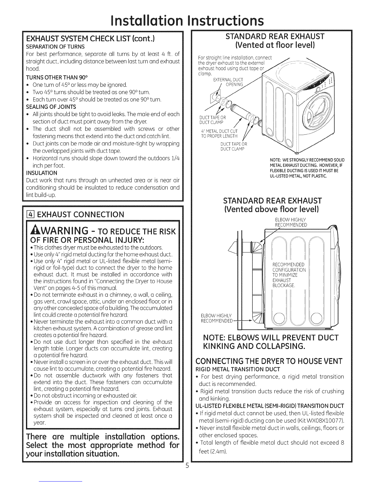
STANDARD REAR EXHAUST
(Vented atfloorlevel)
For straight line installation, connect
the dryer exhaust to the external
exhaust hood using duct tape or
clamp. EXTERNALDUCT
DUCT TAPEOR
DUCT CLAMP
4" METALDUCT CUT
TO PROPERLENGTH
DUCTTAPE OR
DUCTCLAMP
NOTE: WE STRONGLY RECOMMEND SOLID
METAL EXHAUST DUCTING. HOWEVER, IF
FLEXIBLEDUCTING ISUSED ITMUST BE
UL-LISTEDMETAL,NOT PLASTIC.
STANDARD REAR EXHAUST
(Vented above floorlevel)
ELBOWHIGHLY
RECOMMENDED-
ELBOWHIGHLY
RE_I If!
TOMINIMIZE _!1
EXHAUST: I,_,!i
BLOCKAGE. I I_l
i i I I i
NOTE: ELBOWS WILL PREVENT DUCT
KINKING AND COLLAPSING.
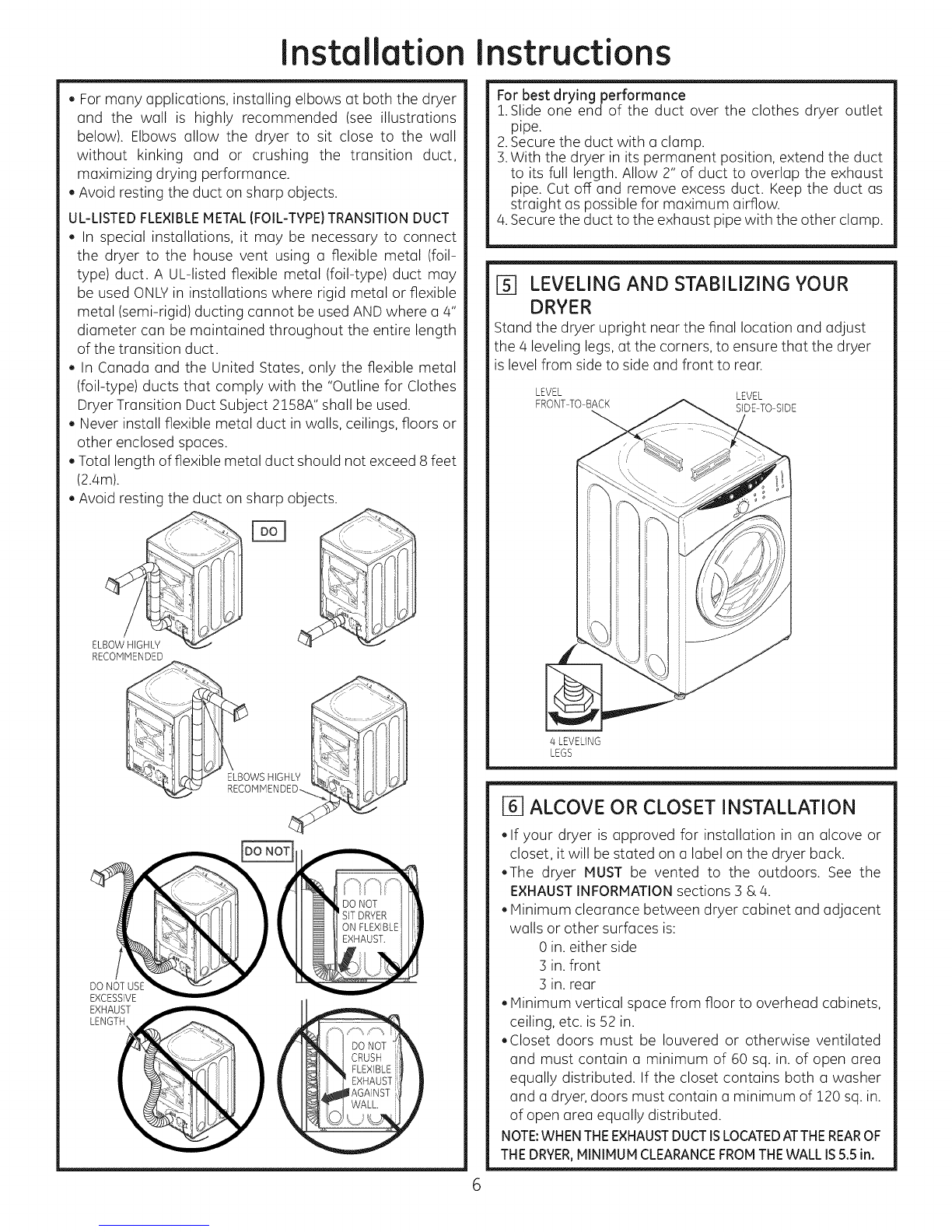
CONNECTING THE DRYERTO HOUSE VENT
RIGID METALTRANSITION DUCT
, For best drying performance, a rigid metal transition
duct isrecommended.
, Rigid metal transition ducts reduce the risk of crushing
and kinking.
UL-LISTEDFLEXIBLEMETAL (SEMI-RIGID}TRANSITIONDUCT
, If rigid metal duct cannot be used, then UL-listed flexible
metal (semi-rigid)ducting can be used (KitWXO8X10077).
, Never install flexible metal duct in walls, ceilings, floors or
other enclosed spaces.
, Total length of flexible metal duct should not exceed 8
feet (2.4m).