GE ARITECH FP400 Series User manual

FP400 Series
Conventional microprocessor
controlled fire detection and
alarm panels
Installation Manual
Version 2.3 / June 2004

2 FP400 Series Installation Manual
A
ritech is a GE Interlogix brand.
http://www.geindustrial.com/ge-interlogix/emea
© 2004 GE Interlogix B.V.. All rights reserved. GE Interlogix B.V. grants the right to reprint this manual for internal use only. GE
Interlogix B.V. reserves the right to change information without notice.

FP400 Series Installation Manual 3
CONTENTS
1Introduction............................................................................................................................................ 4
1.1 Package contents.......................................................................................................................... 4
1.2 Regulations ................................................................................................................................... 4
1.3 Compatibility.................................................................................................................................. 4
1.4 Series overview............................................................................................................................. 5
2Installation guide................................................................................................................................... 7
2.1 Installation ..................................................................................................................................... 7
2.2 Electrical connections ................................................................................................................... 8
2.3 Configuration............................................................................................................................... 14
2.4 Master modules........................................................................................................................... 16
3System start-up ................................................................................................................................... 17
3.1 System check.............................................................................................................................. 17
3.2 System power-up ........................................................................................................................ 17
3.3 Functional test............................................................................................................................. 17
4Maintenance......................................................................................................................................... 19
5Troubleshooting .................................................................................................................................. 20
6Technical specifications..................................................................................................................... 21

4 FP400 Series Installation Manual
1 INTRODUCTION
The range of FP400 fire alarm and detection panels has five models: FP402 of two
zones, FP404 of four zones, FP408 of eight zones, FP412 of twelve zones and FP416 of
sixteen zones.
The series has been designed to cover the needs of small to mid-sized installations such
as schools, homes, shops, small and medium-size businesses, etc.
1.1 Package contents
1 x Fire panel.
4.7K Ohm end-of-line resistors (one per zone plus one for each sounder output).
1 x 5x20 mm 2A fuse.
1 x 5x20 mm 1A fuse.
2 x Keys.
1 x Installation manual.
1 x User Guide.
1 x Multilingual language inserts sheet.
1 x Bridge connection for the batteries.
Check that the package contents are correct and in good condition before commencing
installation. If any defect exists repack the product and contact your distributor.
1.2 Regulations
This product must be installed by qualified personnel adhering to the EN-54
14 (UNE 23007-14) standard and any other applicable local authority laws.
This product has been designed according to EN54-2 and EN54-4 standards of 1997.
The EN54-2 standard includes some basic requirements and some optional ones. The
optional requirements this product meets are:
Subject Chapter Description
Indications 8.4 Notification of loss of all external power
Controls 7.11 Output delays
10 Test status indication
Outputs 7.8 Output for Fire alarm devices
1.3 Compatibility
This fire panel is compatible with all Aritech fire detectors and manual call points.
Compatibility with third party products cannot be guaranteed.

FP400 Series Installation Manual 5
1.4 Series overview
This conventional fire panel series has two different housing sizes:
Small size: for 2 or 4 zones (FP402 or FP404).
Large size: for 8, 12 or 16 zones (FP408, FP412 and FP416).
Figure 1: FP416 layout
Figure 2: FP404 layout
1
2 3
4
5
7
8
6
9
10
11
12
13
1
4
5 7
8
910
11
12
13
6
2 3

6 FP400 Series Installation Manual
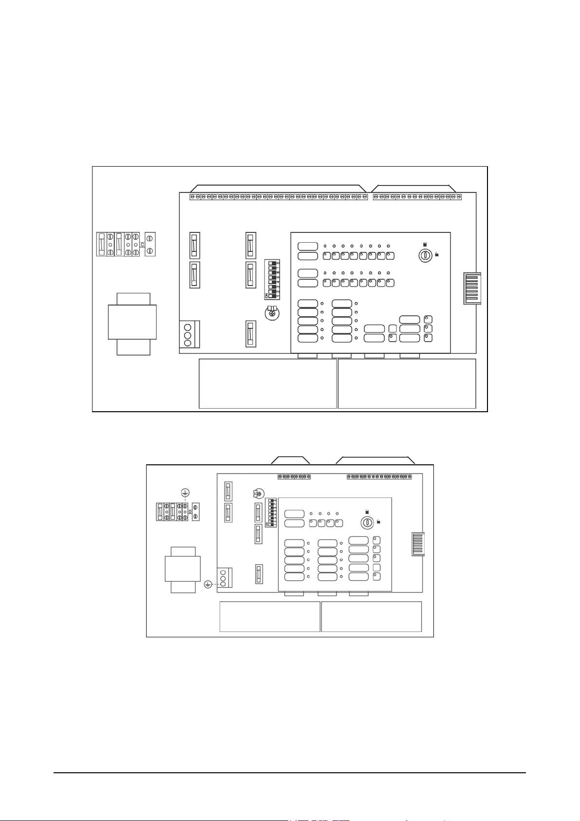
1. Mains connector (110 VAC / 230
VAC)
2. Zones connectors (from 2 to 4, or 8,
12 or 16, depending on fire panel
model)
3. Output connectors: Auxiliary 24 VDC,
Fire and Fault Relays and Sounders
4. 24V Resetable Output - 0.1 A fuse
5. Sounder output #1 - 0.3 A fuse
6. Auxiliary 24 VDC Output - 0.3 A fuse
7. Sounder output #2 - 0.3 A fuse
8. Configuration DIP switch
9. 5 A battery fuse
10.Transformer connector
11.Front panel connector
12.Master module output connector
13.24 V battery connector
Independent of the number of zones, all FP400 panels have the following common
functionality:
Enable / Disable per zone.
Test per zone.
Activation / Silencing of sounders.
Programming of sounder delays.
Supervision of main power, batteries and outputs.
Differentiation of manual call point and/or detector alarm signal within the same zone.
Remote reset optional operating mode.
Active end-of-line optional operating mode.
Relay master modules (optional)
Sounder master modules (optional)
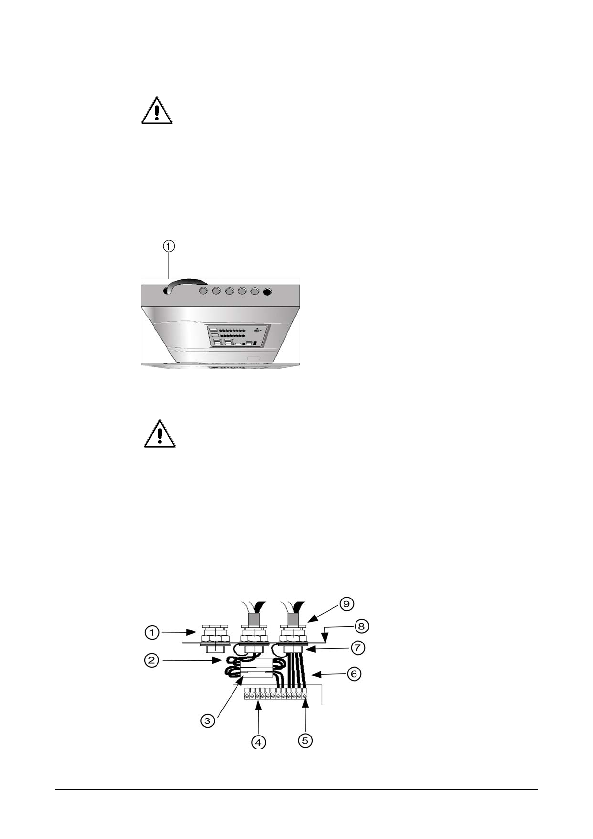
1.4.1 Inputs/Outputs
Figure 3: Inputs/outputs of FP400 fire panels
1. Zones input
2. Class change input.
3. Auxiliary 24 VDC output.
4. General alarm and fault relay (potential
free)
5. 24 VDC resetable output.
6. Two supervised 24 VDC sounder
outputs, with programmable delay.
1
23
4
5
6
+
Z1
Z2
Z3
Z1
CNONC
+ + ++ +
++
+
RFL
RFL
RFL

FP400 Series Installation Manual 7
2 INSTALLATION GUIDE
This product has been developed in compliance with the EN54-2 and UN54-4 (UNE
23007) standard and have approvals pending. It must be installed by qualified personnel,
taking into account the EN54-14 (UNE 23007-14) standard as well as the corresponding
local authority’s laws.
2.1 Installation
Remove the front cover from the panel before installation.
The panel must be installed in a clean, dry place free from vibrations with a temperature
between 5º and 40º C. The relative humidity must not exceed 95%. There should be no
condensation. The panel should be installed where the risk of fire is minimal and the
place is protected by the fire detection system. Risk of mechanical damage must be
avoided.
2.1.1 Fixing the panel to the wall
Fix the panel to the wall at an approximate height of 1.5 metres from the floor, in a place
with easy access. The Panel LED indicators should be at eye-level.
Create the cable holes you require in the panel before fixing it to the wall. Do
not perforate the panel in places other than those indicated. Avoid dropping
shavings or pieces of removed casing inside the panel as this may damage
the electronic circuits. PG11-type cable adapters may be used.
2.1.2 Selecting a language
The panel is designed for simple language selection and configuration.
Take the language sheet provided, select the appropriate language and cut out the
inserts along the pre-cut lines. Slide each insert into the relevant slot on the front of the
panel. See Figure 4 Insertion of language inserts.
The language sheet contains blank inserts for configuring additional
languages.
Figure 4: Insertion of language inserts

8 FP400 Series Installation Manual
2.2 Electrical connections
WARNING!
The 110 VAC or 230 VAC power must be connected to the power supply through an
external magneto-thermal switch.
The mains cable should have a minimum section of 1.5 mm².
To avoid possible short circuits and interference, the mains cable must be kept away
from the zone connection cables and from the communication ports.
Figure 5: Mains connection
1. In/out hole for mains power
To ensure ‘clean’ connections, the use of PG11-type cable adapters or seals
is recommended. In this way the cable is firmly fixed to the panel. The use of
pressure-sensitive flanges to fix the cables to the housing of the exchange is
also recommended.
If the system is exposed to a lot of electrical interference, the use of ferrite as close as
possible to the connection is recommended (see Figure 6 Example of a connection with
cable seal and ferrite).
Once the fire panel is mounted on the wall, the connecting of equipment may start. The
loops, the mains and the additional elements are connected to the base plate through the
holes on the top. The hole located away from the rest is for the mains.
Figure 6: Example of a connection with cable seal and ferrite
1. Cable adapter or seal
2. Screen connection to earth
3. Ferrite
4. Terminals
5. Connector socket
6. Cables
7. Nut
8. Fire panel metal frame
9. Input cable sleeve

FP400 Series Installation Manual 9
In installations with potential radio frequency interference, the use of a twisted, screened
cable is recommended. Connect the cable screen to the cable adapter and ensure that
the installation is properly connected to earth.
2.2.1 Mains power connection
Figure 7: Location of bipolar magneto-thermal switch
1. Bipolar magneto-thermal switch
Do not make any connections with the power supply on. Disconnect the
external magneto-thermal switch.
For safety, the sequence in which the connections are made must be:
1. Mains
2. Batteries.
The fire panel has two power supply systems: the main supply and the batteries.
Connecting to the mains supply
The fire panel must be connected to the main supply through a bipolar
magneto-thermal switch. An adequate ground connection is required. It is
recommended that the ground cable is longer than the rest so that, in case of
sudden pulling, it is the last cable to be disconnected.
For optimum fixation of the mains cable, use pressure-sensitive clamps on the housing.
2.2.2 Mains fuse
The fire panel may be powered from either 230 VAC or 110 VAC. Place the mains fuse in
its proper position (see Figure 8 Mains power connection).
To power from 110 VAC place the fuse in the left fuse holder.
To power from 230 VAC place the fuse in the right fuse holder.
See section 6 Technical specifications for fuse characteristics.
Do not use the mains fuse for connecting and disconnecting the fire panel from the
mains; use the magneto-thermal switch.

10 FP400 Series Installation Manual
Figure 8: Mains power connection
1. Mains fuse
2. Mains fuse
3. Neutral
4. Clamp
2.2.3 Connecting batteries
The FP400 panels require 2 x12 V batteries of 2.6 Ah for the FP402 and FP404, and 2 x
12 V 7 Ah for FP408, FP412 and FP416 respectively. These are connected in series in
order to obtain 24 VDC. A bridge connector for batteries is supplied in the box together
with the fire panel. Connect the positive contact (+) of one of the batteries to the negative
contact (-) of the other.
1. Place the batteries in the space reserved for them at the bottom of the fire panel box.
2. Connect the cables taking into account the colour correspondence (red positive, black
negative). Connect the battery bridge cable between the two batteries and the two
cables that come out of the fire panel to each of the batteries.
Figure 9: Battery connection

FP400 Series Installation Manual 11
2.2.4 Connecting zones
A zone output can only monitor a maximum of 20 detectors or 32 manual call
points. Every f zone has only one origin and one end. The last detector or call
point must therefore include a 4k7 Ohm end-of-line resistor. It is not allowed
to do T-offs of the line or place the end-of-line resistor in the zone output on
the main circuit board. Only if the zone is not going to be used it is necessary
to install an end-of-line resistor in the zone output.
Figure 10: Connecting a zone
2.2.5 Connecting detectors
This fire panel is compatible with all Aritech fire detectors. Compatibility with third party
products cannot be guaranteed. Refer to your product manual for more details.
Figure 11: Connecting detectors
1. Correct connection U2. Incorrect connection Y
3. Incorrect connection Y
Z1 +
+
+
Z2
End of line
resistor
4K7
Z
PK
sirena

12 FP400 Series Installation Manual
2.2.6 Connecting manual call points
This fire panel is compatible with all Aritech manual call points. Compatibility with third
party products cannot be guaranteed. Refer to your manual call point manual for more
information.
Some manual call points need a 100 Ohm 2W resistor in serial with the
normally open (NO) contact. This resistor avoids that a short-circuit is created
when the call point is activated, and allows the fire panel to identify the origin
of the alarm, differentiating it from the signal given by the detector. Refer to
your manual call point installation guide for further details.
If a dry contact is connected to a zone it is usually open (NO) and a 100 Ohm 2 W will be
connected in serial. This allows the fire panel to distinguish a detector alarm from a
manual call point alarm.
2.2.7 Class change input connection
This input allows the activation of the sounders from an external push-button. When a
short-circuit is created between these contacts, the sounders and/or bells will activate
until the short-circuit is removed. The push-button must be connected as normally open
(NO).
Figure 12: Class Change
2.2.8 Auxiliary 24 VDC output connection
Used to power auxiliary devices not included in a zone. It is protected with a fuse and the
maximum current allowed is 250 mA. It is not recommended to use this output to power
elements that have a certain current consumption in their standby mode.
Figure 13: Auxiliary supply Output
+
+

FP400 Series Installation Manual 13
2.2.9 Potential free relay output connection
These are outputs of potential free relays that can be activated in an alarm or fault
situation.
The fault output is generally energized.
Figure 14: Potential free relay output
2.2.10 Resetable 24 VDC output
This output allows the connection of devices that require to be reset from their power
connection (this is the case with the infra-red beams). This output has 24 VDC in stand-
by and when a reset is performed from the panel, the 24 VDC is disconnected for 3
seconds.
Figure 15: Resetable 24 VDC output
2.2.11 Connecting sounders and bells
The two sounder outputs on the PCB are identified as SND1 and SND2. Each of these
outputs allows for a supervised sounder circuit with a maximum consumption of 250 mA
per circuit.
It is required to use polarity sensitive sounders or to install a diode to prevent
sounders from being activated in standby condition.
C NO NC C NO NC
+

14 FP400 Series Installation Manual
Figure 16: Sounder outputs
The sounder output is activated and supplies 24 VDC when a zone alarm is activated due
to a detector or a manual call point. If a motorized alarm bell is used a diode may need to
be installed in parallel in order to avoid the effect of the inverted current
Figure 17: Sounder connections
1. Diode 2. EOL resistor
2.3 Configuration
2.3.1 Configuration of sounder delays
A DIP switch is located next to the keypad on the PCB for programming sounder delays
(see Figure 18 Location of configuration DIP switch). A sounder delay for up to a
maximum of 10 minutes can be programmed using DIP switches 1 to 4. See Figure 19
DIP switch sounder delay settings).
If a delay is programmed the Sounder Delay LED on the control panel is activated.
Figure 18: Location of configuration DIP switch
Sounder outputs
+ +
SND1 SND2

FP400 Series Installation Manual 15
1. DIP switch for sounder delay configuration
Any programmed delay will only be activated if the alarm is triggered by a
detector. An alarm triggered by a manual call point will never be delayed.
Figure 19 DIP switch sounder delay settings
1 minute delay 2 minute delay 3 minute delay 4 minute delay
5 minute delay 6 minute delay 7 minute delay 8 minute delay
9 minute delay 10 minute delay
Confirming sounder delay configuration
Use DIP switch 6 to confirm use of sounder delay mode.
Figure 20: Confirm delay configuration
Delay mode active Delay mode inactive
2.3.2 Configuration for active end-of-line resistors
You may activate either active end-of-line resistors or remote reset mode.
You may not activate both simultaneously.
An active end-of-line allows the panel to detect a fault caused by the removal of a
detector from the installation. This fault is indicated as an open circuit fault but the rest of
detectors in the installation keep working.
This operating mode is not compatible with the usual operating mode of a
conventional zone with “passive” end-of-line detection.
Besides configuring the fire panel, a schottky diode (BAT43) must be added to each of
the detector bases. This diode must be connected to the negative contact, whilst an
active end-of-line is installed the last detector of the zone line.
Use DIP switch 7 to activate this mode (see Figure 21 Active EOL configuration).

16 FP400 Series Installation Manual
Figure 21: Active EOL configuration
Active EOL active Active EOL inactive
Figure 22: Connection of a diode in an active end-of-line installation
The active end-of-line module is optional.
2.3.3 Configuration for remote reseting
You may activate either active end-of-line resistors or remote reset mode.
You may not activate both simultaneously.
Remote Reset mode changes the normal function of the class change input. If the class
change input is activated, then the reset will be activated. If the class change input
remains activated a fault is shown activating the fault relay.
Use DIP switch 8 to activate this mode (see Figure 23 Remote reset configuration).
Figure 23: Remote reset configuration
Remote reset active Remote reset inactive
2.4 Master modules
Two versions of the master module are available: a master module with 24 VDC outputs
and a master module with potential free relay outputs.
Refer to individual module installation guides for complete product features
and installation details.
Zone
Schottky
diode BAT43
A
ctive end–
of-line

FP400 Series Installation Manual 17
3 SYSTEM START-UP
3.1 System check
Before connecting the fire panel to the main power supply check the following
points.
The fire panel has been properly installed.
There is no short or open circuit in any of the zone lines.
All end-of-line resistors are installed (see section 2.2.4)
If manual call points have been installed, they have a resistor of 100 Ohm 2W in
series with their contacts (see section 2.2.6)
All required optional configurations (class change, potential free relays outputs,
auxiliary 24 VDC output) are all properly connected (see .
Sounder lines are properly connected with its polarity and with corresponding end-of-
line resistors of 4k7 Ohm. Program sounder delays as decided (see chapter 2.3.1)
The correct configuration of any special operating mode that has been programmed.
If no special mode is desired position all DIP switches to the OFF position.
Check that the mains power is either 230 VAC or 110 VAC using a tester. Place the
mains fuse accordingly. Check that the batteries have a voltage higher than 24 VDC.
3.2 System power-up
Once all connections and the installation have been verified, the fire panel can be
powered up in the following sequence:
1. Mains power.
2. Batteries.
At this time only the green service LED and (if programmed) the Sounder Delay LED
should be on. All other LED indicators should be off. If any other LED indicators are on
check your installation thoroughly before continuing.
3.3 Functional test
For a zone test, the fault simulations must be carried out by causing short-circuits and
opening the zone lines (to check the short and open circuit faults respectively).
The alarm simulation in the zone may be carried out by placing a resistor of 100 Ohm
2 W in parallel to the zone, or by activating a manual call point or detector.
Verify that when a fault is caused, the fault relay is activated.
Verify that when an alarm is raised, the alarm relay is activated immediately. After the
programmed delay, alarm sounders should also be activated.
If a class change input is used, its activation will activate the sounders as well.
A POWER SUPPLY FAULT WILL BE DELAYED BEFORE INDICATION.
Once the fire panel has been checked, it is advisable to perform a check on the
functionality of the detectors connected in the installation.

18 FP400 Series Installation Manual
The installer should activate all the detectors into alarm and ensure the system performs
all the operations and indications that were expected.

FP400 Series Installation Manual 19
4 MAINTENANCE
Maintenance measures recommended in EN54-14 must be adopted.
Maintenance to be performed by the installer or the maintenance company
Quarterly
Inspect the entries in the on-site register and the records of the control panel.
Implement the appropriate corrective action.
Check all battery connections and the battery voltages.
In every zone, check the alarm, faults and all auxiliary functions of the control and
signalling equipment.
Visually inspect the control and signalling equipment to detect any possible increase
in humidity and/or any other type of deterioration.
Check if there has been any structural alteration to the site that may affect the
functioning of the detectors, manual call points or sounders. If so, take the
appropriate action.
Any failure must be noted down in the on-site register book and the corrective action
taken as soon as possible.
Yearly
Place the control panel in “Test” and check the configuration of the system. Check
that all the detectors and manual call points work according to the manufacturer’s
specifications and programmed requirements.
Visually inspect all the equipment connections and make sure that they are securely
fastened, that they have not been damaged and that they are appropriately protected.
Examine and test all batteries.
Any defect must be noted down in the on-site register and the corrective action taken
as soon as possible

20 FP400 Series Installation Manual
5 TROUBLESHOOTING
Indication Cause Action
The service LED indicator is
OFF.
The panel has no power. Check power supply (110 or 230
VAC).
Check power supply fuse.
Check battery.
Check battery fuse.
The general fault and power
supply failure LED indicator is on
and the buzzer is sounding
intermittently.
The panel has no power supply
from the mains and is working
with batteries.
Check power supply (110 or 230
VAC).
Check power supply fuse.
Check transformer
Check battery connection.
Check battery fuse
Check that battery voltage is
above 24 VDC
Check battery charger voltage is
27.6 VDC
The system failure LED -
indicator is on and the buzzer is
sounding continuously.
Control panel failure. Restart the system
disconnecting the batteries and
the power supply voltage. After a
few seconds, reconnect the
power supply. If the problems
remain contact the supplier.
The general fault and
disconnection LED indicators are
on and the buzzer is sounding
intermittently.
The panel has no power supply
from the mains and the battery is
below 22 V (minimum working
voltage).
Disconnect the battery and the
power supply until the mains
voltage or charged batteries can
be supplied.
The general fault and zone
failure LED indicators are on
(flashing) and the buzzer is
sounding intermittently.
The indicated zone has a fault. Check the end-of-line resistance
of the zone (4k7).
Check that there are no short or
open circuits in the lines.
Check that there are no inverted
polarity detector connections.
Check that there are no manual
call points activated without a
series resistance.
The general disabled and zone
disabled LED indicators are on
and the buzzer is sounding
intermittently.
The indicated zone is disabled. If you wish to enable, turn the
key to the ON position and press
the key of the disabled zone.
The panel does not respond to
the keypad.
The keypad is disabled. To enable the keypad, turn the
key to the ON position.
Other manuals for ARITECH FP400 Series
1
Table of contents
Popular Firefighting Equipment manuals by other brands

Cooper Lighting Solutions
Cooper Lighting Solutions HALO H450FR2ICATD010 instructions

Waterous
Waterous Aquis Foam Manager Operation and maintenance manual

FireWare
FireWare Silver Fire Manikin user manual

Waterous
Waterous AQUIS Series Installation, operation and maintenance instructions

ZURN
ZURN PEX installation instructions

Tyco
Tyco EC-11 Series quick guide