LOGIQ 7/LOGIQ 7 Pro Quick Guide Direction 5307393-100 Rev. 1 3
Preparing for an Exam
Starting an Exam
New Patient
To start a new patient’s exam,
1. Press Patient. Press the New Patient button on the
Patient menu.
2. Select the Exam Category.
3. Type the Patient ID, Patient Name, Birthdate, etc.
4. Press the Register button on the Patient menu (DO
NOT press Register if you are automatically
generating a patient ID).
5. Press Scan, B-Mode, Esc, or Exit. Select the probe
from the Touch Panel.
Probe Selection
Select a probe from the Touch Panel (the system
automatically selects the last-used application for this
probe).
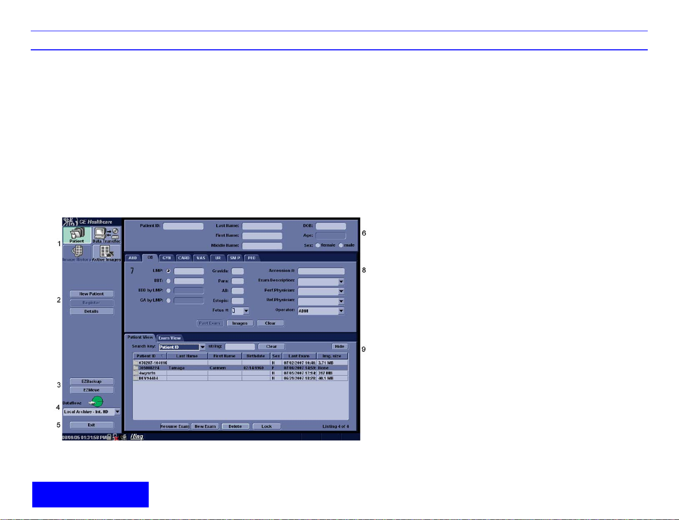
Patient Entry Menu
Image Management Window [1]
Access to this patient’s exam history and image
management features.
Function Selection Window [2]
New Patient is used to clear the patient entry screen to
input a new patient’s data into the database. Register is
used to enter new patient information into the database
prior to the actual exam being performed.Details displays
exam details and additional patient information.
EZ Backup/EZMove [3]
One-step method to backup (move and delete patient
images) to an external media.
Dataflow [4]
Selects this exam’s dataflow preference.
Exit [5]
Exits the Patient Menu and returns to scanning.
Patient Information [6]
Patient ID, Name, Birthdate, Age and Sex.
Category Selection and Exam Information [7&8]
Select the appropriate category and enter the exam
information.
Patient View and Exam View [9]
Patient View lists the patients in the database. “Search
key” enables searching list by Patient ID, Last Name,
First Name, Birthdate, Sex and Last Exam date. “Search
string” and “Search from” fields help define the search
parameters.
Exam View lists the exams of the selected patient. Select
the patient or the exam in Patient View and press “Exam
View” or “Review”.