GE JX9152 User manual

Installation Microwave Oven
Instructions Built-In Trim Kits
1
BEFORE YOU BEGIN
Read these instructions completely and carefully.
•IMPORTANT ³Save these instructions
for local inspector’s use.
•IMPORTANT ³Observe all governing codes and
ordinances.
• Note to Installer – Be sure to leave these instructions with
the Consumer.
• Note to Consumer – Keep these instructions for future
reference.
• Skill level – Installation of this appliance requires basic
mechanical and electrical skills.
• Completion time – 1 to 3 hours
• Proper installation is the responsibility of the installer.
• Product failure due to improper installation is not covered
under the Warranty.
• This kit is for use on models:PEB9159DJ, PEB9159SJ,
PEB9159EJ and CEB1599SJ.
• This kit and microwave are approved for installation alone
or above any single electric wall oven. Do not mount
adjacent (within 2 feet) to any range, cooktop, gas oven, or
other microwave.
• This product is to be installed 3 feet above floor level.
• Do not alter or modify any part of this kit or the oven.
• For easier installation and personal safety, we
recommend that two people install this microwave oven.
• Unplug the microwave oven before attempting installation
of this kit.
WARNING
³This oven must be plugged into a
properly grounded 3-hole, 120 volt receptacle as required by
the National Electrical Code.
WARNING
³Before beginning the installation,
switch power off at service panel and lock the service
disconnecting means to prevent power from being switched
on accidentally. When the service disconnecting means
cannot be locked, securely fasten a prominent warning
device, such as a tag, to the service panel.
Questions? Call GE Answer Center at 800.626.2000 or Visit our Website at: GEAppliances.com
PARTS INCLUDED
NOTE: This kit has extra screws to prevent the technician
from spending extra time locating a replacement in case
they lose one during installation.
JX9152 and JX9153
PART QUANITY
Rear Duct 1
Bottom Duct
1
Trim Kit
Frame 1
Rail 2
Short Screws 15 required
1 extra
Long Wood
Screws 4 required
2 extra

CUTOUT DIMENSIONS
WARNING
³This trim kit uses air flow from the top, bottom and
sides of the trim frame. Blocking the air flow can cause
the microwave to function improperly and may cause
damage to the microwave.
Allow a 1” clearance beyond the edge of the trim
frame to provide proper air flow.
FOR INSTALLATION ABOVE A BUILT-IN OVEN:
Microwave oven should be installed on a 3/8” plywood
base and supported by 2x4 or 1x2 equivalent runners
on all sides. Base must be capable of supporting a
minimum of 100 lbs.
2
Installation Instructions
Min. depth with receptacle outside cutout – 16
”
Min. depth with receptacle inside cutout – 18
”
120 volt – 60 Hertz grounded power receptacle.
TOOLS YOU WILL NEED
❒
2 Phillips Screwdrivers (#1 & #2)
❒
Drill with 3/32” Drill Bit
❒
Pencil
❒
Level
❒
Tape Measure
Depth
Height
1” Overlap
Width
1” Overlap
1” Clearance beyond
trim frame
(on all sides)
3” Min.
27”models: 1 7/8” overlap
30”models: 3 5/16” overlap
Bottom of trim kit must be
minimum of 36” from floor
Dimension Trim Kit Cutout
27” 30”
Height 19 1/8” 19 1/8” 17 1/16 ± 1/16”
Width 26 7/8” 29 3/4” 23 1/8± 1/16”
GROUNDING INSTRUCTIONS
This appliance must be grounded. In the event of an
electrical short circuit, grounding reduces the risk
of electric shock by providing an escape wire for
the electric current. This appliance is equipped with
a cord having a grounding wire with a grounding
plug. The plug must be plugged into an outlet
that is properly installed and grounded.Consult a
qualified electrician or serviceman if the grounding
instructions are not completely understood, or if
doubt exists as to whether the appliance is properly
grounded.
Improper use of
the grounding plug
can result in a risk of
electric shock.
Do not use an
extension cord. If the
power supply cord
is too short, have a
qualified electrician
or serviceman install
an outlet near the
appliance.
Permanent and Correct Installation
3-Prong plug
Grounding pin
3-Prong receptacle
Grounded receptacle box
WARNING
ELECTRICAL REQUIREMENTS
Product rating is 120 volts AC, 60 Hertz, 14
amps and 1.60 kilowatts. This product must be
connected to a supply circuit of the proper voltage
and frequency. Wire size must conform to the
requirements of the National Electrical Code or the
prevailing local code for this kilowatt rating. The
power supply cord and plug should be brought to
a separate 15 to 20 ampere branch circuit single
grounded outlet. The outlet box should be located
in the cabinet above the oven. The outlet box and
supply circuit should be installed by a qualified
electrician and conform to the National Electrical
Code or the prevailing local code.

2
INSTALL THE RAILS
Disconnect the microwave oven from the receptacle.
Remove everything out of the microwave oven, including
packing, Owner’s Manuals, turntable and turntable support.
A protective film has been applied to some microwave
oven and trim kits. If applied, remove the film. Turn over the
microwave oven and secure the rails to oven Base Plate
by inserting 4 screws (A). Be careful not to scratch the
microwave oven.
1
LOCATE AND INSTALL THE BASE PAN
Set Base Pan into the front cabinet microwave oven
cutout and center it right and left. Push back until the
front flange is against the cabinet front wall. Mount
the Base Pan using 3 screws (A).
3
Installation Instructions
Screw A
Microwave
Oven Bottom
Rail Screw (A)
Flanges Door
Base Plan
Mounting Holes
3
INSTALL THE REAR DUCT
1. Gently return microwave oven to its upright position.
2. Remove screw A.
3. Align the rear duct with the back of microwave oven, as
shown.
4. Slide two tabs into the slots on the right side of the back
of microwave oven.
5. Use two short screws to secure top of rear duct to the
back of microwave oven, as shown.
A. Rear duct tabs
B. Slots
A B
A. Short screws (2)
B. Rear duct
C. Back of microwave oven
ABC
Screw A

7
INSTALL THE TRIM KIT FRAME
1. Position the assembled Trim Kit frame around the
oven.
2. Drill pilot holes using the drill (3/22).
3. Secure the Trim Kit by four screws (B) through the trim
kit into the cabinet by using a manual screw driver.
IMPORTANT-
³Start all screws before tightening any one screw. Do
not overtighten screws since it can cause misalignment of
top/side strips.
DE68-03364A
49-40762 4
Installation Instructions
11-15 GE
Printed in China
Screw B
READ CAREFULLY. KEEP THESE INSTRUCTIONS.
8
REPLACE ANY LOOSE ITEMS
1. Your trim kit is now fully installed. Replace the
turntable and turntable support that was removed
from inside the microwave oven.
2. Keep these installation instructions and extra screws
for future reference and need. Do not place them in
the microwave oven.
3. Replace the house fuse, or close the circuit breaker to
restore power at the service panel.
6
SECURE THE RAILS TO THE CABINET
Ensure the Base Pan and Bottom Bracket front flanges are
tight against the cabinet, and that the screws holes are
aligned. Drive 4 screws (A) through the Base Pan and Rails
into the cabinet
Screw A
Mounting Holes
4
INSTALL THE MICROWAVE OVEN
Plug the power cord into the wall receptacle. Slide the
microwave oven assembly gently into the cabinet, using
care not to pinch the power cord. Be sure to keep the
assembly centered as it slides back to where the tongue of
the rails goes through the slots on Base Plan. The top edges
of the Base Plan should now be centered right to left in the
opening. The Base should be tight against the cabinet.
5
CHECK LEVELING
Check the leveling by placing a level at the front and sides
of the microwave. It may be necessary to add wood shims
under the base pan to level the microwave front-to-back
and side-to-side.
Rail
Guides
Rails
3
INSTALL THE REAR DUCT (continues)
6. Use three short screws to secure back of rear duct to the
back of microwave oven, as shown.
A. Short screws (3)
B. Rear duct
C. Back of microwave oven
ABC

Instrucciones Kits de Horno Microondas con
de Instalación Terminaciones Incorporadas
1
❒
ANTES DE COMENZAR
Lea estas instrucciones en su totalidad y atentamente.
•IMPORTANTE ³Conserve estas instrucciones
para uso del inspector local.
•IMPORTANTE³Cumpla con todos los códigos y
ordenanzas gubernamentales.
• Nota para el Instalador – Asegúrese de que el
Comprador conserve estas instrucciones.
• Nota para el Comprador – Conserve estas instrucciones
para referencia futura.
• Nivel de habilidad – La instalación de este
electrodoméstico requiere un nivel básico de habilidades
mecánicas y eléctricas.
• Tiempo de instalación – entre 1 y 3 horas
• La correcta instalación del producto es responsabilidad
del instalador.
• Si se producen fallas en el producto debido a una
instalación inadecuada, la Garantía no cubrirá las
mismas.
• Este kit es para uso en los modelos: PEB9159DJ,
PEB9159SJ, PEB9159EJ y CEB1599SJ.
• El kit y el horno microondas están aprobados para su
instalación en forma aislada o sobre cualquier horno
eléctrico de pared simple. No monte el mismo de forma
adyacente (dentro de los 2 pies) a cualquier cocina,
superficie de cocción, horno a gas, u otro microondas
• Este producto se deberá instalar a 3 pies de distancia del
piso.
• No altere ni modifique ninguna parte de este kit o del
horno.
• Para una instalación más fácil y por cuestiones de
seguridad personal, recomendamos que la instalación del
horno microondas sea realizada por dos personas.
• Desenchufe el horno microondas antes de intentar
instalar este kit.
ADVERTENCIA
³Este horno deberá estar
correctamente enchufado en un
receptáculo de 3 agujeros y 120V, de acuerdo con lo
requerido por el Código de Electricidad Nacional (National
Electrical Code).
ADVERTENCIA
³Antes de comenzar con la instalación,
apague el interruptor del panel del
servicio y bloquee el suministro del servicio a fin de evitar
que la corriente se active en forma accidental. Cuando el
suministro del servicio no pueda ser bloqueado, ajuste de
forma segura un dispositivo de advertencia visible, tal como
una etiqueta, al panel del servicio.
¿Preguntas? Llame a 800.GE.CARES (800.432.2737) o Visite nuestro sitio web en: GEAppliances.com
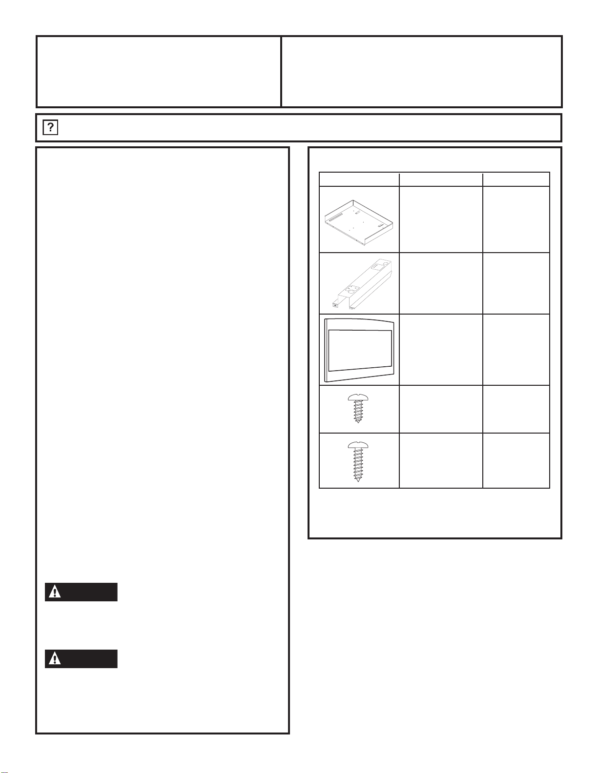
PIEZAS INCLUIDAS
PIEZA CANTIDAD
❒ Olla de la Base 1
❒ Riel 2
❒ Kit de 1
Terminaciones
❒ Tornillo A de 11 requeridos
4 mm. x 10 mm. 3 adicionales
❒ Tornillo B de 4 requeridos
4 mm. x 16 mm 2 adicionales
NOTA: Este kit cuenta con tornillos adicionales a fin de
evitar que el técnico necesite tiempo adicional para ubicar
un tornillo de reemplazo durante la instalación.
JX827 and JX830

❒ 1
UBIQUE E INSTALE UNA OLLA DE LA
BASE
Coloque la Olla de la Base en la abertura del gabinete
frontal del horno microondas y centre la misma sobre
la derecha y la izquierda. Empuje hacia atrás hasta
que la pestaña frontal quede contra la pared frontal
del gabinete. Monte la Olla de la Base usando 3
tornillos (A).
❒ ❒ DIMENSIONES DE LA ABERTURA
ADVERTENCIA ³Este kit con terminación
usa el flujo de aire desde la parte superior, inferior o los
costados de la estructura con terminación. Bloquear el flujo
de aire puede hacer que el microondas funcione de forma
inadecuada y ocasionar daños sobre el mismo.
Deje un espacio de 1” más allá del extremo de la estructura
con terminación para brindar el flujo de aire apropiado.
PARA LA INSTALACIÓN SOBRE UN HORNO EMPOTRABLE:
El horno microondas debería ser instalado en una base de
contrachapado de 3/8” y contar con el soporte de tirantes
equivalentes de 2 x 4 o 1 x 2 en todos los costados. La base
deberá poder soportar un mínimo de 100 libras.
2
Instrucciones de Instalación
Profundidad mínima con el receptáculo fuera de la abertura – 16”
Profundidad mínima con el receptáculo dentro de la abertura – 18”
Receptáculo de corriente con conexión a tierra, 120 voltios, 60 Hertz
Tornillos
A
HERRAMIENTAS QUE NECESITARÁ
❒
2 Destornilladores Phillips (nº 1 y nº 2))
❒
Agujeree con una broca de 3/32”
❒
Punzón o clavo
❒
Lápiz
❒
Cuchillo
❒
Nivel
❒
Cinta métrica
Profundidad
Altura
Superposición
de 5/8”
Ancho
Superposición de 7/8”
Despeje de 1” más allá de la
estructura con terminación
(hacia todos los lados)
Mín. de 3”
Modelos de 27”:
Superposición de 1”
Modelos de 30”:
Superposición de 2 1/2
”
La parte inferior del kit con terminación deberá
tener un mínimo de 36” desde el piso
Dimensión Kit de Terminaciones Abertura
27” 30”
Altura 16
1/2” 16 1/2” 15 ± 1/16”
Ancho 26 7/8” 29 7/8” 24 7/8± 1/16”
Olla de la Base
Agujeros de Montaje

❒ 3
INSTALE EL HORNO MICROONDAS
Enchufe el cable de corriente en el tomacorriente. Deslice
el ensamble del horno microondas al gabinete de forma
cuidadosa, teniendo cuidado de que no haya pellizcos
sobre el cable de corriente. Asegúrese de mantener el
ensamble centrado a medida que se vuelve a deslizar hacia
las lengüetas de los rieles a través de las ranuras de la Olla
de la Base. Los extremos superiores de la Olla de la Base
deberían ahora estar centrados de derecha a izquierda en la
abertura. La Base debería estar ajustada contra el gabinete.
❒ 2INSTALACIÓN DE LOS RIELES
Desconecte el horno microondas del receptáculo. Retire
todo lo que haya dentro del horno microondas, incluyendo
el embalaje, Manuales del Propietario, el plato giratorio y el
soporte del plato giratorio. Se aplicó una película protectora
en algunos hornos microondas y kits con terminaciones. Si
cuenta con la misma, retire la película. Dé vuelta el horno
microondas y asegure los rieles a la Placa de la Base del
horno, insertando 4 tornillos (A). Asegúrese de no rayar el
horno microondas.
3
Instrucciones de Instalación
❒ 5
ASEGURE LOS RIELES AL GABINETE
Asegure que la Olla de la Base y las lengüetas frontales
del Soporte Inferior estén ajustadas contra el gabinete, y
que los agujeros de los tornillos estén alineados. Coloque 4
tornillos (A) a través de la Olla de la Base y los Rieles sobre el
gabinete.
Tornillo A
❒ 4
CONTROL DE LA NIVELACIÓN
Controle la nivelación colocando un nivel en el frente y
los costados del horno microondas. Es posible que sea
necesario agregar cuñas de madera debajo de la olla de
la base para nivelar el frente del microondas con la parte
trasera o un costado con el otro.
Parte Inferior del
Horno Microondas
Riel Tornillo (A)
Pestañas Puerta
Riel
Guías
Rieles
Agujeros de Montaje

❒ 6INSTALACIÓN DE LA ESTRUCTURA
DEL KIT CON TERMINACIONES
A
Posicione la estructura ensamblada del Kit con
Terminaciones alrededor del horno.
B
Asegure el Kit con Terminaciones colocando cuatro
tornillos (B) a través del kit con terminaciones en el
gabinete.
PRECAUCIÓN ³Ubique todos los tornillos
antes de comenzar a ajustar el primero. No ajuste en
exceso los tornillos, ya que esto podrá ocasionar
desalineaciones de las tiras superiores/ laterales.
DE68-03364A
49-40762
4
Instrucciones de Instalación
03-16 GE
Impreso en China
Screw B
LEA DETENIDAMENTE. CONSERVE ESTAS INSTRUCCIONES.
❒ 7
REEMPLACE CUALQUIER ÍTEM FLOJO
A
Su kit con terminación se encuentra ahora
completamente instalado. Reemplace el plato giratorio
y su soporte correspondiente, que fueron retirados del
interior del horno microondas.
B
Guarde estas instrucciones de instalación y tornillos
adicionales para referencia y uso futuro. No los
coloque en el horno microondas.
C
Reemplace el fusible del hogar o cierre el disyuntor
para reiniciar la corriente en el panel del servicio.
Tornillo A
Table of contents
Languages:
Other GE Microwave Oven manuals

GE
GE JEM4JW Use and care manual

GE
GE JVM1790BK - Profile 1.7 cu. Ft. Convection... User manual

GE
GE Profile PVM1790 User manual

GE
GE Spacemaker JVM1540 User manual

GE
GE AVM4160DFBS Manual

GE
GE Spacemaker II JEM31G Installation instructions

GE
GE Spacemaker JVM1750DMBB Manual

GE
GE JE1445G Installation instructions

GE
GE AVM4160 User manual

GE
GE SpacemakerXL JVM1320 User manual

GE
GE JES922T Use and care manual

GE
GE JE1456L User manual

GE
GE Spacemaker JVM1730 User manual

GE
GE JE740DRBB Manual

GE
GE JVM1490BH User manual

GE
GE JVM6175 User manual

GE
GE spacemaker III User manual

GE
GE Spacemaker 164D2092P020 User manual

GE
GE JE1415 Installation instructions

GE
GE SpacemakerXL JVM1440WA User guide