GE DEH-40117 User manual

Installer Instructions
WARNING: FF
FFaa
aaii
iilllluu
uurr
rree
ee tt
ttoo
oo ff
ffoo
oolllllllloo
ooww
ww tt
tthh
hhee
eess
ssee
ee ii
iinn
nnss
sstt
ttrr
rruu
uucc
cctt
ttii
iioo
oonn
nnss
ss cc
ccoo
oouu
uulllldd
dd
rr
rree
eess
ssuu
uulllltt
tt ii
iinn
nn dd
ddee
eeaa
aatt
tthh
hh,,,, pp
ppee
eerr
rrss
ssoo
oonn
nnaa
aallll ii
iinn
nnjjjjuu
uurr
rryy
yy,,,, oo
oorr
rr pp
pprr
rroo
oopp
ppee
eerr
rrtt
ttyy
yy dd
ddaa
aamm
mmaa
aagg
ggee
ee....
••
•• TT
TThh
hhii
iiss
ss cc
ccii
iirr
rrcc
ccuu
uuii
iitt
tt bb
bbrr
rree
eeaa
aakk
kkee
eerr
rr ii
iiss
ss ii
iinn
nntt
ttee
eenn
nndd
ddee
eedd
dd ff
ffoo
oorr
rr uu
uuss
ssee
ee oo
oonn
nn ss
ssii
iinn
nngg
ggllllee
ee----
pp
pphh
hhaa
aass
ssee
ee gg
ggrr
rroo
oouu
uunn
nndd
ddee
eedd
dd,,,, 11
1122
2200
00 VV
VVaa
aacc
cc 22
22----ww
wwii
iirr
rree
ee bb
bbrr
rraa
aann
nncc
cchh
hh cc
ccii
iirr
rrcc
ccuu
uuii
iitt
ttss
ss....
••
•• UU
UUss
ssee
ee oo
oonn
nnllllyy
yy cc
ccaa
aabb
bbllllee
ee hh
hhaa
aavv
vvii
iinn
nngg
gg tt
ttww
wwoo
oo cc
ccoo
oonn
nndd
dduu
uucc
cctt
ttoo
oorr
rrss
ss pp
pplllluu
uuss
ss gg
ggrr
rroo
oouu
uunn
nndd
dd,,,,
ss
ssuu
uucc
cchh
hh aa
aass
ss NN
NNMM
MM----BB
BB cc
ccaa
aabb
bbllllee
ee....
••
•• DD
DDoo
oo NN
NNOO
OOTT
TT uu
uuss
ssee
ee cc
ccaa
aabb
bbllllee
ee hh
hhaa
aavv
vvii
iinn
nngg
gg tt
tthh
hhrr
rree
eeee
ee cc
ccoo
oonn
nndd
dduu
uucc
cctt
ttoo
oorr
rrss
ss pp
pplllluu
uuss
ss
gg
ggrr
rroo
oouu
uunn
nndd
dd....
••
•• DD
DDoo
oo nn
nnoo
oott
tt uu
uuss
ssee
ee tt
tthh
hhee
ee bb
bbrr
rree
eeaa
aakk
kkee
eerr
rr oo
oonn
nn aa
aa ss
sshh
hhaa
aarr
rree
eedd
dd----nn
nnee
eeuu
uutt
ttrr
rraa
aallll cc
ccii
iirr
rrcc
ccuu
uuii
iitt
tt....
••
•• TT
TThh
hhii
iiss
ss ee
eeqq
qquu
uuii
iipp
ppmm
mmee
eenn
nntt
tt mm
mmuu
uuss
sstt
tt bb
bbee
ee ii
iinn
nnss
sstt
ttaa
aallllllllee
eedd
dd aa
aann
nndd
dd ss
ssee
eerr
rrvv
vvii
iicc
ccee
eedd
dd oo
oonn
nnllllyy
yy
bb
bbyy
yy aa
aa qq
qquu
uuaa
aallllii
iiff
ffii
iiee
eedd
dd ee
eellllee
eecc
cctt
ttrr
rrii
iicc
ccii
iiaa
aann
nn....
WARNING: TT
TTuu
uurr
rrnn
nn oo
ooff
ffff
ff pp
ppoo
ooww
wwee
eerr
rr tt
ttoo
oo mm
mmaa
aaii
iinn
nn bb
bbrr
rree
eeaa
aakk
kkee
eerr
rr bb
bbee
eeff
ffoo
oorr
rree
ee
bb
bbee
eegg
ggii
iinn
nnnn
nnii
iinn
nngg
gg ii
iinn
nnss
sstt
ttaa
aallllllllaa
aatt
ttii
iioo
oonn
nn.... FF
FFaa
aaii
iilllluu
uurr
rree
ee tt
ttoo
oo dd
ddoo
oo ss
ssoo
oo ww
wwii
iillllllll rr
rrii
iiss
sskk
kk ee
eellllee
eecc
cctt
ttrr
rrii
iicc
ccaa
aallll
ss
sshh
hhoo
oocc
cckk
kk aa
aann
nndd
dd pp
ppoo
ooss
ssss
ssii
iibb
bbllllee
ee dd
ddee
eeaa
aatt
tthh
hh,,,, pp
ppee
eerr
rrss
ssoo
oonn
nnaa
aallll ii
iinn
nnjjjjuu
uurr
rryy
yy,,,, oo
oorr
rr pp
pprr
rroo
oopp
ppee
eerr
rrtt
ttyy
yy
dd
ddaa
aamm
mmaa
aagg
ggee
ee....
Install the Arc-Fault Circuit Breaker using the following
procedure:
1. Latch the Arc-Fault Circuit Breaker by moving its
handle firmly to the OFF position.
2. Wire the Arc-Fault Circuit Breaker to load center (see
connection diagram).
A. Connect the coiled white “pigtail” wire from the Arc-
Fault Circuit Breaker to the panel or enclosure
neutral bus terminal and secure it tightly. Uncoil
pigtail as necessary.
B. Connect the white (neutral) load wire to the
terminal side of the circuit breaker, identified by a
silver-colored terminal screw, labeled LOAD
NEUTRAL.
C. Connect black (hot) wire to circuit breaker
terminals labeled LOAD, identified by a gold-
colored screw terminal screw.
3. Plug the circuit breaker into the desired pole position.
4. Test the Arc-Fault Circuit Breaker using the white
rocker switch on the front of the breaker, labeled TEST.
Follow Test Procedures as indicated in next section.
5. See Troubleshooting Guide for the troubleshooting
method to be used for a tripped Arc-Fault Circuit
Breaker.
CAUTION:::: DD
DDoo
oo nn
nnoo
oott
tt rr
rree
eevv
vvee
eerr
rrss
ssee
ee----ff
ffee
eeee
eedd
dd oo
oorr
rr bb
bbaa
aacc
cckk
kk----ww
wwii
iirr
rree
ee.... DD
DDoo
oo nn
nnoo
oott
tt ss
ssuu
uubb
bbjjjjee
eecc
cctt
tt tt
ttoo
oo mm
mmee
eegg
gggg
ggee
eerr
rr,,,, hh
hhii
iigg
gghh
hh----vv
vvoo
oolllltt
ttaa
aagg
ggee
ee,,,, oo
oorr
rr hh
hhii
iigg
gghh
hh----pp
ppoo
oott
tt tt
ttee
eess
sstt
ttss
ss.... RR
RRee
eemm
mmoo
oovv
vvee
ee tt
tthh
hhee
ee
cc
ccii
iirr
rrcc
ccuu
uuii
iitt
tt bb
bbrr
rree
eeaa
aakk
kkee
eerr
rr bb
bbee
eeff
ffoo
oorr
rree
ee hh
hhii
iigg
gghh
hh----pp
ppoo
oott
tttt
ttii
iinn
nngg
gg oo
oocc
cccc
ccuu
uurr
rrss
ss oo
oonn
nn tt
tthh
hhee
ee cc
ccii
iirr
rrcc
ccuu
uuii
iitt
tt oo
oorr
rr tt
tthh
hhee
ee ss
ssyy
yyss
sstt
ttee
eemm
mm....
Test Procedures (Circuit breaker should be tested regularly, at least once per month.)
The Arc-Fault Circuit Breaker senses arcs in two different ways. The test feature allows the homeowner to test each of
these modes by depressing a rocker switch in two directions. The breaker has passed the test if the TRIP flag appears in
the window.
1. Arc Test: Rotate the test switch in the “Arc Test” direction to check the ability of the Arc-Fault Circuit Breaker to
detect arcing from phase to neutral (above normal levels needed to run appliances).
2. Short Test: Rotate the test switch in the “Short Test” direction to check the ability of the Arc-Fault Circuit Breaker to
detect low level arcs from phase to ground.
CAUTION
::::
TT
TThh
hhee
ee AA
AArr
rrcc
cc----FF
FFaa
aauu
uulllltt
tt CC
CCii
iirr
rrcc
ccuu
uuii
iitt
tt BB
BBrr
rree
eeaa
aakk
kkee
eerr
rr mm
mmuu
uuss
sstt
tt bb
bbee
ee ss
ssuu
uupp
pppp
ppllllii
iiee
eedd
dd ww
wwii
iitt
tthh
hh pp
ppoo
ooww
wwee
eerr
rr ff
ffrr
rroo
oomm
mm tt
tthh
hhee
ee lllloo
ooaa
aadd
dd cc
ccee
eenn
nntt
ttee
eerr
rr ii
iinn
nn oo
oorr
rrdd
ddee
eerr
rr ff
ffoo
oorr
rr tt
tthh
hhee
ee tt
ttee
eess
sstt
ttss
ss tt
ttoo
oo
ff
ffuu
uunn
nncc
cctt
ttii
iioo
oonn
nn pp
pprr
rroo
oopp
ppee
eerr
rrllllyy
yy.... II
IIff
ff tt
tthh
hhee
ee pp
ppoo
ooww
wwee
eerr
rr ii
iiss
ss oo
oonn
nn aa
aann
nndd
dd ee
eeii
iitt
tthh
hhee
eerr
rr oo
ooff
ff tt
tthh
hhee
eess
ssee
ee tt
ttee
eess
sstt
tt ff
ffaa
aaii
iillll tt
ttoo
oo tt
ttrr
rrii
iipp
pp,,,, tt
tthh
hhee
ee AA
AArr
rrcc
cc----FF
FFaa
aauu
uulllltt
tt CC
CCii
iirr
rrcc
ccuu
uuii
iitt
tt BB
BBrr
rree
eeaa
aakk
kkee
eerr
rr mm
mmaa
aayy
yy bb
bbee
ee uu
uunn
nnaa
aabb
bbllllee
ee tt
ttoo
oo
dd
ddee
eett
ttee
eecc
cctt
tt aa
aarr
rrcc
ccss
ss.... TT
TThh
hhee
ee cc
ccii
iirr
rrcc
ccuu
uuii
iitt
tt bb
bbrr
rree
eeaa
aakk
kkee
eerr
rr ii
iiss
ss dd
ddee
eeff
ffee
eecc
cctt
ttii
iivv
vvee
ee aa
aann
nndd
dd ss
sshh
hhoo
oouu
uulllldd
dd bb
bbee
ee rr
rree
eepp
ppllllaa
aacc
ccee
eedd
dd....
DEH 40117 Homeowner & Installer Information
Arc-Fault Circuit Breaker, One-Pole
g
Arc-Fault Circuit Breaker Connection Diagram
120Vac
Duplex
Receptacle
Load
Power
Wire
(Black)
Arc-Fault
Circuit
Breaker
Load
Neutral
Wire
(White)
CoiledWhite
Wire Connects to
Load Center Neutral

Troubleshooting Guidelines
Condition Potential Cause Solution/Action
Push-to-test
switch will
not trip
circuit
breaker.
1. Circuit breaker is OFF.
2. Circuit breaker is tripped.
3. Load center is not energized.
4. Load center neutral pigtail) is not
connected to the neutral bus bar.
5. Circuit breaker is damaged.
1. Turn circuit breaker ON.
2. Reset the breaker by switching it OFF and then
ON.
3. Check to be sure load center is energized.
4. Check neutral pigtail) connection.
5. Replace circuit breaker.
Circuit
breaker trips
handle in
center
position and
trip flag
appears).
1. Circuit breaker is not installed
correctly.
2. Circuit breaker is connected to “shared
neutral” circuit.
3. An arc-fault condition exists on the
branch circuit, or circuit breaker is
damaged.
4. An overload condition exists on the
branch circuit circuit breaker ON with
loads in service ).
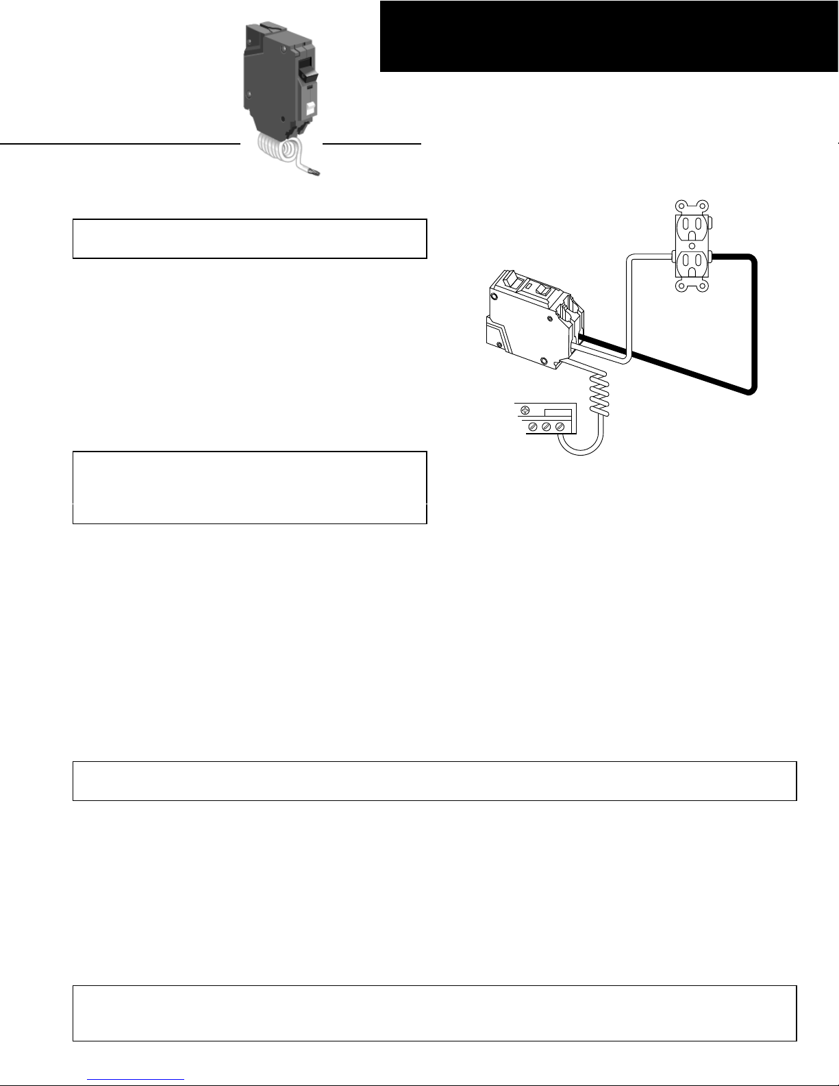
1. See installation instructions on reverse side.
2. Remove circuit breaker from “shared neutral”
circuit. Wire the circuit with dedicated two
wires plus ground. If shared neutral circuit is
required, consider utilizing GE two-pole arc-
fault circuit breaker.
3. Assess the current on the circuit drawn by all
the loads by summing all branch amperages
divide the rated wattage of each load by 120).
If this total is greater than the circuit breaker
rating, the circuit is overloaded and some of
the load should be removed.
4. Test for arc-fault by completing instructions
below.
To test for arc-fault:
Unplug all items from the receptacles in branch circuit. Reset circuit breaker by pushing its handle to the OFF
position and then to the ON position:
1. If breaker trips with all loads OFF: Check permanent electrical circuit wiring, arcing, poor insulation,
shorted wires, wet connections, wet conduit, a neutral lead pinched to a grounded metal box, receptacle
leakage, or other faults that could cause safety features in the breaker to open the circuit.
2. Switch ON one of the original loads. Reset the breaker. If breaker does not trip with this load ON, switch
on an additional load. Repeat until breaker trips. Examine last additional load for possible faults.
Loads and/or wiring suspected of having faults should not be restored to service.
INSTALLING ELECTRICIAN’S INFORMATION
Installing electrician should add the following information:
Installer’s Name
Installer’s Address
Installer’s Phone #
NN
NNOO
OOTT
TTII
IICC
CCEE
EE:::: TT
TThh
hhee
eess
ssee
ee ii
iinn
nnss
sstt
ttrr
rruu
uucc
cctt
ttii
iioo
oonn
nnss
ss dd
ddoo
oo nn
nnoo
oott
tt cc
ccoo
oovv
vvee
eerr
rr aa
aallllllll dd
ddee
eett
ttaa
aaii
iillllss
ss oo
oorr
rr
vv
vvaa
aarr
rrii
iiaa
aatt
ttii
iioo
oonn
nnss
ss ii
iinn
nn ee
eeqq
qquu
uuii
iipp
ppmm
mmee
eenn
nntt
tt nn
nnoo
oorr
rr dd
ddoo
oo tt
tthh
hhee
eeyy
yy pp
pprr
rroo
oovv
vvii
iidd
ddee
ee ff
ffoo
oorr
rr ee
eevv
vvee
eerr
rryy
yy
pp
ppoo
ooss
ssss
ssii
iibb
bbllllee
ee cc
ccoo
oonn
nntt
ttii
iinn
nngg
ggee
eenn
nncc
ccyy
yy tt
tthh
hhaa
aatt
tt mm
mmaa
aayy
yy bb
bbee
ee mm
mmee
eett
tt ii
iinn
nn cc
ccoo
oonn
nnnn
nnee
eecc
cctt
ttii
iioo
oonn
nn
ww
wwii
iitt
tthh
hh ii
iinn
nnss
sstt
ttaa
aallllllllaa
aatt
ttii
iioo
oonn
nn,,,, oo
oopp
ppee
eerr
rraa
aatt
ttii
iioo
oonn
nn,,,, oo
oorr
rr mm
mmaa
aaii
iinn
nntt
ttee
eenn
nnaa
aann
nncc
ccee
ee.... SS
SShh
hhoo
oouu
uulllldd
dd
ff
ffuu
uurr
rrtt
tthh
hhee
eerr
rr ii
iinn
nnff
ffoo
oorr
rrmm
mmaa
aatt
ttii
iioo
oonn
nn bb
bbee
ee dd
ddee
eess
ssii
iirr
rree
eedd
dd oo
oorr
rr ss
sshh
hhoo
oouu
uulllldd
dd pp
ppaa
aarr
rrtt
ttii
iicc
ccuu
uullllaa
aarr
rr
pp
pprr
rroo
oobb
bbllllee
eemm
mmss
ss aa
aarr
rrii
iiss
ssee
ee tt
tthh
hhaa
aatt
tt aa
aarr
rree
ee nn
nnoo
oott
tt cc
ccoo
oovv
vvee
eerr
rree
eedd
dd ss
ssuu
uuff
ffff
ffii
iicc
ccii
iiee
eenn
nntt
ttllllyy
yy ff
ffoo
oorr
rr tt
tthh
hhee
ee
pp
ppuu
uurr
rrcc
cchh
hhaa
aass
ssee
eerr
rr’’
’’ss
ss pp
ppuu
uurr
rrpp
ppoo
ooss
ssee
eess
ss,,,, tt
tthh
hhee
ee mm
mmaa
aatt
tttt
ttee
eerr
rr ss
sshh
hhoo
oouu
uulllldd
dd bb
bbee
ee rr
rree
eeff
ffee
eerr
rrrr
rree
eedd
dd tt
ttoo
oo
tt
tthh
hhee
ee GG
GGEE
EE CC
CCoo
oomm
mmpp
ppaa
aann
nnyy
yy....
g
GE Industrial Systems
General Electric Company
41 Woodford Ave., Plainville, CT 06062
DE -40117 R4 1001 © 2001 General Electric Company
Table of contents
Other GE Other manuals