DETECTOR DORS 1200 9
DETECTOR DORS 1200
8
ce into standby mode. At this mo
ment all illumination sources and
TV monitor are turned off, power
is cut off from external devices
connected to V1 and V2 jacks and
power consumption of the device
becomes minimal. External devices
connected to M1 and M2 jacks are
not cut off and should be switched
off separately.
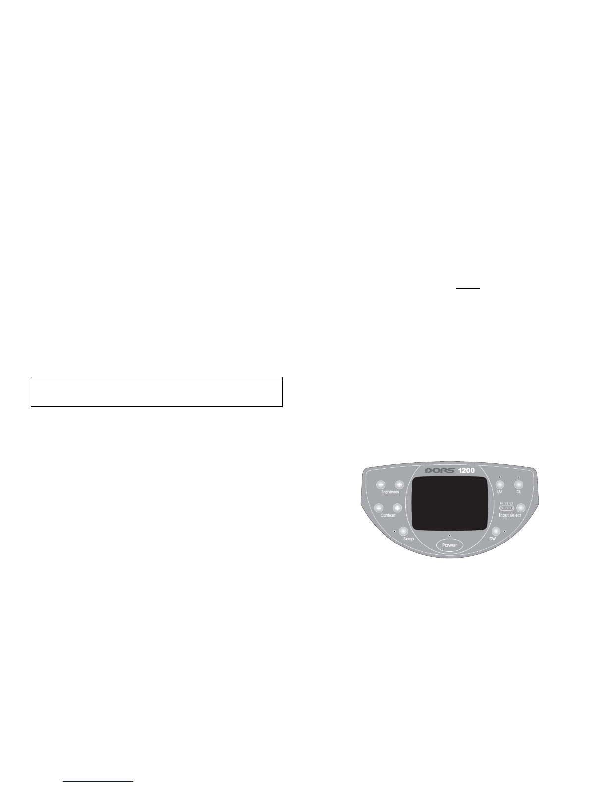
2. Sleep button (auto power off).
Setting the time for changing over
to standby mode. It is possible to
set 4 modes of operation: auto
power off not activated, auto
power off after 10 minutes, auto
power off after 30 minutes, auto
power off after 60 minutes. Chan
ge over to the next mode is perfor
med cyclically with every pressing
of the Sleep button. Red color in
dicator shows the current opera
tion mode. If auto power off is not
activated the indicator is not glow
ing. In other case during the pro
cess of setting the auto power off
time in 10/30/60 minutes the indi
cator glows in the following sequ
ence: 1 blink/pause 2 blinks/
pause 3 blinks/pause and after
several seconds it starts glowing
continuously.
3. Contrast buttons +/ (contrast
adjustment). Steppingup and
correspondingly steppingdown
contrast of the image on the moni
tor. The corresponding button
should be pressed and kept pressed
until the required contrast of the
image is achieved. At this moment
Power indicator is blinking that
confirms the adjustment process.
In case of shortterm pressing of
the + or button stepbystep fine
contrast adjustment is performed.
4. Brightness buttons +/ (bright
ness adjustment). Steppingup
and correspondingly stepping
down brightness of the image on
the monitor. The corresponding
button should be pressed and kept
pressed until the required bright
ness of the image is achieved. At
this moment Power indicator is
blinking that confirms the adjust
ment process. In case of short
term pressing of the + or button
stepbystep fine brightness ad
justment is performed.
5. DW button (double wavelength/
"M"mark). After pressing this
button the device is changed over
to mode when IR illumination pe
riodically after every 0.4 seconds
changes from 940 nm to 850 nm
and back. If the object to be verifi
ed possesses so called "M" marks
this will cause their clearly notice
able twinkling. At this moment red
color indicator near the DW button
starts to glow.
Remark: If the device was in the
mode of verifying UV marks or
banknote in transmitted white
light, the luminescent lamps are
turned off, because it is impossible
to perform this type of protection
verification with these lamps in
background. This type of verifica
tion also is not possible if direct
sunlight or light of powerful incan
descent lamps falls on the bankno
te inside the device. Repeated pres
sing of the DW button switches
off the mode and the DW indicator
goes down.
6. UV button (ultraviolet lamp). By
pressing this button UV lamps in
the upper part of the device are
tuned on thus providing possibility
to verify UV marks on objects pla
ced inside the device and simultan
eously observe IR marks (if there
are such) on the monitor of the de
vice. At this moment blue color in
dicator near the UV button starts
to glow. If the indicator is blinking
it means failure of UV lamps or in
correct operation of the device. Re
peated pressing of the UV button
switches off the UV lamp and indi
cator goes down.
Remark: If the UV is pressed the DW
mode and the mode of white lower
or white upper illumination (if they
were turned on) are turned off.
7. DL button (daylight lamps). This
button controls switching on of the
upper and lower white illumina
tion. The first pressing of the DL
button turns on the upper white il
lumination. The next pressing turns
on the lower lamp of diffused whi
te light. At this moment blue color
indicator near the DL button turns
on. If the indicator is blinking it me
ans failure of the lamp or incorrect
operation of the device. And, fina
lly, the next pressing of the button
turns off both the sources of white
light.
Remark: pressing of the DL button
switches off UV illumination mode
(if it was switched on). Turning on
of the lower white lamp switches
off the DW mode (if it was
switched on).
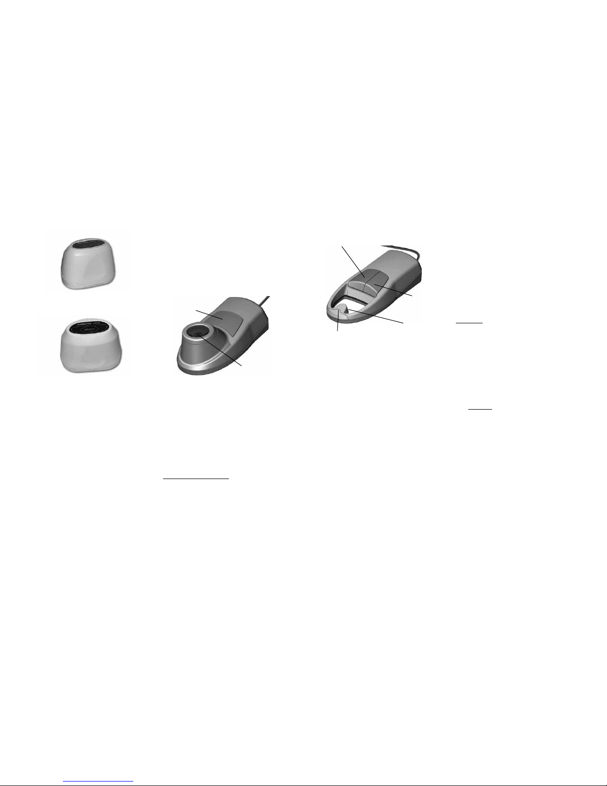
8. Input select button (selection of
the video signal source). The de
sign of the device foresees three
sources of video signal: internal
blackandwhite camera with Int IR
filter and two generalpurpose vi
deo inputs V1 and V2. By pressing
the Input select button the sour
ces are altered cyclically in the fol
lowing sequence: Int/V1/V2. In
case when the DORS 1010/1020
television magnifier is connected to
V1/V2 input turning on of the
required source can be (and re
commended to be) done by pres
sing the control button directly on
the lens. Further pressings of the
button will cyclically alter sources
of illumination in the lens. For
DORS 1010 the sequence is the fol
lowing: white/IR, and for DORS
1020 white/IR/UV. Selection of