2
IMPORTANT SAFETY INSTRUCTIONS
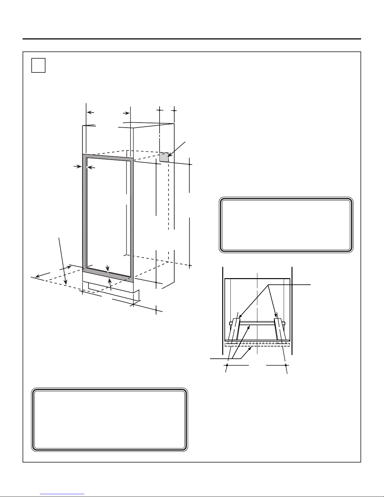
Installation Instructions
For Your Safety
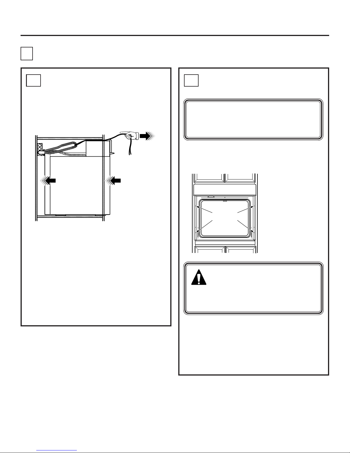
• Be sure your oven is installed properly by
a qualified installer or service technician.
• Be sure the oven is securely installed in a
cabinet that is firmly attached to the house
structure. Weight on the oven door could
cause the oven to tip and result in injury.
Never allow anyone to climb, sit, stand or
hang on the oven door.
• Make sure the cabinets and wall
coverings around the oven can withstand
the temperatures (up to 200°F [93.3°C])
generated by the oven.
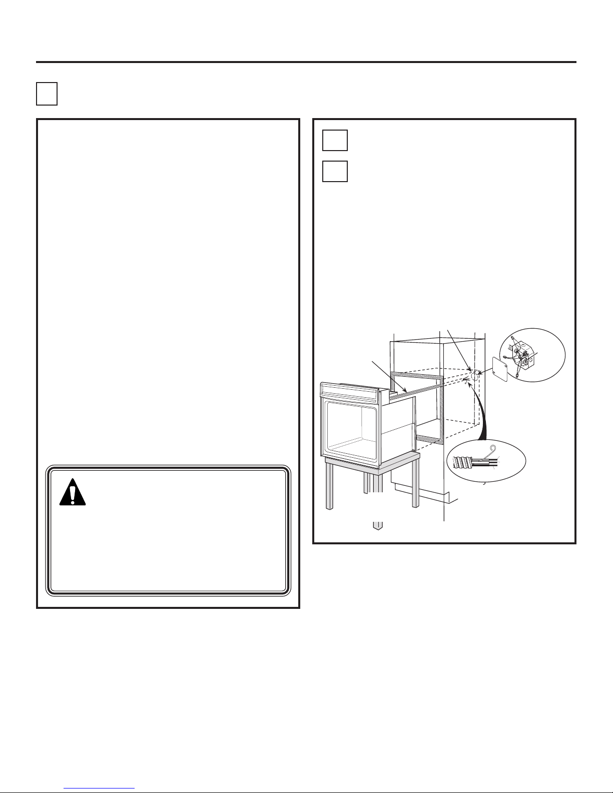
Electrical
Requirements cont.
Rating plate is located on oven side trim,
side front frame or lower front frame.
We recommend you have the electrical wiring
and hookup of your oven connected by a qualified
electrician. After installation, have the electrician
show you where your main oven disconnect is
located.
Check with your local utilities for electrical codes
which apply in your area. Failure to wire your oven
according to governing codes could result in a
hazardous condition. If there are no local codes,
your oven must be wired and fused to meet the
requirements of the National Electrical Code,
ANSI/NFPA No. 70–Latest Edition. You can
get a copy by writing:
National Fire Protection Association
Batterymarch Park
Quincy, MA 02269
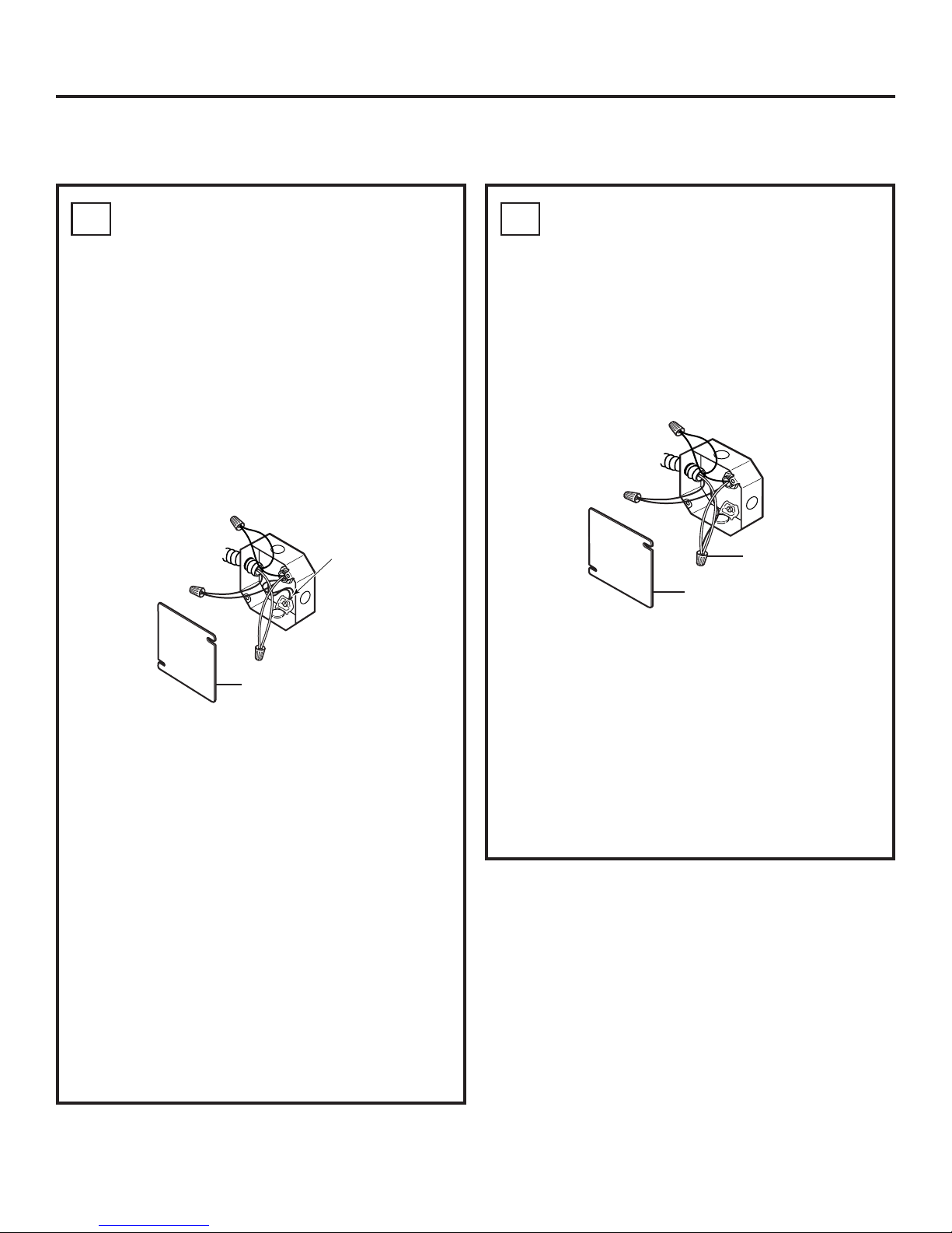
Effective January 1, 1996, the National
Electrical Code requires that new, but not existing,
construction utilize a four-conductor connection to
an electric oven. When installing an electric oven
in new construction, a mobile home, recreational
vehicle or an area where local codes prohibit
grounding through the neutral conductor,
follow the instructions in the section on NEW
CONSTRUCTION AND FOUR-CONDUCTOR
BRANCH CIRCUIT CONNECTION.
You must use a three-wire, single-phase A.C.
208Y/120 Volt or 240/120 Volt, 60 hertz electrical
system. If you connect to aluminum wiring,
properly installed connectors approved for
use with aluminum wiring must be used.
WARNING:
The electrical
power to the oven supply line
must be shut off while line
connections are being made. Failure
to do so could result in serious injury
or death.
Rating Plate
Location
Electrical
Requirements
This appliance must be supplied with the proper
voltage and frequency, and connected to an
individual, properly grounded branch circuit,
protected by a circuit breaker or fuse. See the
rating plate located on the oven frame to determine
the rating of the product. Use the chart below to
determine the minimum recommended dedicated
circuit protection.
Recommended
KW Rating KW Rating Circuit Size
240V 208V (Dedicated)
≤4.8 KW ≤4.1 KW 20 Amp
4.9 KW–7.2 KW 4.3 KW–6.2 KW 30 Amp
7.3 KW–9.6 KW 6.3 KW–8.3 KW 40 Amp
9.7 KW–12.0 KW 8.4 KW–10.4 KW 50 Amp