manuals.online logo
Brands
  1. Home
  2. •
  3. Brands
  4. •
  5. GE
  6. •
  7. Oven
  8. •
  9. GE JGB650 User manual

GE JGB650 User manual

IMPORTANT SAFETY NOTICE
THIS INFORMATION IS INTENDED FOR USE BY PERSONS POSSESSING
ADEQUATE BACKGROUNDS OF ELECTRICAL, ELECTRONIC AND MECHANICAL
EXPERIENCE. ANY ATTEMPT TO REPAIR A MAJOR APPLIANCE MAY RESULT IN
PERSONAL INJURY AND PROPERTY DAMAGE. THE MANUFACTURER OR SELLER
CANNOT BE RESPONSIBLE FOR THE INTERPRETATION OF THIS INFORMATION,
NOR CAN IT ASSUME ANY LIABILITY IN CONNECTION WITH ITS USE.
DISCONNECT POWER BEFORE SERVICING
IMPORTANT - RECONNECT ALL
GROUNDING DEVICES.
ALL PARTS OF THIS APPLIANCE CAPABLE OF CONDUCTING ELECTRICAL
CURRENT ARE GROUNDED. IF GROUNDING WIRES, SCREWS, STRAPS, NUTS
OR WASHERS USED TO COMPLETE A PATH TO GROUND ARE REMOVED FOR
SERVICE, THEY MUST BE RETURNED TO THEIR ORIGINAL POSITION AND
PROPERLY FASTENED.
CONVERSION TO LP (PROPANE) GAS
SPILL-PROOF SEALED BURNER
Brackets are mounted to the under side of the cooktop by T-15
Torx screws.
The screw heads are located under burner head (these screws
must be removed before lifting the cooktop). Screws and bracket
ensure proper alignment for gas to be injected into the burner
head. It is critical that brackets are aligned correctly and screws
fully torqued down during nal assembly.
REPLACING ORIFICE HOLDER AND TUBING
The Orice Holder and Supply Tubing are one assembly.
To replace the assembly:
• Follow the instructions under To Remove the Cooktop.
• Remove the 5/8” nut securing the orice holder being replaced
to the bracket. Use a 5/8” open ended or adjustable wrench to
loosen the nut.
• Loosen the 1/2” nut securing the tubing to the valve.
TO REMOVE COOKTOP
• Remove grates, burner caps, and heads.
• Remove T-15 torxs screws - 3 under each burner head.
• Disconnect electrode leads.
• Disengage 2 front clips using a at blade screw driver located between cooktop
and manifold approximately 2-1/2” from each side.
• Lift top up at front.
• Shift top left or right to disengage hinge pins at the rear.
IMPORTANT: Before lowering the top onto the front clips, line up the burner bracket
with the cooktop to replace screws.
NOTE: When reinstalling top, position top to be the equivalent of 1/2 way lowered
before attempting to insert the top hinge pins into the corresponding slots on the
backguard.
SPARK MODULE LOCATION
The spark module is located inside the backguard. The module is mounted by two
tabs which snap into correspoinding slots.
To remove the module from its mounting, use a small, at bladed screwdriver to
bend the mounting tab toward the module body, freeing the tabs from their slots.
SCHEMATIC DIAGRAM
WARNING Power must be disconnected before servicing this appliance.
222D8442P002
WARNING
To prevent leakage,
make sure the
orices are securely
screwed into the gas
supply tubes.
95
III
Denotes0.95mmOrifice sizeo
pening
DenotesLP (Propane) Ga s
LR RR
LF RF
LP
Blue/Brown
Orange/Lt. Blue
LP
Green/Red
LP
Red/Yellow
LP
LP
Orange/Green
BURNER OUTPUT RATINGS: BTU/HR
LP (Propane) Gas 10” W.C.P.
BURNER BTU
RATE ORIFICE SIZE
(mm) COLOR MARKINGS
RF 11,000 0.039” (0.99) Green/Red 99L
LF 10,000 0.0365” (0.92) Orange/Lt. Blue 92L
RR 5,000 0.026” (0.66) Red/Yellow 66L
LR 9,500 0.035” (0.89) Blue/Brown 89L
C 8,000 0.034” (0.86) Orange/Green 86L
BAKE 16,000 0.047” (1.19) Orange .047
BROIL 12,000 0.041” (1.04) Red 041L
198
III
Denotes1.98 mm Orifice sizeopening
DenotesNatural Gas
N
BURNER OUTPUT RATINGS: BTU/HR
NG (Natural) Gas 5” W.C.P.
BURNER BTU
RATE
ORIFICE SIZE
(mm) COLOR MARKING
RF 17,000 0.0756” (1.92) Black 192N
LF 11,000 0.058” (1.48) Orange 148N
RR 5,000 0.040” (1.01) White/Purple 101N
LR 9,500 0.056” (1.41) Yellow 141N
C 8,000 0.050” (1.27) Blue 127N
BAKE 16,000 0.070” (1.78) None .070
BROIL 13,500 0.066” (1.67) Red 066N
COLORSYMBOLCOLOR
REDRROJO
WHITE
WB
LANCO
ORANGE
ON
ARANJA
GREEN
GV
ERDE
YELLOWYAMARILLO
VIOLET
VV
IOLETA
BLUE
NA
ZUL
GRAY
SG
RIS
1
AT 75 F 1091 5.3 OHMS.
AT 865 F 2634 23.5 OHMS.
OV TEMP SENSOR
W
W
Y
E2
E1
R
5
Y
N
R
R
O
OV
W
LATCH SWITCH/DOOR SWITCH
NC = UNLOCKED
GLOWBAR
ELECTRONIC
CONTROL BRD.
W
RR
D1 W
BAKE
BROIL
GLOBAR
LR
B
W
NO = LOCKED
W
W
CONTROL
VALVE
W
W
W
LEFT IGNITER
FOR ELECTRICAL RATING
SEE RATING PLATE
RR SW
RIGHT IGNITER
RF LF
LF SW
C2
LR SW
W
A2
W
N
F1
N
D2
W
120VAC
135 OHMS.
JP1 JP2
WF2
BAKE OV
BROIL
A1
L-1
RC1
V
RF SW MIDDLE
MIDDLE
B
LATCH NO SW
W
N
L
NOTES:
- - - -THIS CIRCUIT NOT IN ALL MODELS.
JGB650 SINGLE OVEN
31-17081 06-13 GE
OVEN TEMPERATURE CALIBRATION
The bake temperature can be adjusted from its factory calibration (+or -)
35˚F in 1˚ increments.
1. Press and hold both the BAKE and BROIL pads for about 2 seconds
until the display shows SF.
2. Press the BAKE pad. The current offset setting is in the display.
3. Enter the desired temperature offset using the number pads.
4. Use the BAKE pad to toggle between +/-.
5. Press START key. The display will return to Time or Day Clock.
BAKE BURNER REMOVAL
• Remove oven door and drawer.
• Remove the screws on the oven oor at the back of the oven cavity and
remove oven oor/deector.
• Remove 1/4” hex head screws from the bracket holding the burner to
the back wall of the range.
• Remove the screw at the front of the burner.
• Disconnect the igniter wires.
• Remove the Bake Burner.
BACKGUARD DISASSEMBLY
• Remove screws located on the back of the backguard. (There is a set of
screws on each side.)
• Remove the torx screw on the front inside corner of backguard (1 on
each side).
• Gently lift backguard off.
• Be sure to reassemble rear cover and backguard per original assembly.
OVEN BURNER IGNITION SYSTEM
The ignitor is a “Norton” style rectangular glowbar. The ignition circuit
consists of the electronic control, the igniter, and the oven safety valve
(gas valve). The three components are wired in series.
The most important points to know about the ignition system are:
1. THE IGNITOR RESISTANCE DECREASES AS THE IGNITER SURFACE
TEMPERATURE INCREASES.
2. THE SAFETY VALVE OPERATES BY CURRENT, NOT VOLTAGE.
From a cold start, the ignitor needs 30-60 seconds, with voltage applied, to
reduce the electrical resisteance enough to provide a minimum of 2.9 amps
of current ow in the series circuit. This is the required current ow needed
for the safety valve to open to supply gas to the burner. The glowbar should
provide a steady current ow of between 3.2 to 3.6 amps owing in the circuit.
The igniter will remain energized at all times during burner operation. If the
igniter glows red but does not draw at least 2.9 amps, the fault is usually with
the igniter, not the valve. Always check the oven shut-off valve for a “No Oven”
condition.
CONTROL SYSTEMS
There are three versions of the control used on gas ranges. Versions 1, 2 and
3. Features and appearance will vary by model:
Version 1
Has Delay Start and Cook Time features.
Version 2
Has Delay Start, Cook Time and Self Clean features.
Version 3
Has Delay Start, Cook Time, Self Clean and Convection Bake features.
GLOWBAR IGNITION CIRCUIT
L1 N
120 V
T´STAT
T1 to 1.2 Ohms
GLOW BAR
IGNITER OVEN
VALVE
IGNITER GLOWBAR REPLACEMENT
The igniter glowbar and its protective cage are one assembly on
this Norton style igniter. The round Carborundum igniter CANNOT be
substituted for the rectangular Norton Igniter.
• Remove the burner from
the oven. See Bake Burner
Removal in this manual.
• Remove the 1/4” hex head
screws securing the igniter
to the burner.
• Remove the old igniter.
• Install the new igniter and
re-install the two 1/4” hex
head screws to secure the
igniter.
• Reinstall the burner.
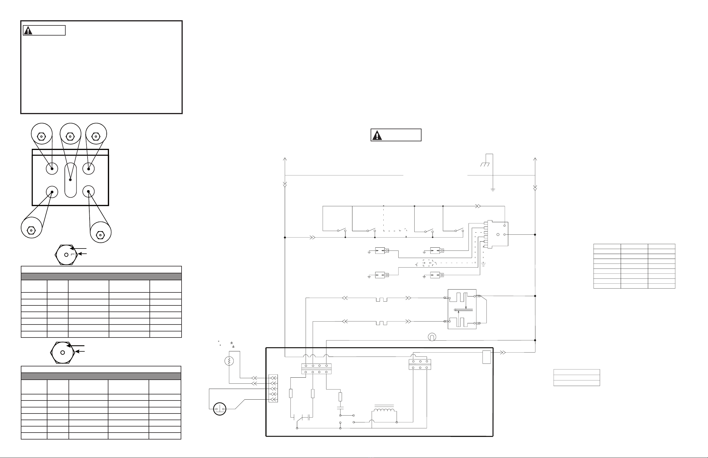
WIRING DIAGRAM
WARNING Power must be
disconnected before servicing this
appliance.
222D8441P002
FAILURE MEANING CORRECTION
CODE
SHORTED
CANCEL/OFF KEY
Power down then power up the range. If the fault
condition reappears within 15 minutes–REPLACE
CONTROL.
OVEN
OVERTEMPERATURE
CONDITION
• Door unlocked–oven
exceeded ~620°F
• Door locked–oven
exceeded ~930°F
• Door latch unlocked
while oven in excess
of ~620°F
1. If no overtemperature condition occurred–check all
contacts and connections in sensor circuit. Eliminate
excessive resistance in sensor circuit due to increased
contact/connector resistance.
2. If overtemperature condition occurred–look for
welded relay contacts on bake, broil, or double-line-
break relays. If relay contact welding is confirmed–
REPLACE CONTROL.
3. Ensure Door Latch stays locked for duration of CLEAN
cycle.
F2
OPEN OVEN SENSOR
Sensor resistance
>2900 ohms
Disconnect sensor/latch connector from the control.
Measure sensor circuit resistance at sensor/lock switch
connector (should be ~1100 ohms at room temperature).
Ensure each sensor lead to chassis ground resistance is
infinitely high.
If open or short circuit is detected:
1. Look for cut or pinched sensor harness wire.
2. Look for sensor leads shorted to chassis ground.
3. Look for loss of terminal contact in the harness and at
the control.
4. Check sensor resistance directly at sensor harness
connector (away from the control). If reading is
abnormal–REPLACE OVEN SENSOR.
If sensor circuit appears to be normal:
1. Reinstall sensor/lock switch connector on the control
and measure sensor resistance at solder joints on
the back of the control circuit board. If abnormal
resistance reading is observed–RESTORE CONTACT
PRESSURE OR SENSOR/LOCK SWITCH CONNECTOR.
If corrective actions above do not eliminate the
problem–REPLACE CONTROL.
F3
SHORTED OVEN
SENSOR
Sensor resistance
<950 ohms
F4
SHORTED MATRIX
KEY
Power down then power up the range. If the fault
condition reappears within 15 minutes–REPLACE
CONTROL.
F7
EEPROM ERROR Power down then power up the range. If the fault
condition reappears within 5 minutes–REPLACE
CONTROL.
F8
CONTROL
SUPERVISORY
CIRCUIT FAILURE
REPLACE CONTROL.
F5
F0
T09 FAULT CODES
OVEN SENSOR
1100 OHMS@ROOM TEMP
2650 OHMS@CLEAN TEMP
OVEN SENSOR
PINS 4 & 5
DOOR LOCK CIR.
PINS 1 & 3
DOOR LOCK CIR.
PINS 1 & 3
PIN 2 BLANK
CNC
LCH. SW.
LATCH
BI-METAL
(THERMAL
LOCK)
LOCK
SWITCH
UNLOCK
LOCK
LOCK
COLOR SYMBOL
LAST
NUMBER USED
RED R3
WHITE W10
ORANGE O2
YELLOW Y2
VIOLET V2
BLUEN 2
GRAY S-
BROWNC -
BLACK B-
BLACK/WHITE B/W -
200 C
200 C
R
ELECTRONIC CONTROL
COM
150 C
150 C
MD
SW
V
150 C
V
V
150°C W-7
VALVE
CONTROL
IGNITOR
BAKE
R150 C
RF
SW
150 C
V
V
BROIL
IGNITOR
R
SENSOR
OVEN
150 C
1
2
D
LF
SW
NC
LR
150 C
LR
SW
V
V
ELECTRODE
MD
Y-2 250 C
200 C
IGNITION
MODULE
ELECTRODE
LCH SW
LF
O-2
1
250 C
1
W-9
5
W-8
5
150 C
150 C
N-2
W-6
Y-1
2
1
E
W-8
W-9
200 C
200 C
150 C R
R-3
V-2
C1
N-1
150 C W-2 125 C
150° C N-2
W-5
O-1
LIGHT
OVEN
150 C
150 C
W-3 125 C
V-1
R-2 125° C
125 C
2
R-2
W-4 125°C
125 C
B/W
N
A
2
L1
1B
G
Y-1 150°C
R-1 125°C
W-1 125°C
N-1 150°C
W-1
125 C
NO
F
B
W-10
0-1 150°C
125 C
R-1
150 C
GND
105 C
GND
G
L
BR
BA N
OL
W-1
W-2
W-6
W-5
150 C
RR
SW
V
RR 200 C
ELECTRODE
RF 200 C
NOTES:
ALL LEADS WITH DESIGNATION
NUMBERS THAT ENTER COMMON
LEAD PATH( ) MUST BE
TRACED TO THEIR TERMINATIONS.
- - - -THIS CIRCUIT NOT IN ALL MODELS.
W-3 125°C
V-1
N
L
125°C

Other GE Oven manuals

GE JGRS14 User manual

GE

GE JGRS14 User manual

GE PCT920 User manual

GE

GE PCT920 User manual

GE Profile advantium SCB1000 User manual

GE

GE Profile advantium SCB1000 User manual

GE JK1000DFBB Manual

GE

GE JK1000DFBB Manual

GE JB850 User manual

GE

GE JB850 User manual

GE JKP50SHSS Manual

GE

GE JKP50SHSS Manual

GE JKC06GJ Specification sheet

GE

GE JKC06GJ Specification sheet

GE PT925SNSS - Profile 30" SC Convection Ovens User manual

GE

GE PT925SNSS - Profile 30" SC Convection Ovens User manual

GE JT965 User manual

GE

GE JT965 User manual

GE PK7000DF2WW User manual

GE

GE PK7000DF2WW User manual

GE Monogram ZET757WD1WW User manual

GE

GE Monogram ZET757WD1WW User manual

GE JGRS06BEJ User manual

GE

GE JGRS06BEJ User manual

GE Monogram ZET857WBWW User guide

GE

GE Monogram ZET857WBWW User guide

GE Profile JB968SLSS User instructions

GE

GE Profile JB968SLSS User instructions

GE JK1000 Manual

GE

GE JK1000 Manual

GE Profile JT980SHSS User manual

GE

GE Profile JT980SHSS User manual

GE HGP6070E User manual

GE

GE HGP6070E User manual

GE PT7550 User manual

GE

GE PT7550 User manual

GE Cafe CKS70DP2NS1 User manual

GE

GE Cafe CKS70DP2NS1 User manual

GE Profile Advantium SCA2000BAA User manual

GE

GE Profile Advantium SCA2000BAA User manual

GE 840081100 User manual

GE

GE 840081100 User manual

GE MONOGRAM ZEK755 User manual

GE

GE MONOGRAM ZEK755 User manual

GE PTD7000 User manual

GE

GE PTD7000 User manual

GE Profile Advantium PSB1001NSS User guide

GE

GE Profile Advantium PSB1001NSS User guide

Popular Oven manuals by other brands

Maytag MEW9630AB Use and care guide

Maytag

Maytag MEW9630AB Use and care guide

EF BO-AE 5640 SS-TN Installation & user's instructions

EF

EF BO-AE 5640 SS-TN Installation & user's instructions

Brandt BOP7568LX User instructions

Brandt

Brandt BOP7568LX User instructions

Siemens HB13AB 50B Series instruction manual

Siemens

Siemens HB13AB 50B Series instruction manual

EAS Electric EMV75TVP user manual

EAS Electric

EAS Electric EMV75TVP user manual

Smeg SO6606WAPNR manual

Smeg

Smeg SO6606WAPNR manual

AEG Electrolux COMPETENCE D1100-4 Installation and operating instructions

AEG Electrolux

AEG Electrolux COMPETENCE D1100-4 Installation and operating instructions

Siemens HB36D.72 instruction manual

Siemens

Siemens HB36D.72 instruction manual

Siemens CS658GR 6B Series instruction manual

Siemens

Siemens CS658GR 6B Series instruction manual

GILMAN gemeni GSO17G manual

GILMAN

GILMAN gemeni GSO17G manual

Indesit IS50ES operating instructions

Indesit

Indesit IS50ES operating instructions

AEG BPS356020M user manual

AEG

AEG BPS356020M user manual

eka MKF 464 S TRANSLATION OF ORIGINAL INSTALLATION AND MAINTENANCE MANUAL

eka

eka MKF 464 S TRANSLATION OF ORIGINAL INSTALLATION AND MAINTENANCE MANUAL

Electrolux EOG 900 product manual

Electrolux

Electrolux EOG 900 product manual

CDA SV430 Manual for installation, use and maintenance

CDA

CDA SV430 Manual for installation, use and maintenance

SCHOLTES FNG 66 S operating instructions

SCHOLTES

SCHOLTES FNG 66 S operating instructions

Bosch HBX33R51 Instruction manua

Bosch

Bosch HBX33R51 Instruction manua

Maytag MEW6627DDW - Electric 27 in. Double Wall... Repair parts list

Maytag

Maytag MEW6627DDW - Electric 27 in. Double Wall... Repair parts list

manuals.online logo
manuals.online logoBrands
  • About & Mission
  • Contact us
  • Privacy Policy
  • Terms and Conditions

Copyright 2025 Manuals.Online. All Rights Reserved.