GE JGBP85 User manual

Installation Instructions
WARNING!
INSTALLATION SAFETY
INSTRUCTIONS
Read these instructions completely and carefully.
Improper installation, adjustment, alteration, service
or maintenance can cause injury or property
damage. Refer to this manual. For assistance or
additional information, consult a qualified installer,
service agency, manufacturer (dealer) or the gas
supplier.
Never reuse old flexible connectors. The use
of old flexible connectors can cause gas leaks and
personal injury. Always use NEW flexible connectors
when installing a gas appliance.
IMPORTANT – Remove all packing material
and literature from oven before connecting gas and
electrical supply to range.
CAUTION – Do not attempt to operate the
oven of this range during a power failure (Electric
Ignition models only).
■Have your range installed by a qualified installer.
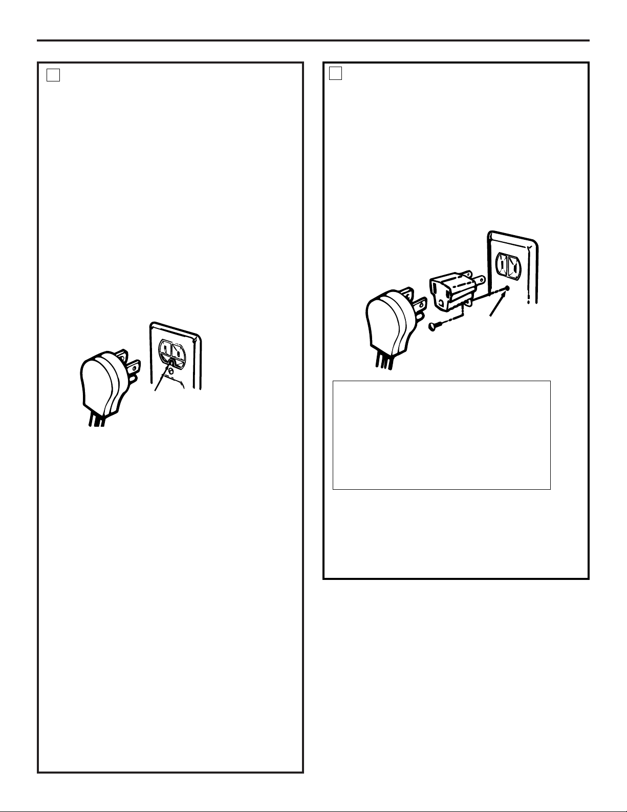
■Your range must be electrically grounded in
accordance with local codes or, in the absence
of local codes, in accordance with the National
Electrical Code (ANSI/NFPA 70, latest edition).
In Canada, electrical grounding must be in
accordance with the current CSA C22.1 Canadian
Electrical Code Part 1 and/or local codes. See
Electrical Connections in this section.
■efore installing your range on linoleum or any other
synthetic floor covering, make sure the floor covering
can withstand 180°F without shrinking, warping or
discoloring. Do not install the range over carpeting
unless a sheet of 1/4″thick plywood or similar
insulator is placed between the range and carpeting.
■Make sure the wall coverings around the range can
withstand heat generated by the range up to 200°F.
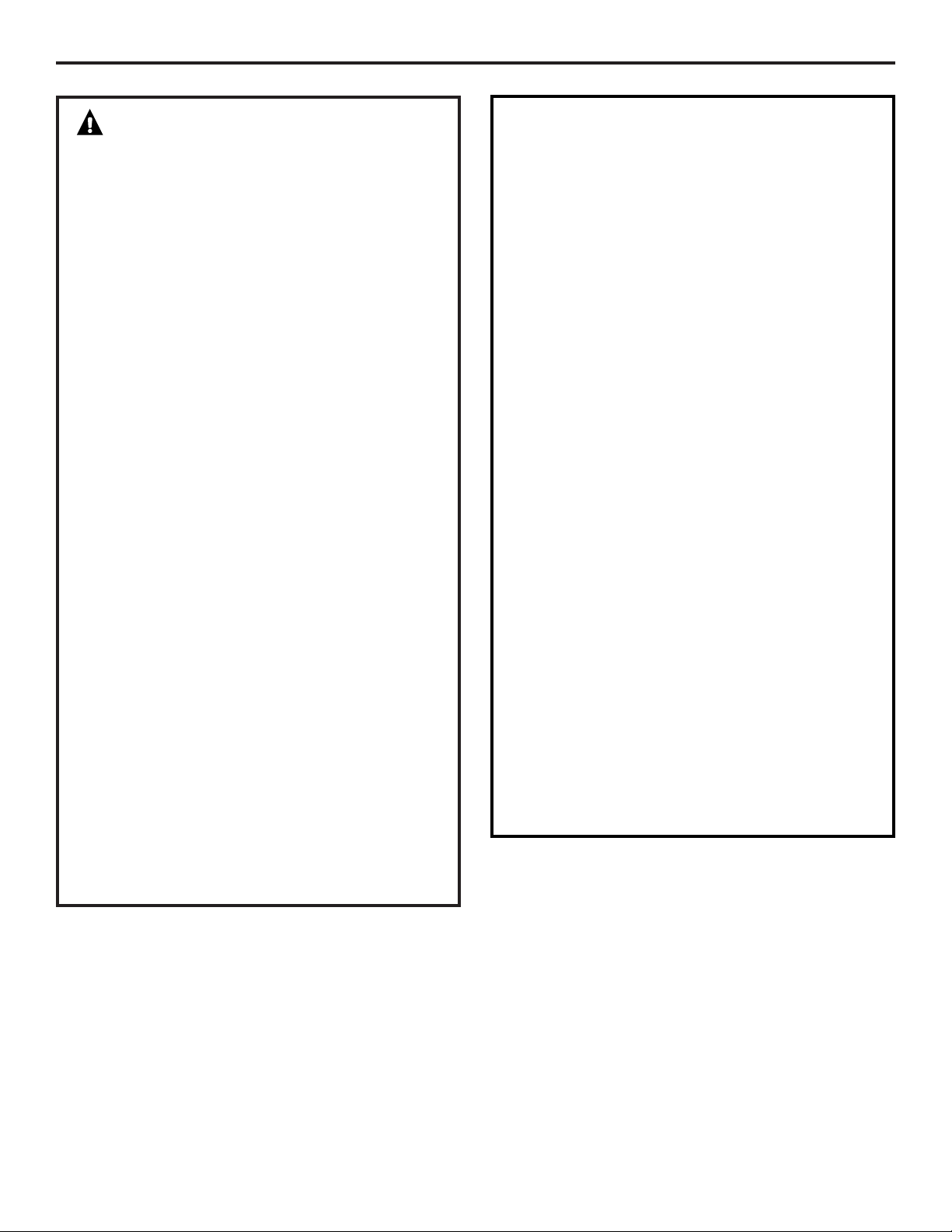
■Avoid placing cabinets above the range. To reduce
the hazard caused by reaching over the open flames
of operating burners, install a ventilation hood over
the range that projects forward at least 5″beyond
the front of the cabinets.
■The ventilating hood must be constructed
of sheet metal not less than 0.0122″thick.
Install above the cooktop with a clearance of not less
than 1/4″between the hood and the underside of the
combustible material or metal cabinet. The hood
must be at least as wide as the appliance and
centered over the appliance. Clearance between the
cooking surface and the ventilation hood surface
MUST NEVER BE LESS THAN 24 INCHES.
EXCEPTION: Installation of a listed microwave oven or
cooking appliance over the cooktop shall conform to
the installation instructions packed with that appliance.
■If cabinets are placed above the range,
allow a minimum clearance of 30″between the
cooking surface and the bottom of unprotected
cabinets.
■If a 30″clearance between cooking surface and
overhead combustible material or metal cabinets
cannot be maintained, protect the underside of the
cabinets above the cooktop with not less than 1/4″
insulating millboard covered with sheet metal not less
than 0.0122″thick. Clearance between the cooking
surface and protected cabinets MUST NEVER BE LESS
THAN 24 INCHES.
■The vertical distance from the plane of the cooking
surface to the bottom of adjacent overhead cabinets
extending closer than 1″to the plane of the range
sides must not be less than 18″. (See the Dimensions
and Clearances illustration in this section.)
■CAUTION – Items of interest to children
should not be stored in cabinets above a range or on
the backsplash of a range—children climbing on the
range to reach items could be seriously injured.
43

293/4”
Depth with door closed (includes door handle)
Depth varies depending on model.
See specifications sheet for your model.
30”
361/4” ± 1/4”
To cabinets below
cooktop and at
the range back
30”
30”
6”
Minimum
13”
Minimum
clearance to
right wall
Maximum depth
for cabinets
above
countertops
Front edge of
the range side
panel forward
from cabinet
18”
0”
1/4”
Minimum to
cabinets on
either side
of the range
36”
473/4”
Depth with door open:
46 3/4”
Height
Installation Instructions
Provide adequate clearances between the range and adjacent combustible surfaces. These dimensions must be
met for safe use of your range. The location of the electrical outlet and pipe opening (see Gas Pipe and Electric
Outlet Locations) may be adjusted to meet specific requirements.
The range may be placed with 0″clearance (flush) at the back wall.
DIMENSIONS AND CLEARANCES
44
3”
Minimum
clearance
to left wall

45
Installation Instructions
WARNING!
ANTI-TIP DEVICE
All ranges can tip and injury could
result.
To prevent accidental tipping of the range,
attach an approved Anti-Tip device to the
wall. (See Installing the Anti-Tip Device in
this section.) To check if the device is
installed and engaged properly, carefully
tip the range forward. The Anti-Tip device
should engage and prevent the range from
tipping over.
If you pull the range out from the wall for
any reason, make sure the Anti-Tip device
is engaged when you push the range back
against the wall.
■For your safety, never use your range for warming
or heating the room. Your oven and cooktop are not
designed to heat your kitchen. Top burners should
not be operated without cookware on the grate. Such
abuse could result in fire and damage to your range
and will void your warranty.
■Do not store or use combustible materials,
gasoline or other flammable vapors and liquids
in the vicinity of this or any other appliance.
Explosions or fires could result.
■Do not use oven for a storage area. Items stored
in the oven can ignite.
■Do not let cooking grease or other flammable
materials accumulate in or near the range.
LOCATION
Do not locate the range where it may be subject to
strong drafts. Any openings in the floor or wall behind
the range should be sealed. Make sure the openings
around the base of the range that supply fresh air
for combustion and ventilation are not obstructed
by carpeting or woodwork.
Your range, like many other household items, is
heavy and can settle into soft floor coverings such as
cushioned vinyl or carpeting. Use care when moving
the range on this type of flooring. It is recommended
that the following simple and inexpensive instructions
be followed to protect your floor.
The range should be installed on a sheet of plywood
(or similar material). When the floor covering ends at the
front of the range, the area that the range will rest on
should be built up with plywood to the same level or
higher than the floor covering.
This will allow the range to be moved for cleaning
or servicing. Also, make sure your floor covering will
withstand 180°F. (See the Installation Safety Instructions
section.)
Make sure the wall coverings around your range can
withstand the heat generated (up to 200°F) by the
range. (See the Installation Safety Instructions section.)
IMPORTANT!
Remove all tape and packaging. Make sure the
burners are properly seated and level.
Take the accessory pack out of the oven and/or
drawer.
Check to be sure that no range parts have come loose
during shipping.

46
Installation Instructions
PROVIDE ADEQUATE GAS SUPPLY
1
Your range is designed to operate at a pressure of 5″
of water column on natural gas or, if designed for LP
gas (propane or butane), 10″of water column.
Make sure you are supplying your range with the type
of gas for which it is designed.
This range is convertible for use on natural or
propane gas. If you decide to use this range on LP gas,
conversion must be made by a qualified LP installer
before attempting to operate the range on that gas.
For proper operation, the pressure of natural gas supplied
to the regulator must be between 5″and 13″of water
column.
For LP gas, the pressure supplied must be between 10″
and 13″of water column.
When checking for proper operation of the regulator,
the inlet pressure must be at least 1″greater than the
operating (manifold) pressure as given above.
The pressure regulator located at the inlet of the range
manifold must remain in the supply line regardless of
whether natural or LP gas is being used.
A flexible metal appliance connector used to connect the
range to the gas supply line should have an I.D. of 1/2″
and be 5 feet in length for ease of installation. In Canada,
flexible connectors must be single wall metal connectors
no longer than 6 feet in length.
CONNECT THE RANGE TO GAS
2
Shut off the main gas supply valve before
disconnecting the old range and leave it off until the
new hook-up has been completed. Don’t forget to
relight the pilot on other gas appliances when you turn
the gas back on.
ecause hard piping restricts movement of the range,
the use of a CSA International-certified flexible metal
appliance connector is recommended unless local codes
require a hard-piped connection.
Never use an old connector when installing a new range.
If the hard piping method is used, you must carefully
align the pipe; the range cannot be moved after the
connection is made.
To prevent gas leaks, put pipe joint compound on, or wrap
pipe thread tape with Teflon* around, all male (external)
pipe threads.
A. Install a manual gas line shut-off valve in the gas line
in an easily accessed location outside of the range.
Make sure everyone operating the range knows where
and how to shut off the gas supply to the range.
B. Install male 1/2″flare union adapter to the 1/2″NPT
internal thread at inlet of regulator. Use a backup
wrench on the regulator fitting to avoid damage.
When installing the range from the front, remove
the 90° elbow for easier installation.
C. Install male 1/2″or 3/4″flare union adapter to the
NPT internal thread of the manual shut-off valve,
taking care to back-up the shut-off valve to keep it
from turning.
D. Connect flexible metal appliance connector to the
adapter on the range. Position range to permit
connection at the shut-off valve.
E. When all connections have been made, make sure
all range controls are in the off position and turn on the
main gas supply valve. Use a liquid leak detector at all
joints and connections to check for leaks in the system.
When using test pressures greater than 1/2 psig to
pressure test the gas supply system of the residence,
disconnect the range and individual shut-off valve from
the gas supply piping. When using test pressures of 1/2
psig or less to test the gas supply system, simply isolate
the range from the gas supply system by closing the
individual shut-off valve.
*Teflon: Registered trademark of DuPont
WARNING: DO NOT USE A FLAME TO
CHECK FOR GAS LEAKS.

Installation Instructions
47
Recommended area for 120V outlet
on rear wall and area for through-
the-wall connection of pipe stub
and shut-off valve.
Recommended area for
through-the-floor
connection of pipe stub
and shut-off valve.
9”
30”
2”
4”4”
24”
13”
141/2”
21/2”
3”
61/2”
Recommended area for 120V
outlet on rear wall and area for
through-the-wall connection
of pipe stub and shut-off valve.
Recommended area for
through-the-floor connection
of pipe stub and shut-off valve.
GAS PIPE AND ELECTRICAL UTLET L CATI NS
For models JGBP85, JGBP88, JGBP89, JGBP9 , JGBP92, PGB9 , PGB9 8 and PGB91 only.
(See the below section for models
PGB916, PGB918 and PGB975.)
GAS PIPE AND ELECTRICAL UTLET L CATI NS
For models PGB916, PGB918 and PGB975 only.
(See the above section for models JGBP85,
JGBP88, JGBP89, JGBP9 , JGBP92,
PGB9 , PGB9 8 and PGB91 .)

49
Installation Instructions
ELECTRICAL CONNECTIONS
Electrical Requirements
120-volt, 60 Hertz, properly grounded dedicated circuit
protected by a 15-amp or 20-amp circuit breaker or time
delay fuse.
E tension Cord Cautions
ecause of potential safety hazards associated
with certain conditions, we strongly recommend against
the use of an extension cord. However, if you still elect to
use an extension cord, it is absolutely necessary that it
be a UL-listed, 3-wire grounding-type appliance extension
cord and that the current carrying rating of the cord in
amperes be equivalent to, or greater than, the circuit
rating.
Grounding
IMPORTANT—(Please read carefully)
FOR PERSONAL SAFETY, THIS APPLIANCE MUST BE
PROPERLY GROUNDED.
The power cord of this appliance is equipped with a
three-prong (grounding) plug which mates with a
standard three-prong grounding wall receptacle to
minimize the possibility of electric shock hazard from
this appliance.
The customer should have the wall receptacle and
circuit checked by a qualified electrician to make sure
the receptacle is properly grounded.
Where a standard two-prong wall receptacle is
encountered, it is the personal responsibility and
obligation of the customer to have it replaced with
a properly grounded three-prong wall receptacle.
DO NOT, UNDER ANY CIRCUMSTANCES,
CUT OR REMOVE THE THIRD (GROUND) PRONG FROM
THE POWER CORD.
A word about GFCI’s – GFCI’s are not required or
recommended for gas range receptacles.
Ground Fault Circuit Interrupters (GFCI’s) are
devices that sense leakage of current in a circuit and
automatically switch off power when a threshold leakage
level is detected. These devices must be manually reset
by the consumer. The National Electrical Code requires
the use of GFCI’s in kitchen receptacles installed to serve
countertop surfaces. Performance of the range will not be
affected if operated on a GFCI-protected circuit but
occasional nuisance tripping of the GFCI breaker is
possible.
Preferred Method
Ensure proper ground
exists before use
ELECTRICAL CONNECTIONS (CONT.)
3
A. Usage Situations where Appliance Power Cord will
be Disconnected Infrequently.
An adapter may be used only on a 15-amp circuit.
Do not use an adapter on a 20-amp circuit. Where
local codes permit, a TEMPORARY CONNECTION
may be made to a properly grounded two-prong wall
receptacle by the use of a UL-listed adapter, available
at most hardware stores. The larger slot in the adapter
must be aligned with the larger slot in the wall receptacle
to provide proper polarity in the
connection of the power cord.
When disconnecting the power cord from the adapter,
always hold the adapter with one hand. If this is not done,
the adapter ground terminal is very likely to break with
repeated use. Should this happen, DO NOT USE the
appliance until a proper ground has again been
established.
CAUTION: Attaching the adapter
ground terminal to the wall receptacle cover
screw does not ground the appliance unless
the cover screw is metal, and not insulated,
and the wall receptacle is grounded through
the house wiring. The customer should have
the circuit checked by a qualified electrician to
make sure the receptacle is properly grounded.
Temporary Method
Ensure proper
ground and firm
connection before
use
(Adapter plugs not permitted in Canada)
Align large prongs/slots
3
This manual suits for next models
7
Table of contents
Other GE Range manuals

GE
GE Appliances Quickset III User manual

GE
GE Profile J2S968BH User manual

GE
GE JGB820SEPSS - 30-in Gas Range Manual

GE
GE RGB744GEH Installation instructions

GE
GE JGBS80SEMSS Manual

GE
GE JB735 User manual

GE
GE JB745 User manual

GE
GE JGB928 Original instructions

GE
GE JGAS02EN Training manual

GE
GE PGS908BEMBB User manual
Popular Range manuals by other brands

Whirlpool
Whirlpool 30" (76.2 CM) FREESTANDING GAS RANGES installation instructions

Whirlpool
Whirlpool WERP4120SS0 installation instructions

DCS
DCS RG series Part list manual

Falcon
Falcon E350/30 User instructions

Electrolux
Electrolux EW30GS75KSA Use & care guide

Whirlpool
Whirlpool RF316PXP Use & care guide