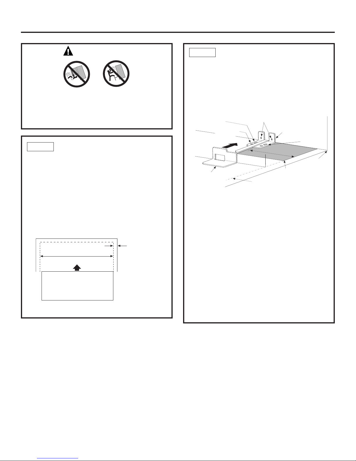
GE Drawer Freezer Refrigerator User manual

Installation
Instructions
Stainless Steel Free-Standing,
Drawer Freezer Refrigerator
monogram.com
31-46515
225D1974P005

Safety Information
wCAUTION:
Due to the weight and size of this refrigerator, and to
reduce the risk of personal injury or damage to the
product – TWO PEOPLE ARE REQUIRED FOR PROPER
INSTALLATION.
wPRUDENCE :
Àcause du poids et de la taille de ce réfrigérateur et
pour réduire le risque de blessure et de dommages,
IL FAUT DEUX PERSONNES POUR FAIRE L’INSTALLATION
CORRECTEMENT.
wWARNING:
•Use this appliance only for its intended purpose.
•Immediately repair or replace electric service cords
that become frayed or damaged.
•Unplug the refrigerator before cleaning or making
repairs.
•Repairs should be made by a qualified service
technician.
wAVERTISSEMENT :
•Il ne faut utiliser cet appareil que pour l’utilisation
appropriée.
•Réparer ou remplacer immédiatement tout cordon
électrique effiloché ou endommagé.
•Il faut débrancher le réfrigérateur avant le nettoyage
ou toute intervention.
•Les réparations doivent être faites par un technicien
qualifié.
For Monogram local service in your area,
call 1.800.444.1845.
For Monogram service in Canada,
call 1.800.561.3344
For Monogram Parts and Accessories,
call 1.800.626.2002.
www.monogram.com
2
BEFORE YOU BEGIN
Read these instructions completely and carefully.
•IMPORTANT –Save these instructions
for local inspector’s use.
•IMPORTANT –Observe all governing
codes and ordinances.
•Note to Installer –Be sure to leave these
instructions with the Consumer.
•Note to Consumer –Keep these instructions with
your Owner’s Manual for future reference.
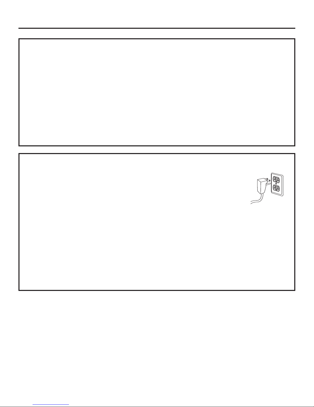
wWARNING:
This appliance must be properly grounded. See
“Grounding the Refrigerator,” page 4.
wAVERTISSEMENT :
Cet appareil doit êtrecorrectement mis à la terre.
Consulter « Mise à la terre du réfrigérateur », page 4.
If you received a damaged refrigerator, you should
immediately contact your dealer or builder.
Skill Level – Installation of this refrigerator requires
basic mechanical, carpentry and plumbing skills.
Proper installation is the responsibility of the installer.
Product failure due to improper installation is not
covered under the GE Appliance Warranty.
See the Owner’s Manual for warranty information.
CONTENTS
Planning Information
Product Dimensions and Clearances............................................3
The Installation Space..........................................................................3
Installation Instructions
Tools, Hardware, Materials ................................................................4
Grounding the Refrigerator ..............................................................4
Step 1, Measure Cabinet Opening ................................................5
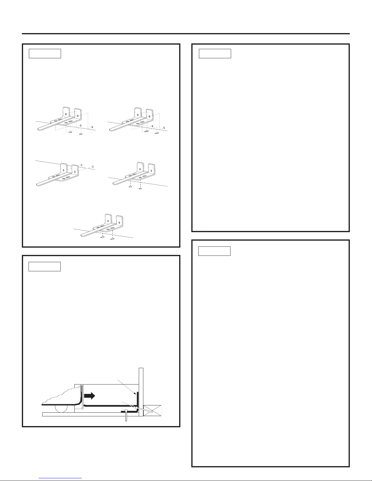
Step 2, Install Anti-Tip Bracket ....................................................5-6
Step 3, Install the Refrigerator ........................................................7
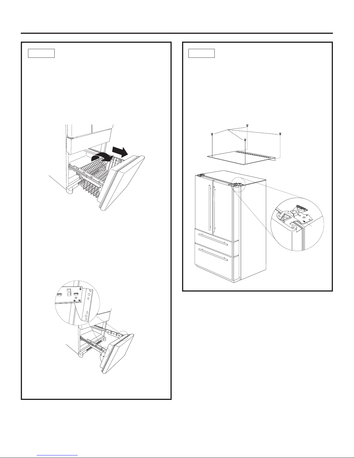
Step 4, Remove the Freezer Drawers ......................................7-8
Step 5, Removethe Fresh Food Doors ........................................8
Step 6, Remove the Toekick ..............................................................9
Step 7, Move the Refrigerator ..........................................................9
Step 8, Replace the Freezer Drawers ....................................9-10
Step 9, Replace Fresh Food Doors ..............................................11
Step 10, Install Water Line ..............................................................11
Step 10A, RO Water Line ................................................................12
Step 11, Connect Water Supply ..................................................12
Step 12, Connect Power ..................................................................12
Step 13, Move Refrigerator Into Position ................................12
Step 14, Level Refrigerator ............................................................13
Step 15, Level Doors ..........................................................................13
Step 16, Install Toekick ......................................................................14
Step 17, Start Icemaker ..................................................................14
Step 18, Temperature Controls......................................................14

Planning Information
3
PRODUCT DIMENSIONS AND CLEARANCES
These Monogram free-standing refrigerators require the
following clearances for proper air circulation, plumbing
and electrical connections.
Air Circulation Clearances:
•1/8" on each side
•1/2" at the back side
Installation in a corner:
•Allow 4" clearance on each side to an adjacent wall for a
90° opening and access to drawers.
•Allow 15" clearance to wall on each side for removal
of drawers.
69-5/8"
35-7/8"
Depth Including Handles
29-1/2" - Tubular Handles
30-1/4" - Professional Handles
27-1/2"
Depth
35-7/8"
Case Width
THE INSTALLATION SPACE
The opening width must be at least 36". Water And Electrical Locations
The opening must be prepared with the electrical and water
supply located as shown.
Additional Specifications
•A115 volt 60Hz., 15 or 20 amp power supply is required.
An individual properly grounded branch circuit or circuit
breaker is recommended. Install a properly grounded
3-prong electrical receptacle recessed into the back wall.
NOTE: GFI (ground fault interrupter) is not recommended.
•The cold water line can enter the opening through the floor
or through an adjacent cabinet, as close to the back
wall as possible. The water line should be GE
SmartConnect™Refrigerator Tubing or 1/4" O.D. copper
tubing between the cold water line and water connection
location at the rear of the refrigerator. Installation of an
easily accessible shut off valve in the water line is
recommended.
70" min.
36" min.
Electrical
Area
Wall View
Water Supply

Installation Instructions
4
TOOLS REQUIRED
•Adjustable wrench
•3/8" and 5/15" socket ratchet/driver
•Phillips head screwdriver
•3/32", 1/8", 1/4" Allen wrenches
•1/8" Drill bit and electric or hand drill
•Tape measure
•Pencil
•Wire cutters
•1/4" Nut driver
•Level
MATERIALS REQUIRED
•1/4" O.D. compression nut and 2 ferrules (sleeves)
OR GE SmartConnect™Refrigerator Tubing Kits
FLOORING
For proper installation, this refrigerator must be placed on
alevel surface of hard material that is at the same height
as the rest of the flooring. This surface should be strong
enough to support a fully loaded refrigerator.
IMPORTANT NOTE:Protect the finish of the flooring.
Cut a large section of the cardboard carton and place
under the refrigerator where you are working.
GROUNDING THE REFRIGERATOR
IMPORTANT – (Please read carefully)
FOR PERSONAL SAFETY, THIS APPLIANCE MUST BE
PROPERLYGROUNDED.
The power cord of this appliance is equipped with
a3-prong (grounding) plug which mates with a
standard 3-prong (grounding) wall receptacle to
minimize the possibility of electric shock hazard
from this appliance.
Have the wall outlet and circuit checked by a
qualified electrician to make sure the outlet is
properly grounded.
Where a standard 2-prong wall outlet is encountered,
it is your personal responsibility and obligation to
have it replaced with a properly grounded 3-prong
wall outlet.
DO NOT, UNDER ANY
CIRCUMSTANCES,CUT
OR REMOVE THE THIRD
(GROUND) PRONG
FROM THE POWER CORD.
DO NOTUSE AN ADAPTER PLUG TOCONNECT
THE REFRIGERATOR TO A 2-PRONG OUTLET.
DO NOTUSE AN EXTENSION CORD WITH
THIS APPLIANCE.
213Dia3

WARNING
Under certain circumstances, this refrigerator
can tip forward.
Injury to persons can result.
Install Anti-Tip Bracket packed with this refrigerator.
Installation Instructions
5
STEP 2 LOCATE ANTI-TIP BRACKET
A. Place the anti-tip floor bracket locator template
(included inside the anti-tip kit) onto the floor up
against the rear wall, within W, and in line with the
desired location of the RH side of the refrigerator
(see Figure 1).
B. Place the anti-tip floor bracket onto the locator
template with its RH floor holes lined up with the
floor holes indicated on the template sheet, approxi-
mately 7-1/4” from the edge of the sheet or the RH
side of the refrigerator.
C. Hold down in position and use the anti-tip floor
bracket as a template for marking the holes based
upon your configuration and type of construction
as shown in Step 3. Mark the hole locations with
apencil, nail or awl.
Floor - Concrete
(2 Holes) Floor - Wood
(2 Holes)
Base
Bracket on
the Refrigerator
RH Holes
7 1⁄4”
Rear RH
Corner of
Cabinet Wall
RH Side of
Refrigerator
Locator
Template
Sheet
2Wall Holes
Floor Bracket
to Install
Figure 1 – Installation Overview
NOTE: It is REQUIRED to use at least 2 screws to
mount the floor bracket (one on each side of the
anti-tip floor bracket). Both must be into either
the wall or the floor.Figure2indicates all the
acceptable mounting configurations for screws.
Identify the screw holes on the anti-tip floor bracket
for your configuration.
STEP 1 MEASURE CABINET OPENING
AVAILABLE VS. REFRIGERATOR
WIDTH
Measure width of cabinet opening where refrigerator
will be placed, W.
Be sureto account for any countertop overhang,
baseboard thickness and any clearance desired.
Width, W, should not be less than 36 inches.
The refrigerator will be placed approximately
in the middle of this opening.
Rear Wall
REFRIGERATOR RH Side
Baseboard
Thickness
or Countertop
Overhang
(Whichever
is Greater) Plus
Any Desired
Clearance
Front
W

Installation Instructions
STEP 2C POSITION THE
REFRIGERATOR TO ENGAGE
THE ANTI-TIP FLOOR
AND BASE BRACKETS
A. Before pushing the refrigerator into the opening,
plug the power cord into the receptacle and
connect waterline (if equipped). Check for leaks.
B. Locate the refrigerator’s RH side and moveback
approximately in line with the RH side of
the cabinet opening, W.This should position
the anti-tip floor bracket to engage the anti-tip base
bracket on the refrigerator.
C. Gently roll the refrigerator back into the cabinet
opening until it comes to a complete stop.
Check to see if the refrigerator front lines up
with the cabinet front face. If not,carefully rock
the refrigerator forward and backward until
engagement occursand you notice that
the refrigerator is fully pushed up against
the rear wall.
D.OPTIONAL: Adjust the rear (and front) wheel height
settings to fully engage the rear anti-tip brackets,
while also aligning the refrigerator front with
the cabinet front face.
STEP 2B INSTALL ANTI-TIP BRACKET
WOOD Wall and Floor Construction:
A. Drill the appropriate number of 1/8” pilot holes in the
center of each floor bracket hole being used (a nail
or awl may be used if a drill is not available) AND
remove the locator template from the floor.
B. Mount the anti-tip floor bracket by fastening the 2,
or preferably 4, #10-16 hex-head screws tightly into
place as illustrated in Figure 3.
Figure 3 – Attachment to
Wall and Floor
STEP 2B INSTALL ANTI-TIP BRACKET
(CONT.)
CONCRETE Wall and Floor Construction:
A. Anchors required (not provided):
4each 1/4” x 1 1/2” lag bolts
4each 1/2” O.D. sleeve anchors
B. Drill the recommended size holes for the anchors
into the concrete at the center of the holes marked
in Step 2.
C. Install the sleeve anchors into the drilled holes.
Place the anti-tip floor bracket as indicated
in Step 2. Remove the locator template from
the floor.
D.Install the lag bolts through the anti-tip floor bracket
and tighten appropriately.
WOOD Wall and TILE Floor Construction:
A. For this special case, locate the 2 wall holes
identified in Fig. 1. Drill an angled 1/8” pilot hole
(approx. as shown in Fig. 3) in the center
of each hole.
B. Mount the anti-tip floor bracket using the Minimum
Acceptable Installation #1, as illustrated in Fig. 2.
STEP 2A LOCATE ANTI-TIP FLOOR
BRACKET (CONT.)
Preferred Installation –
Wood
Preferred Installation –
Concrete
Minimum Acceptable #1 –
Wall Plate Stud
Minimum Acceptable #2 –
Wood Floor
Minimum Acceptable #3 –
Concrete Floor
Figure 2 – Acceptable Screw
Placement Locations
2 Screws Must
Enter Wood
or Metal Stud
Rear RH Corner
of the Refrigerator Floor Bracket
Wall
Floor
Wall
Plate
Stud
NOTE: If you pull the refrigerator out and away from
the wall for any reason, make sure the anti-tip floor
bracket is engaged when the refrigerator is pushed
back against the wall rear wall.
6

Installation Instructions
7
NOTE: To prevent damage, leave inside
packaging, door spacer and outside
protective wrap in place until the unit
is moved to the installation location.
STEP 3 INSTALL THE REFRIGERATOR
BEFORE MOVING REFRIGERATOR
INDOORS
IMPORTANT: Doors and passageways
into the installation location require a 31" min. opening.
If the opening is less than 31", the top cap, doors
and drawers must be removed. (See steps 4–6.)
NOTE: Skip steps 4–6 if door removal is not required.
Go to page 9, Move The Refrigerator.
TOP DRAWER
D
C
A
STEP 4 REMOVE THE FREEZER
DRAWERS
The freezer drawers can be removed, if needed,
to fit through tight areas.
Read these instructions completely and carefully.
REMOVE THE BASKET
A. Open the freezer drawer until it stops.
B. Cut the 2 wire ties off of the basket with wire cutters.
C. Lift the front end of the basket so that the front two
alignment tabs come out of the slide bracket first.
D. Then rotate the front edge of the drawer up while
lifting the remaining two rear alignment tabs
out of the slide bracket. Pull the basket
up and out of the drawer.
REMOVE THE DRAWER FROT FROM THE SLIDES
A. Remove the 8 hex head screws from the door
and remove the door.
B. Set the drawer front on a non-scratching surface.
C. Push the rail assemblies back into the cabinet.

Installation Instructions
BOTTOM DRAWER
REMOVE THE UPPER BASKET
A. Open the bottom freezer drawer until it stops.
B. Pull the basket out to the stop location.
C. Lift the basket up at the front to release it from
the slides.
D. Lift the back up and out of the slide.
REMOVE THE LOWER BASKET
A. Open the bottom freezer drawer until it stops.
B. Lift the rear of the basket up so the two rear alignment
tabs arepulled out of the slide bracket.
C. Rotate the basket up and out of the drawer.
D
REMOVE THE DRAWER FRONT FROM THE SLIDES
A. Remove the 10 hex head screws from the door
and remove the door.
B. Set the drawer front on a non-scratching surface.
C. Push the rail assemblies back into the cabinet.
STEP 5 REMOVE THE FRESH
FOOD DOORS
The top cap must be removed to access hinges.
It is best to remove one door at a time.
A. Remove 2 screws on top and 2 screws at the back
of the top cap. Lift off top cap.
B. Remove 2 screws holding top hinge to the case.
Carefully lift off left and right side doors.
8
STEP 4 REMOVE THE FREEZER
DRAWERS (CONT.)
Top
Hinge
Top Cap Screws

STEP 6 REMOVE THE TOEKICK
If, after removing the freezer drawers and
refrigerator door, the refrigerator will still
not fit through a doorway, the toekick
can be removed.
•Remove the toekick by removing the 2 Phillips
head screws.
STEP 7 MOVE THE REFRIGERATOR
•Place a piece of the carton or soft cloth against
the side panel of the refrigerator to pad and protect
the stainless steel finish.
•Place the refrigerator on the handtruck with a side
against the truck only.
•Move the refrigerator indoors. Place refrigerator close
to the installation location.
9
REPLACE THE FREEZER BASKET
Replace the top drawer freezer basket.
B. Drive the bottom outside screw into the door
on each side until it is all the way in.
C. Drive the remaining 3 screws on each side
all the way into place (there are a total
of 8 hex-head screws).
Screw
Screws
TOP DRAWER
STEP 8 REPLACE THE FREEZER
DRAWERS
ATTACH AND SECURE THE DRAWER FRONT
TO THE SLIDES
A.Pull out the rail assemblies to the full length
on each side of the cabinet.
Twopeople may be required to complete
this procedure.
STEP 8 REPLACE THE FREEZER
DRAWERS (CONT.)
Installation Instructions

Installation Instructions
BOTTOM DRAWER
STEP 8 REPLACE THE FREEZER
DRAWERS (CONT.)
ATTACH AND SECURE THE DRAWER FRONT
TO THE SLIDES
A. Pull out the rail assemblies to the full length
on each side of the cabinet.
B. Drive the top screw into the door on each side until
it is 1/2 way in.
C. Hang the drawer front onto the open slots on
the slides.
Screw
Slot
D. Drive the screws fully.
(There are 10 screws, 5 on each side.)
Drive screws
in these holes.
Line up
screw hole
in freezer
drawer and
drive fully.
Step D1:
Step D2:
REPLACE THE FREEZER BASKET
•Replace the bottom drawer freezer basket by
lowering it into the frame.
10
STEP 8 REPLACE THE FREEZER
DRAWERS (CONT.)

Installation Instructions
A. Lower the refrigerator door onto the center hinge
pin. Ensure that the plastic hinge pin thimble is on
the center hinge pin or inside door hinge pin hole
located in the bottom of the door.
STEP 9 REPLACE FRESH FOOD DOORS
Hinge Pin
B. Securely tape the door shut with masking tape
or have a second person support the door.
C. Insert the top hinge pin into the hinge hole on
top of the refrigerator door. Make sure the door is
aligned with the cabinet and opposite door. Attach
the hinge to the top of the cabinet loosely with
the bolts.
D. Make sure the gasket on the door is flush against
the cabinet and is not folded. Make sure the door
is straight and the gap between the doors is even
across the front. While holding the aligned door
in place, tighten the top hinge bolts.
Tighten Top
Hinge Bolts
Gasket Flush and Not Folded
E. Follow the same procedure on the opposite door.
F.Reinstall the top cap using the 4 screws removed
earlier.
Top Cap Screws
11
NOTE: Commonwealth of Massachusetts Plumbing
Codes 248CMR shall be adhered to.Saddle valves
areillegal and use is not permitted in Massachusetts.
Consult with your licensed plumber.
STEP 10 INSTALL WATER LINE
•Acold water supply is required for automatic icemaker
operation. The water pressure must be between 40 and
120 p.s.i.
•Route GE SmartConnect™Refrigerator Tubing or 1/4" OD
copper tubing between house cold water line and the
water connection location.
•Measure the distance from the water valve on the back
of the refrigerator to the water supply line. Add 8 foot
length to allow the refrigerator to be moved away from
the wall after installation. Bend the tubing into 3 coils
of about 10".
NOTE: The only GE approved plastic tubing is supplied
in GE SmartConnect™Refrigerator Tubing kits. Do not
use any other plastic water supply line because the line
is under pressure at all times. Certain types of plastic
will crack or rupture with age and cause water damage
to your home.
GE SmartConnect™Refrigerator Tubing Kits are
available in the following lengths:
2' (0.6 m) – WX08X10002
6' (1.8 m) – WX08X10006
15' (4.6 m) – WX08X10015
25' (7.6 m) – WX08X10025
Shut off the main water supply.
Turn on the nearest faucet long enough to clear the line
of water.
•Install a shut-off valve between the icemaker water
valveand cold water pipe in a basement or cabinet.
The shut-off valve should be located where it will be
easily accessible.
• Turn on the main water supply and flush debris.
Run about a quartof water through the tubing into
abucket.Shut off water supply at the shut-off valve.
NOTE: Saddle type shut-off valves are included
in many water supply kits, but are not recommended
for this application.

Installation Instructions
12
STEP 10A WATER LINE
INSTALLATION WITH
AREVERSE OSMOSIS
SYSTEM
Skip this step when not using RO System.
If the water supply to the refrigerator is from a Reverse
Osmosis Water System, use the refrigerator’s filter
bypass plug.
You must also use the filter bypass plug when
areplacement filter cartridge is not available.
The icemaker will not operate without the filter
or filter bypass plug.
Replacement Filters:
To order additional filter cartridges in the United
States, visit our Website, ge.com, or call GE Parts
and Accessories, 800.626.2002.
Filter Model GSWF
Customersin Canada should consult the yellow pages
for the nearest Mabe Service Center.
STEP 11 CONNECT WATER SUPPLY
Check to be sure that refrigerator power cord is not
plugged into the wall outlet.
If you are using copper tubing:
•Place compression nut and ferrule (sleeve) onto
the end of the tubing coming from the house water
supply.
•Insertthe end of the copper tubing into
the refrigerator connection at the back
of the refrigerator, as far as possible.
Hold the tubing in place and tighten the fitting.
If you are using GE SmartConnect™tubing:
•Insert the molded end of the tubing into
the refrigerator connection, at the back of
the refrigerator, and tighten the compression
nut until it is hand tight.
•Then tighten one additional turn with a wrench.
Overtightening may cause leaks.
• Fasten the tubing into the clamp provided to hold it
in position. You may need to pryopen the clamp.
•Turn on the water at the shut-off valve to check
for leaks.
STEP 12 CONNECT POWER
•Connect refrigerator power cord plug to a properly
grounded receptacle.
•Check to make sure power to refrigerator is on by
opening refrigerator door to see if interior lights
areon.
1/4" Tubing
Tubing Clamp
1/4"
Compression Nut
Ferrule
(sleeve)
SmartConnect™ Tubing
Refrigerator Connection
716Dia2
STEP 13 MOVE REFRIGERATOR
INTO POSITION
•Remove outside protective wrapping.
•Move the refrigerator into final installation position.
•Remove door spacer, if not removed earlier,
and all inside packaging.

13
STEP 14 LEVEL THE REFRIGERATOR
Adjust the Rollers
The refrigerator can be leveled by adjusting the rollers,
front and rear.
Rollers have three purposes:
•The rollers adjust so that the door closes easily when
opened about halfway. (Raise the front about 5/8"
[16 mm] from the floor.)
•Rollers adjust to allow the refrigerator to be firmly
positioned on the floor and to prevent rocking
when the doors are opened and closed.
•The rollers allow you to move the refrigerator from
the wall for cleaning.
To Adjust the Rollers:
•Use a 3/8" hex socket or wrench to turn
the adjustment screws. Turn the screws clockwise
to raise the refrigerator, turn counterclockwise
to lower it.
•Use a 5/16" hex socket to turn the screws for
the rear rollers. Turn the screws clockwise to raise
the refrigerator, counterclockwise to lower it.
Adjust the Leveling Legs
The leveling legs have two purposes:
•Leveling legs adjust so the refrigerator is firmly
positioned on the floor and does not wobble.
•Leveling legs serve as a stabilizing brake to hold
the refrigerator securely in position during operation
and cleaning. The leveling legs also prevent
the refrigerator from tipping.
Turn the leveling legs clockwise to raise the refrigerator,
counterclockwise to lower it.
wCAUTION: To avoid possible personal
injury or property damage, the leveling legs must be
firmly touching the floor.
wPRUDENCE : Afin d’éviter toute blessure
corporelle ou dommage matériel, les pieds de support
doivent être en contact avec le sol.
Rear Roller
Adjustment
Screw
Front Roller
Adjustment
Screw
Leveling
Leg
Front Roller
STEP 15 LEVEL THE DOORS
Ifthe doors are not evenly aligned at the top,
the refrigerator door can be adjusted.
•Use a 7/16" hex socket or wrench to turn the door
adjusting screw. Turn the screw to the right to raise
the door, turn left to lower the door.
NOTE: Anylon plug is imbedded in the threads of
the pin. The plug is designed to prevent the pin from
turning. A wrench must be used to turn the pin.
• Turn the wrench one or two times. Open and
close the refrigerator door to check alignment with
the freezer door at the top. Adjust again if necessary.
Raise
Doors Should
Align at Top
Installation Instructions

14
STEP 17 REMOVE PACKAGING
START ICEMAKER
A. Removeall tape, foam and protectivepacking from
shelves and drawers.
B. Remove the tie downs from the freezer baskets.
Set the icemaker power switch to the I (on) position.
The icemaker will not begin to operate until it reaches
its operating temperature of 15°F (–9°C) or below. It will
then begin operation automatically. It will take2–3 days
to fill the ice bin.
NOTE: In lower water pressure conditions, the water
valve may turn on up to 3 times to deliver enough water
to the icemaker.
STEP 18 TEMPERATURE CONTROLS
•The temperature controls are preset at 37°F
for the refrigerator and 0°F for the freezer.
•Allow 24 hours to stabilize before making adjustments.
STEP 16 INSTALL TOEKICK
•Press toekick into position and reinstall one screw on
each side.
IMPORTANT: The vented toekick must
remain unobstructed for proper air circulation.
Power Switch
213Dia14
Feeler Arm
213Dia5
Toekick Screw
Installation Instructions

15
Notes

NOTE: While performing installations described in this book,
safety glasses or goggles should be worn.
For Monogram®local service in your area, call
1.800.444.1845.
NOTE: Product improvement is a continuing endeavor
at General Electric. Therefore, materials, appearance and
specifications aresubject to change without notice.
31-46515
225D1974P005
05-08 JR
Printed in Mexico
GE Consumer & Industrial
Appliances
General Electric Company
Louisville, KY 40225
ge.com
Table of contents
Other GE Refrigerator manuals

GE
GE Built-In All-Refrigerator/Freezer User manual

GE
GE 18, 19 User manual

GE
GE GMR04HASCS User instructions

GE
GE 25 Safety guide

GE
GE Profile PCF23NGW Manual

GE
GE TBXE18D Installation instructions

GE
GE ZFSB26DRISS User manual

GE
GE GSHS6NGBSS Manual

GE
GE 22402602P001 User manual

GE
GE BSS25JFTDWW and Operating instructions

GE
GE Monogram ZFSB27DYSS User manual

GE
GE GTR16BBSARCC and Operating instructions

GE
GE GLE12HSPSS Original instructions

GE
GE HPS18BTHBRBB Operating instructions

GE
GE Profile PSCS3TGX User manual

GE
GE PSC21MGM How to use

GE
GE Monogram ZIBS240 User manual

GE
GE Monogram Refrigerator User manual

GE
GE Monogram ZICP720 User manual

GE
GE Monogram ZIR360NX Manual