GE ETS series How to use

g
g
PUB # 31-9078 12/01
MODEL SERIES:
ETS
GTH
GTS
HTS
STS
TECHNICAL SERVICE GUIDE
GE Consumer Home Services Training
Louisville Built
Top Mount No Frost
18-19 u. Ft. Energy Refrigerators

IMPORTANT SAFETY NOTICE
The information in this service guide is intended for use by
individuals possessing adequate backgrounds of electrical,
electronic, and mechanical experience. Any attempt to repair a
major appliance may result in personal injury and property
damage. The manufacturer or seller cannot be responsible for the
interpretation of this information, nor can it assume any liability in
connection with its use.
WARNING
To avoid personal injury, disconnect power before servicing this
product. If electrical power is required for diagnosis or test
purposes, disconnect the power immediately after performing the
necessary checks.
RECONNECT ALL GROUNDING DEVICES
If grounding wires, screws, straps, clips, nuts, or washers used
to complete a path to ground are removed for service, they must
be returned to their original position and properly fastened.
GE Consumer Home Services Training
Technical Service Guide
Copyright © 2001
All rights reserved. This service guide may not be reproduced in whole or in
part in any form without written permission from the General Electric Company.
!

– 1 –
Table of Contents
Specifications ................................................................................................................. 2
Nomenclature ................................................................................................................. 3
Warranty Information ...................................................................................................... 4
Operating Characteristics............................................................................................. 5
Mechanical Disassem ly ............................................................................................... 8
Trou leshooting........................................................................................................... 18
Component Locator Views .......................................................................................... 22
Schematics ................................................................................................................... 24

– 2 –
Specifications
DISCONNECT POWER CORD BEFORE SERVICING
IMPORTANT - RECONNECT ALL GROUNDING DEVICES
All parts of this appliance capable of conducting
electrical current are grounded. If grounding wires,
screws, straps, clips, nuts or washers used to
complete a path to ground are removed for service,
they must be returned to their original position and
properly fastened.
ELECTRICAL SPECIFICATIONS
Temperature Control (Position 5) .............................. 24.5-12.5°F
Defrost Control ..................................................... 8 hrs. @ 30 min.
Defrost Thermostat ............................................................ 58-28°F
Electrical Rating: 115V AC 60Hz.
100V AC 50 Hz. .............................................................. 6.5 Amp.
Maximum Current Leakage ............................................. 0.75 mA.
Maximum Ground Path Resistance ........................... 0.14 Ohms
Energy Consumption
18' .............................................................................. 40 KWH/mo
19' .............................................................................. 41 KWH/mo
NO LOAD PERFORMANCE
Control Position, Fresh Food 5, Freezer 5
and Ambient Temperature of: ............................. 70°F90°F
Fresh Food, °F ....................................................... 34-40 35-39
Frozen Food, °F ..................................................... (-3) -4 (-3) -3
Run Time, % .......................................................... 20-30 41-53
REFRIGERATION SYSTEM
Refrigerant Charge (R134a) ........................................ 4.0 ounces
Compressor ................................................................... 679 BTU/hr
Minimum Compressor Capacity ................................... 19 inches
Minimum Equalized Pressure
@70°F ............................................................................... 52 PSIG
@90°F ............................................................................... 66 PSIG
REPLACEMENT PARTS
Condenser Fan Motor ............................................... WR60X10044
Evaporator Fan Motor .............................................. WR60X10057
Defrost Heater ........................................................... WR51X10031
Relay ............................................................................ WR07X10031
Overload ........................................................................ WR08X0167
Temperature Control ................................................. WR09X10044
Defrost Control ................................................................ WR9X503
Defrost Thermostat ................................................... WR50X10025
Capacitor .................................................................... WR062X0087
IMPORTANT SAFETY NOTICE
This information is intended for use by individuals
possessing adequate backgrounds of electrical,
electronic and mechanical experience. Any attempt
to repair a major appliance may result in personal
injury and property damage. The manufacturer or
seller cannot be responsible for the interpretation
of this information, nor can it assume any liability
in connection with its use.
ND103-02B
WARMER AIRMIXED AIR
COLD AIR
DAMPER
FAN
EVAPORATOR
CONDENSER
LOOP
PROCESS
TUBE
DRYER
103-02A
T
INSTALLATION
Clearance must be provided for air circulation
AT TOP .....................................................................................1-inch
AT SIDES ............................................................................. 1/8-inch
AT REAR ..................................................................................1-inch
AIR FLOW SEALED SYSTEM

– 3 –
Nomenclature
GEA01027
Mini Manual Location
Rating Plate
G T S 1 8 E B M B R W W
BRAND/PRODUCT
G = GE
S= SELECT
DEPTH/POWER
S = STANDARD
T = TROPICAL
R = RECESSED
HANDLE
ICEMAKER
B= ICEMAKER READY
C = FACTORY ICEMAKER
EXTERIOR COLOR
WW = WHITE/WHITE
AA= ALMOND/ALMOND
CC=BISQUE/BISQUE
T
CONFIGURATION
T = TOP FREEZER
VOLUME
18/19 MODELYEAR
M=2001
ENGINEERING
NOMENCLATURE
A=INITIALDESIGN
B=1ST REVISION
ETC. DOORTYPE
R = RIGHT DOOR SWING -TF
L = LEFT DOOR SWING - TF
INTERIOR/SHELVES
A= LEADER WIRE
B = STANDARD WIRE
E = PREMIUM WIRE
F = SUPERIOR WIRE
H=UPGRADEGLASS
K= SPILL-PROOF GLASS
X=REGIONAL
RATING PLATE
The rating plate, located inside the refrigerator on
the upper left hand side, contains the model and
serial numbers. Additionally, the rating plate
specifies the minimum installation clearances,
electrical voltage, frequency, maximum
amperage rating, and refrigerant charge and
type.

– 4 –
Warranty Information
Refrigerator Warranty. (For customers in the United States)
For The Period Of: GE Will Replace:
One Year Any part
of the refrigerator which fails due to a defect in materials or workmanship.
From the date of the
During this
full one-year warranty,
GE will also provide,
free of charge,
all labor
original purchase
and in-home service to replace the defective part.
Five Years Any part of the sealed refrigerating system
(the compressor, condenser, evaporator
From the date of the
and all connecting tubing) which fails due to a defect in materials or workmanship.
original purchase
During this
additional four-year limited warranty,
GE will also provide,
free of charge,
all
labor and in-home service to replace the defective part.
■Service trips to your home to teach you how to use the
product.
■Improper installation.
■Failure of the product if it is abused, misused, or used for
other than the intended purpose or used commercially.
■Loss of food due to spoilage.
■Replacement of house fuses or resetting of circuit
breakers.
■Damage to the product caused by accident, fire, floods or
acts of God.
■Incidental or consequential damage caused by possible
defects with this appliance.
What GE Will Not Cover:
This warranty is extended to the original purchaser and any succeeding owner for products purchased for home
use within the USA. In Alaska, the warranty excludes the cost of shipping or service calls to your home.
Some states do not allow the exclusion or limitation of incidental or consequential damages. This warranty gives
you specific legal rights, and you may also have other rights which vary from state to state. To know what your
legal rights are, consult your local or state consumer affairs office or your state’s Attorney General.
Warrantor: General Electric Company. Louisville, KY 40225
All warranty service provided by our Factory Service Centers,
or an authorized Customer Care
®
technician. To schedule service,
on-line, 24 hours a day, contact us at www.GEAppliances.com, or
call 800-GE-CARES.
Staple your receipt here.
Proof of the original purchase
date is needed to obtain service
under the warranty.

– 5 –
Operating haracteristics
Note:
Refer to Component Locator Views.
Refer to Schematics.
Component Description
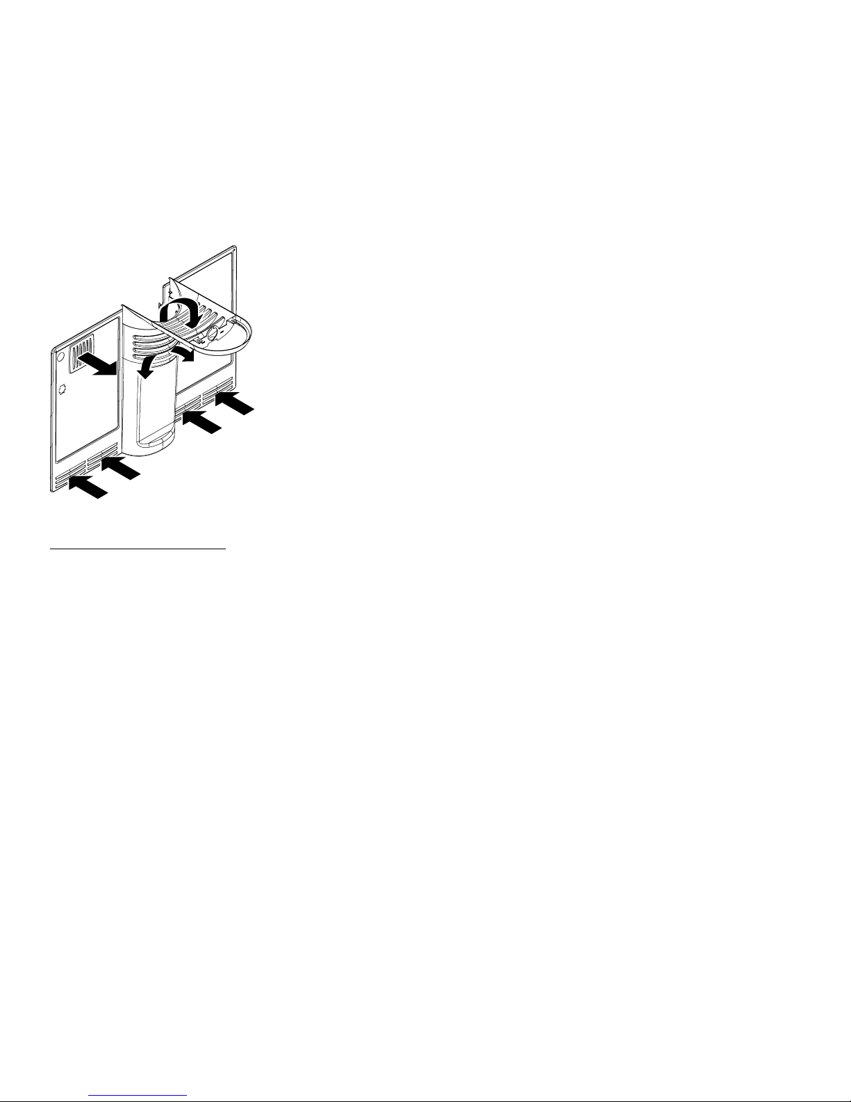
The compressor and dryer are located in the
machine compartment at the bottom, rear of the
unit. The condenser is located under the unit. The
evaporator is located in the freezer compartment
on the back wall.
The capillary is soldered to the compressor
suction line. The capillary is also taped to the
suction line near the dryer. This arrangement
serves as a heat exchanger.
The temperature control and defrost control are
located in the control console. The control
console is located in the top of the fresh food
compartment. The evaporator fan is located in the
freezer compartment behind the air tower.
Electric l Oper tion
The power source provides 115 VAC to the
temperature control. The temperature control is a
thermostatic switch that closes when the fresh
food compartment temperature is higher than the
control setting. When closed, the temperature
control provides 115 VAC to the defrost control.
The defrost control contains a motor/cam
mechanism that switches the defrost control
between defrost mode and cooling mode. When
in cooling mode, the defrost control provides
115 VAC to the compressor, condenser fan, and
evaporator fan. The compressor, condenser fan,
and evaporator fan should always operate at the
same time.
Defrost Oper tion
The automatic defrost function is controlled by the
defrost control. The defrost control contains a
motor/cam mechanism that switches the defrost
control between defrost mode and cooling mode.
The defrost control motor/cam mechanism
operates only when the temperature control
(switch) is closed. After 8 hours of motor/cam
mechanism runtime in cooling mode, the defrost
control switches to defrost mode. The defrost
control will stay in defrost mode, providing 115 VAC
to the heater for 30 minutes of motor/cam
mechanism runtime. The defrost thermostat
switch is mounted on the evaporator and, when
closed, completes the neutral side of the defrost
heater circuit. The defrost thermostat switch
opens when the evaporator temperature raises to
58 °F and closes when the evaporator temperature
lowers to 28 °F. The defrost thermostat switch
typically opens during the defrost cycle, preventing
the heater from defrosting for the full 30 minutes.
The purpose for the 30 minute defrost mode at the
defrost control is to prevent the compressor from
operating and refreezing any water that may be
dripping from the evaporator.
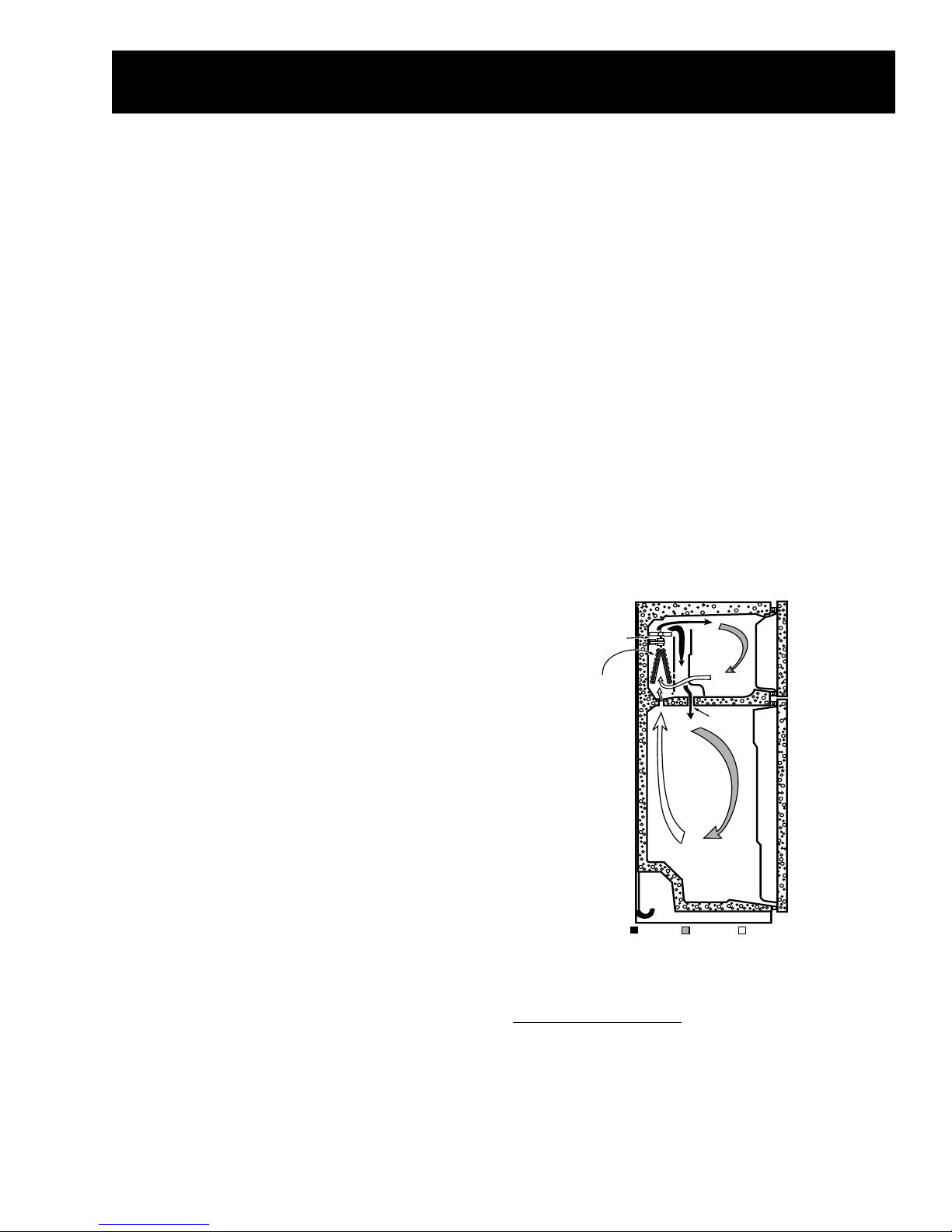
ND103-02B
WARMER AIRMIXED AIR
COLD AIR
DAMPER
FAN
EVAPORATOR
Airflow
Freezer Compartment
Cold air from the evaporator is forced up against
the top of the freezer and the back of the
evaporator cover. It is then discharged through

– 6 –
slots along the air tower at the rear of the freezer
compartment.
Air is circulated by the evaporator fan throughout
the freezer compartment, where it picks up heat
and moisture. The evaporator fan then draws the
warmer, moisture laden air through return louvers
in the bottom of the evaporator cover. The air is
then drawn through the evaporator where heat is
removed and moisture is deposited as frost.
GEA01143
Fresh Food Compartment
Some of the cold air that is being forced against
the top of the freezer and back of the evaporator
cover is diverted through the lower portion of the
freezer air tower and is pushed through the mullion
hole into the damper (in control console).
Air circulates throughout the fresh food
compartment, picking up heat and moisture. The
air is then returned to the evaporator through the
return air ducts located at the top right and left of
the fresh food compartment.

– 7 –
Notes

– 8 –
Mechanical Disassembly
Table of Contents
Door Gasket ............................................................................................................. 9
Doors ......................................................................................................................... 9
Roller ........................................................................................................................ 10
Crisper Drawers ...................................................................................................... 10
Temperature Control .............................................................................................. 10
Defrost Control ....................................................................................................... 11
Light Switches ......................................................................................................... 11
Air Tower and Evaporator Cover .......................................................................... 11
Defrost Thermostat ................................................................................................ 12
Defrost Heater ........................................................................................................ 12
Evaporator (Soldering Method) ............................................................................ 12
Evaporator (LOKRING Method) ............................................................................ 13
Evaporator Fan ....................................................................................................... 14
Condenser Fan ....................................................................................................... 14
PTCR Relay/Overload Cover (Compressor) ........................................................ 15
PTCR Relay (Compressor) ..................................................................................... 15
Overload (Compressor) ......................................................................................... 16
Capacitor (Compressor) ......................................................................................... 16
Compressor ............................................................................................................. 16

– 9 –
Door G sket
The fresh food and freezer doors have magnetic
gaskets that create a positive seal to the front of
the steel cabinet. The magnetic door gaskets are
secured to the fresh food and freezer doors by a
barbed edge that locks into a retainer channel.
Doors
The doors are of one piece construction with foam
insulation. One piece construction provides
superior thermal performance and reduces air
infiltration. During manufacturing, the doors are
filled with hot foam insulation. This may cause
slight distortion or ripples in the inner door liner.
This is a normal condition and is the result of the
insulating process. This process requires doors
to be equipped with vent holes that allow air to
escape when the door is filled with foam. A small
amount of foam may be visible around the vent
holes.
The inner door panels and outer door panels
cannot be separated and must be replaced as an
assembly.
Freezer Door
1. Remove all food from the inner door liner.
Top Hinge
2. Remove 2 screws and the top hinge from the
cabinet.
Note: Do not lose plastic washers on center
hinge pin. Plastic washers are needed for proper
door adjustment.
3. Open the door and lift it off the center hinge pin
to remove.
GEA01150
1. Starting at any corner, pull the old gasket out of
the retainer channel.
2. Soak the new gasket in warm water to make it
pliable.
3. Push the barbed edge of the gasket into the
retainer channel.
GEA01138
Vent Holes

– 10 –
Fresh Food Door
1. Remove all food from the inner door liner.
Note: Do not lose plastic washers on center
hinge pin and lower hinge pin. Plastic washers
are needed for proper door adjustment.
2. Remove pin and washer from center hinge.
3. Open the door and lift it off the bottom hinge to
remove.
Rollers
Rollers at the base of the cabinet enable the
customer to easily move the refrigerator. Cabinet
leveling is done by adjusting the front rollers. To
adjust the front rollers, use a 3/8 in. socket or a
large flat head screwdriver to turn the roller
adjustment screws located behind the base grille.
The rear rollers are not adjustable.
GEA01147
To remove a front roller assembly from the base of
the cabinet:
1. Tilt the cabinet back and place a
3 in. block under the side of the unit.
2. Remove 3 hex head (1/4 in.) screws from the
roller assembly.
3. Loosen the adjustment screw until it
disengages from the assembly and remove
the assembly from the cabinet.
4. Remove the E ring to remove the adjustment
screw from the base channel.
Note: When reinstalling the roller assembly,
position the nut with the flared thread toward the
rear of the unit.
Crisper Dr wers
Unload the bottom shelf before attempting to
remove the storage drawers.
To Remove:
Lift the drawers up slightly while pulling
them past the stop location.
When the door cannot be fully opened:
Remove the drawer that is farthest from the door.
Slide the other drawer toward the middle and
remove it.
Plastic Washer
Fresh Food Door
Hinge Pin
Center Hinge
Bracket

– 11 –
Temper ture Control
1. Remove 3 screws and lower the control
console.
2. Disconnect the harness connector and
remove the control console.
GEA01172
Ground
Wire
Locking
Tabs
Temperature
Adjustment
Knob
Wire
Leads
Ground
Wire
Locking
Tabs
Temperature
Adjustment
Knob
Wire
Leads
Temperature
Control
Temperature
Control
3. Remove knob and clip from temperature
control.
4. Remove styrofoam duct from control console.
5. Remove capillary from plastic sheath.
Note:
To avoid damage to capillary, it may be
necessary to remove wire connectors from defrost
control and from light socket(s).
Temperature control knob clip will be loose when
knob is pulled from temperature control. Use care
to avoid loosing clip. During installation, clip is
installed after knob is pushed on the temperature
control.
6. Press the locking tab back and slide the
temperature control out of the control console.
7. Disconnect 3 wire leads from the temperature
control.
Defrost Control
1. Remove the control console (see Temperature
Control procedure).
2. Disconnect the wiring harness connector from
the defrost control.
GEA01174
Connector
Defrost
Control
Locking Tabs
Connector
Defrost
Control
Locking Tabs
3. Press the locking tabs back and slide the
defrost control out of the control console.
Light Switches
1. Insert a small flat screwdriver under the right
side of the light switch and release the switch
locking tab.
GEA01171
Release Tab
Release Tab
Light Switch
Light Switch
Release Tab
Light Switch
2. Pull the switch out, disconnect the wire leads,
and remove the switch.

– 12 –
Air Tower nd Ev por tor Cover
1. Remove all shelves.
Note: Some models are not equipped with a light
and lens in the light housing. Models without a
light have a plastic cover installed over the light
housing.
2. Remove light lens or plastic cover (models
without light).
3. Remove 2 screws from the bottom of the light
housing.
4. Slide light housing out from 2 pegs.
Disconnect light connector.
5. Remove 2 screws from the air tower.
6. Pull up and remove air tower.
7. Remove 2 screws and evaporator cover with
vent cover.
8. Disconnect ground wire from evaporator cover
and remove evaporator cover from freezer
compartment.
Note:
When installing light housing, ensure that back of
housing is installed on the 2 pegs.
When installing vent on left side of evaporator
cover, vents must direct air down.
Defrost Thermost t
1. Remove the evaporator cover (see Air Tower
and Evaporator Cover procedure).
Caution: The thermostat has a metal clip that
fastens it to the line. Defrost thermostat can be
damaged if handled improperly. Use clip to
remove and install thermostat.
GEA01160
Defrost
Thermostat
Defrost
Thermostat
2. Remove the thermostat from the line.
3. Cut the thermostat lead wires close to the
thermostat to replace.
Defrost He ter
1. Remove the evaporator cover (see Air Tower
and Evaporator Cover procedure).
GEA01163
Defrost
Heater Support
Defrost
Heater Support
Wire LeadWire Lead Evaporator
Drain Probe
Evaporator
Drain Probe Wire LeadWire Lead
2. Remove 2 defrost heater supports and the
evaporator drain probe from the evaporator.
Caution: Do not touch defrost heater glass. Oil
and dirt from hands can cause weak spots on the
glass.
3. Bend the aluminum tabs on the evaporator
back (located at each end of the defrost
heater) and lower the heater out of the
evaporator.

– 13 –
4. Disconnect 2 wire leads and remove the
heater.
Note: Evaporator drain probe assists in defrosting
drain. During assembly, probe must be installed
on evaporator and in drain to prevent drain from
freezing closed.
Ev por tor (Soldering Method)
1. Recover the refrigerant.
2. Remove the evaporator cover (see Air tower
and Evaporator Cover procedure).
3. Remove the defrost thermostat (see Defrost
Thermostat procedure).
4. Remove the defrost heater (see Defrost
Heater procedure).
5. Disconnect ground wire from evaporator and
position all wiring to allow for evaporator
removal.
6. Remove 2 screws that hold the evaporator to
the cabinet.
GEA01164
Screws
Screws
Screws
Caution:
If desoldering the evaporator, HEAT SHIELD P/N
WR49X10025 must be used to prevent damage to
freezer liner.
Protect wiring from heat during desoldering and
resoldering.
To prevent damage to the capillary tube, the
capillary tube must be desoldered first.
7. Desolder the capillary tube from the
evaporator.
8. Desolder the suction line. Use a pair of pliers
to hold the evaporator.
9. Remove the evaporator.
10. Using a file, score the capillary tube just above
the old solder and break the solder covered
section off. This will help prevent the capillary
tube from becoming plugged when resoldering.
11. Position the new evaporator in the cabinet.
Insert the suction line and capillary tube into
the evaporator.
12. Solder the suction line to the evaporator using
silfos.
13. Solder the capillary tube to the evaporator
using silfos.
Note: Evaporator drain probe assists in defrosting
drain. During assembly, probe must be installed on
evaporator and in drain to prevent drain from
freezing closed.
14. Install a replacement dryer.
15. Evacuate and recharge the system using
currently accepted procedures.
Ev por tor (LOKRING Method)
1. Recover the refrigerant.
2. Remove the evaporator cover (see Air Tower
and Evaporator Cover procedure).
3. Remove the defrost thermostat (see Defrost
Thermostat procedure).
4. Remove the defrost heater (see Defrost
Heater procedure).
5. Disconnect ground wire from evaporator and
position all wiring to allow for evaporator
removal.
6. Loosen 2 screws that hold the evaporator to
the cabinet.
Caution: Tubing must be clean and free from
burrs when using LOKRING.
Note: LOKRING connector P/N WR97X10021
must be used. Two LOKRING connectors are
required.
7. Replace the evaporator using the LOKRING
method (see Pub # 31 9067).
Cut the copper lines of the old evaporator as
close as possible to the aluminum evaporator
tubes.
Cut the copper lines of the new evaporator
1 1/8 in. from the edge of the aluminum
evaporator tubes.

– 14 –
Cut
Cut
Here
Here
Cut
Here
GEA01108
OLD EVAPORATOR
Copper
Copper
Evaporator
Evaporator
Lines
Copper
Evaporator
Lines
Cut
Cut
Here
Here
Cut
Here
Cut
Cut
Here
Here
Cut
Here
Cut
Cut
Here
Here
Cut
Here
Aluminum
Aluminum
Evaporator Tubes
Evaporator Tubes
Aluminum
Evaporator Tubes
Aluminum
Aluminum
Evaporator Tubes
Evaporator Tubes
Aluminum
Evaporator Tubes
NEW EVAPORATOR
Copper
Copper
Evaporator
Evaporator
Lines
Copper
Evaporator
Lines
Defrost
Defrost
Thermostat
Thermostat
Here
Here
Defrost
Thermostat
Here
1-1/8 inch
1-1/8
inch
Note: Evaporator drain probe assists in defrosting
drain. During assembly, probe must be installed on
evaporator and in drain to prevent drain from
freezing closed.
8. Install a replacement dryer.
9. Evacuate and recharge the system using
currently accepted procedures.
Ev por tor F n
1. Remove the evaporator cover (see Air tower
and Evaporator Cover procedure).
2. Disconnect the fan motor connector.
3. Carefully pull the fan off the shaft.
4. Remove 2 screws and fan assembly.
5. Remove fan motor.
Note: The position of the fan blade in relation to
the shroud is critical. Refer to figure below for
specifications.
5/16" ± 0.03
Blade tip
1.0" ± 0.05 Target
Motor
Air Flow Orifice
GEA01149
Condenser F n
1. Remove the machine compartment cover.
2. Disconnect the fan motor connector.
3. Carefully push the fan off the motor shaft.
Airflow

– 15 –
GEA01175
Connector
Screws
Fan MotorFan Motor
Fan
Connector
Screws
Fan
4. Remove 2 screws, bracket, and the fan motor.
Caution: During installation, water valve
connector must be tied clear of fan operation.
Note:
The position of the fan blade in relation to the
shroud is critical. Refer to figure below for
specifications.
Ensure that harness connectors are connected
completely and that connector clips are engaged.
If connectors are not connected correctly, they
may vibrate apart.
Housing
Fan
Motor
0.375"
1/2"
Air Flow
0.50" ± 0.05
Bracket
GEA01148
PTCR Rel y/Overlo d Cover (Compressor)
1. Remove the machine compartment cover.
GEA01169
Cover
Tab
Cover
Tab
2. Insert a flat screwdriver under the tab on the
covers top surface, pry up, and remove.
3. Remove the cover.
PTCR Rel y (Compressor)
1. Remove the PTCR relay/overload cover (see
procedure).
GEA01207
2. Pull the PTCR relay straight out from the
compressor.
3. Disconnect the wire leads from the relay.
Airflow

– 16 –
Overlo d (Compressor)
1. Remove the PTCR relay/overload cover (see
procedure).
2. Remove the PTCR relay (see procedure).
3. Pull the overload straight out from the
compressor.
4. Disconnect the wire lead from the overload.
C p citor (Compressor)
1. Remove the machine compartment cover.
GEA01168
Capacitor
Capacitor
Wire Leads
Wire Leads
Capacitor
Wire Leads
2. Disconnect the wire leads from the capacitor.
3. Discharge the capacitor with a screwdriver.
4. Remove 1 screw and the capacitor.
Compressor
Note:
Capillary tube must be clipped to compressor
suction line near the dryer. If capillary tube is not
clipped to suction line, a knocking noise may occur
during compressor operation.
The channel in which the compressor is
mounted must be disengaged from the cabinet to
remove the compressor.
Ensure that harness connectors are connected
completely and that connector clips are engaged.
If connectors are not connected correctly, they
may vibrate apart.
Refer to the compressor replacement instructions
included with the replacement compressor.

– 17 –
Notes

– 18 –
Troubleshooting
Note:
Refer to Operating Characteristics efore
choosing a trou leshooting procedure.
Refer to Schematics.
Refer to Component Locator Views.
Compressor Knock
Capillary tu e not taped to suction line. Check
to see that capillary tube is clipped to the suction
line near the dryer.
Low or No Cooling
Check for the following problems:
1. Condenser dirty/clogged. Unplug unit and
clean condenser and underside of refrigerator.
2. Interior lights remain on. Check to see that
interior lights turn off when door switch is
pressed.
3. Door gasket does not seal. Check for
damaged or leaking door gasket.
4. Compressor does not operate. Go to
Compressor Does Not Operate
troubleshooting.
5. Condenser fan does not operate. Go to
Condenser Fan Does Not Operate
troubleshooting.
6. Evaporator fan does not operate. Go to
Evaporator Fan Does Not Operate
troubleshooting.
7. Evaporator is frosted. Go to Defrost System
Check.
8. Duct is clogged etween freezer
compartment and fresh food compartment.
If fresh food compartment is warm and freezer
is normal or too cold, duct (diffuser) may be
clogged. Duct is accessed by removing air
tower.
9. Refrigeration system faulty. Go to
Refrigeration System Check.
Compressor Does Not Oper te
Check for the following problems:
Note: The defrost control must be in cooling
mode to operate the compressor (provide
115 VAC to the compressor overload). It may be
necessary to manually rotate the defrost control
to cooling mode before checking for voltage at the
compressor overload.
1. 115 VAC not present at compressor
overload. If 115 VAC is not present at the
compressor overload, check for an open
temperature control or an open defrost control
(cooling mode terminals 3 and 4 are closed).
Note: The compressor, condenser fan, and
evaporator fan should always operate at the same
time. If the condenser fan is operating, the
temperature control and defrost control
are OK.
2. Overload open. High heat or high current
draw will cause the overload to open. The
overload should close when the temperature
lowers to normal or when normal current draw
is present.
3. PTCR relay open.
4. Run capacitor faulty.
5. Open wire or faulty connector. Refer to
Schematics.
6. Compressor motor faulty. Check resistance
across the compressor motor. Refer to
Schematics for resistance values.
7. Compressor mechanically stalled.
Condenser F n Does Not Oper te
Check for the following problems:
1. Condenser fan faulty.
2. 115 VAC not present at condenser fan.
The compressor, condenser fan, and
evaporator fan should always operate at the
same time. If the compressor is operating, the
temperature control and defrost control are
OK.
3. Orange wire open on neutral side of
condenser fan. Refer to Schematics.
This manual suits for next models
4
Table of contents
Other GE Refrigerator manuals

GE
GE GCW200YAWC User manual

GE
GE Profile PGCS1RKZ How to use

GE
GE TFX27EM User manual

GE
GE Monogram ZIS360NMC User manual

GE
GE TBF22D Installation instructions

GE
GE CSHS5UGXCSS Safety guide

GE
GE Monogram ZISS480DXBSS User manual

GE
GE PDS20MBWBWW and Operating instructions

GE
GE Profile PFSS5PJZSS Manual

GE
GE Profile GSCF3PGXBB Manual