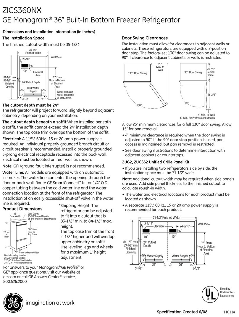
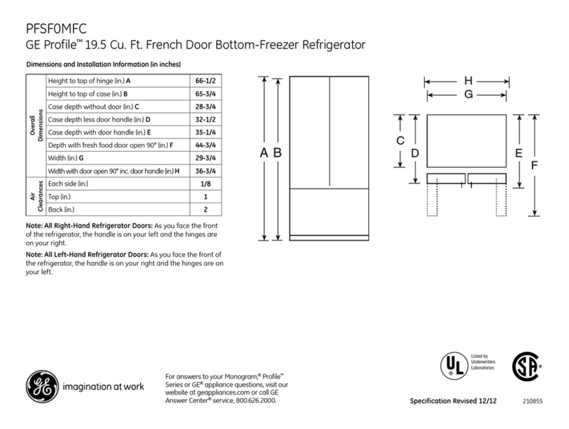
GE Profile PFSS5NJWSS User manual

GE Profile™ Energy Star® 25.1 Cu. Ft. French
Door Bottom-Freezer Refrigerator with External
Dispenser
PFSS5NJWSS
André Leduc Training & Technical Support
mabe CONFIDENTIAL AND PROPRIETARY INFORMATION-NOT FOR PUBLIC DISCLOSURE. January 2008
Pub # 08-MAN-RE-01

2
Table of contents
Table of Contents………………………….….2
Introduction……………………………......3, 4
Technical Data……………….…………...…...5
Defrost Cycle…………………........................6
Liner Protection Mode…. ……………..........7
Control Board Connector Locator……….....8
Airflow………..………………………………..9
Evaporator Fan……………………….....10, 11
Condenser Fan…………………………..12, 13
Fresh Food Damper………………….14,15,16
Inverter………………………………...17,18,19
Inverter Compressor….....…….20, 21, 22, 23
Inverter Troubleshooting Sequence…...…24
EMI Filter………………………………....25, 26
How to Access the Evaporator.…….27 to 34
Defrost Heater.…………………………..…..35
Ice Maker Fill tube…………………………..36
Return Duct Heaters…..…………...37, 38, 39
Articulating Door Mullion
French Door……………………….….…40, 41
Door Closure Mechanism……………...…..42
Ambient Thermistor…......………………....43
Thermistor Replacement…………………..44
Fresh Food Crispers………………………....45
Product Warranty………………………….. 46
Schematic……………………………………..47
EMI Filter Schematic……………………….. 48
How to Disassemble Dispenser Assembly..49
Factory Transport and life test…………....50
mabe CONFIDENTIAL AND PROPRIETARY INFORMATION-NOT FOR PUBLIC DISCLOSURE. January 2008

3
Introduction
*The new Profile bottom mount refrigerators have the following features:
• They are available in 25 and 21 cubic foot capacity with fresh food single or French door
configurations.
• An anti-tip kit will be required for the 21 cu. ft. models.
• They are icemaker ready or have a factory installed icemaker.
• The French door models feature optional filtered external water dispenser.
• Two coil water tanks provide added storage volume with increased surface area for quick
temperature recovery.
• They are ENERGY STAR® rate and have a variable speed inverter compressor and fans on
all models.
• They are equipped with up front, electronic touch temperature controls with digital
temperature display.
• An external "air" thermistor changes the control setting based on ambient condition to
keep the fresh food and freezer compartments at the correct temperature.
• A damper/air inlet assembly in the fresh food section creates more usable space on the top
shelf.
mabe CONFIDENTIAL AND PROPRIETARY INFORMATION-NOT FOR PUBLIC DISCLOSURE. January 2008

4
Introduction (cont.)
• An articulating door mullion attached to the right side door (French door
models), provides a movable center mullion that maximizes access to the fresh
food compartment.
• They are equipped with two self closing freezer drawer cam and lever
mechanisms that automatically pull the drawer shut when it is within 1 inch of
the closed position.
• They feature a BrightSpace™ interior with GE Reveal™ lighting.
• They are available in white, black, bisque, or stainless finish.
• Trim kits are available that allow adding decorator or wood panels to match
kitchen cabinets.
• There is a new nomenclature, (PDSF5NBWABB instead of PDSF25NBWABB). The
cubic foot volume was previously specified as 25, now it only shows as 5.
* Features may vary by model.
mabe CONFIDENTIAL AND PROPRIETARY INFORMATION-NOT FOR PUBLIC DISCLOSURE. January 2008

5
Technical Data
ELECTRICAL SPECIFICATIONS
Temperature control (position 5)………………………………..……………7-(-11)°F
Defrost control (w/no door openings)……………………………...96hrs @ 45 min
Thermistor kilo-ohm resistance……………………………………. @ 0°F…..42.5KΩ
Thermistor kilo-ohm resistance …………………………………… @37°F…….14KΩ
Thermistor kilo-ohm resistance ……………………………..……. .@77°F……..5KΩ
Over temperature thermostat………………………………………………140-110 °F
Defrost thermistor………………………………………………………………..….70 °F
REFRIGERANT CHARGE (R134a)………………………..5.50 ounces/155.9 grams
mabe CONFIDENTIAL AND PROPRIETARY INFORMATION-NOT FOR PUBLIC DISCLOSURE. January 2008

6
Defrost Cycle
The refrigerator utilizes an adaptive defrost cycle that operates a glass
enclosed heater to remove frost from the evaporator. Defrost time has
changed from 60 hours adaptive defrost to 96 hours adaptive defrost.
The control board determines the length of time the heater is energized.
It does this by monitoring the freezer evaporator thermistor. Once the
temperature of the thermistor reaches 70°F, the control cycles the defrost
heater off. A bi-metal safety thermostat provides a backup in the event
the evaporator thermistor fails. The safety thermostat prevents the
temperature from exceeding 140°F.
mabe CONFIDENTIAL AND PROPRIETARY INFORMATION-NOT FOR PUBLIC DISCLOSURE. January 2008

7
Liner Protection Mode
The refrigerator incorporates a liner protection mode for the freezer section.
The freezer evaporator fan will start and run on high speed if the door has
been open for 3 minutes. Air will circulate into the fresh food section if the
damper is in the open position.
This mode is controlled by 2 timers. Timer #1 monitors door-open time. A 3-
minute door-open count begins when the door is opened. If 3 minutes elapse
before the door is closed, the liner protection mode will become active. Once
the door is closed, timer #1 resets and liner protection mode goes into
standby. In standby, normal fan operation resumes and timer #2 begins a 3-
minute door-closed count. If 3 minutes elapse without a door opening, the
liner protection mode will completely deactivate. If a door is opened within
the timer #2 door-closed count, the remaining time in the door-closed count
will be deducted from the timer #1 door-open count.
mabe CONFIDENTIAL AND PROPRIETARY INFORMATION-NOT FOR PUBLIC DISCLOSURE. January 2008

8
Control Board Connector Locator
J10 and J13 - Earth (Ground)
J9 - Defrost heater, fill tube heater, return
duct heaters
J11 -Line(L1)
J7 - FF light thermostat, FZ light thermostat,
dispenser water valve (French door models
only)
J4 - Display board
J3 - Damper
J1 - Fresh food thermistor, freezer thermistor,
freezer evaporator thermistor, ambient
temperature thermistor, model selector
J15 – Inverter
J2 - Fan common, evaporator fan, condenser
fan, mullion bar heater, model selector
mabe CONFIDENTIAL AND PROPRIETARY INFORMATION-NOT FOR PUBLIC DISCLOSURE. January 2008

9
Airflow
• The evaporator fan forces air through the evaporator into
the freezer compartment. Air from the evaporator is also
forced through the electronic damper to the air tunnel outlet,
through the fresh food compartment, and returns to the
evaporator. The fresh food compartment receives chilled air
through an electronic damper at the bottom, rear of the
fresh food compartment. The damper is controlled by the main
control board. When open, the damper allows chilled air from
the freezer to move into the fresh food compartment.
• Air returns from the fresh food compartment to the freezer
compartment via two vents located to the left and right of the
electronic damper.
mabe CONFIDENTIAL AND PROPRIETARY INFORMATION-NOT FOR PUBLIC DISCLOSURE. January 2008

10
Evaporator Fan
Fan speed is selected and maintained by the main control board regulating the
length and frequency of the 13.6 VDC pulse. Temperature can cause some fan
speed variation. Fan speed can vary +/- 5%, depending on the temperature, with
higher temperatures causing slightly higher speeds.
The evaporator fan has a 4-wire connection:
White Wire (DC Common)
The white wire is the DC common wire used for testing. During repairs, DC polarity
must be observed. Reversing the DC polarity causes a shorted motor and/or board.
Red Wire (Supply)
Each motor uses an internal electronic controller to operate the motor. Supply
voltage from the main control board remains at a constant 13.6 VDC.
Blue Wire (Feedback/RPM)
On previous Arctica models, the blue wire reported rpm (speed) information to the
main control board for speed control purposes. On this model, the board does
not require or read any feedback information from the fan motor.
mabe CONFIDENTIAL AND PROPRIETARY INFORMATION-NOT FOR PUBLIC DISCLOSURE. January 2008

11
Evaporator Fan (cont.)
Yellow Wire (Signal)
The yellow wire is the input wire from the main control board. The main control
board provides 6.5 VDC effective voltage for low speed, 8 VDC effective voltage
for medium speed, and 9.5 VDC effective voltage for high speed. The fan
operates in low speed only when the fresh food thermistor is satisfied.
Note: When testing these motors:
• You cannot test with an ohmmeter.
• DC common is not AC common.
• Verify 2 voltage potentials:
a. Red to white - power for internal controller (13.7 VDC)
b. Yellow to white - power for fan (5.5 to 12 VDC)
• Observe circuit polarity.
• Motors can be run for short periods using a 9 volt battery. Connect the white
wire to the negative (-) battery terminal only. Connect the red and yellow wires
to the positive (+) battery terminal.
mabe CONFIDENTIAL AND PROPRIETARY INFORMATION-NOT FOR PUBLIC DISCLOSURE. January 2008

12
Condenser Fan
Condenser fan speed corresponds with compressor speed (low, medium, high) to
minimize pressure variations in the sealed system except when the freezer
temperature is 20°F above the set point (ex:NEW). If this condition exists (such as
during initial startup), the condenser fan operates at super high speed (12VDC
between white and yellow lead)while the compressor operates at medium speed.
The speed of the fan is controlled by the voltage output from the main control board.
Voltage output from the control board to the fan is 13.6 VDC; however, to regulate
the speed of the fan, the main control board uses pulse width modulation (PWM).
When operating, voltage is sent in pulses (much like a duty cycle) as opposed to an
uninterrupted flow. This pulsing of 13.6 VDC produces effective voltage being
received at the motor, which is equivalent to a reduction in voltage.
Fan speed is selected and maintained by the main control board regulating the
length and frequency of the 13.6 VDC pulse.
mabe CONFIDENTIAL AND PROPRIETARY INFORMATION-NOT FOR PUBLIC DISCLOSURE. January 2008

13
Condenser Fan (cont.)
Temperature can cause some fan speed variation. Fan speed can vary +/- 5%,
depending on the temperature, with higher temperatures causing slightly higher
speeds.
Condenser fan speed is controlled by Pulse Width Modulation (PWM), the same
method used to control fan speeds for the evaporators.
mabe CONFIDENTIAL AND PROPRIETARY INFORMATION-NOT FOR PUBLIC DISCLOSURE. January 2008
Only when freezer temperature is
20°F above the set point.
Ex: initial startup.

14
Fresh Food Damper
• The damper assembly consists of a motorized damper that is housed inside the
damper air tower. The damper is connected by a wire harness. The damper
assembly is held in place with a single ¼-in. hex-head screw and 2 pins.
To remove the fresh food damper:
1. Remove the fruit and vegetable crisper drawers and the crisper drawers’ cover and
frame assembly.
Caution: The glass inserted in the deli pan cover and frame may easily
separate. Care should be taken when removing the deli pan cover and
frame assembly.
2. Partially open the deli pan, lift and remove the deli pan cover and frame.
3. Pull the deli pan out to the fully open position
4. Remove the ¼-in. hex-head screw from the air tower cover.
mabe CONFIDENTIAL AND PROPRIETARY INFORMATION-NOT FOR PUBLIC DISCLOSURE. January 2008

15
Fresh Food Damper (cont.)
5. Pull up on the damper assembly then remove the air tower cover.
6. Disconnect the damper motor wire harness.
7. Carefully remove the tape and gasket.
mabe CONFIDENTIAL AND PROPRIETARY INFORMATION-NOT FOR PUBLIC DISCLOSURE. January 2008

16
Fresh Food Damper (cont.)
8. Separate the Styrofoam air tower that houses the damper.
9. Remove the damper from the separated Styrofoam air tower.
mabe CONFIDENTIAL AND PROPRIETARY INFORMATION-NOT FOR PUBLIC DISCLOSURE. January 2008
A complete damper assembly is now available. Part number is WR17X12456

17
Inverter
WARNING: When the refrigerator is plugged in, 120 VAC is always
present at the inverter.
Note: Certain voltmeters will not be able to read voltage output from the
inverter. If there is no voltage or erratic voltage is measured, it does not
necessarily indicate a faulty inverter.
The inverter receives 120 VAC line-in from the power supply. The inverter
converts this single-phase, 60 Hz, 120 VAC into 3-phase, 230 VAC, with frequency
variations between 57 Hz and 104 Hz. This voltage is delivered to the compressor
through 3 lead wires. Each wire will carry identical voltage and frequency.
Note: The compressor leads must be connected to measure voltage output. If the
compressor wires are not connected, or if an open occurs in one of the 3 lead
wires or in the compressor, the inverter will stop voltage output.
When checking the inverter voltage output, connect the test-meter leads to any
2 of the 3 compressor lead wires at the inverter plug (plug should be connected).
The same reading should be measured between any 2 of the 3 wires.
mabe CONFIDENTIAL AND PROPRIETARY INFORMATION-NOT FOR PUBLIC DISCLOSURE. January 2008

18
Inverter (cont.)
The inverter controls the compressor speed by frequency variation and by
Pulse Width Modulation (PWM). Changing frequency and PWM will cause an
effective voltage between 80 and 230 VAC to be received at the compressor.
The frequency can be measured at the J15 connector plug with a proper
digital multimeter.
• Low speed (1710 rpm) - 57 Hz
• Medium speed (2100 rpm) - 70 Hz
• High speed (3120 rpm) - 104 Hz
The inverter receives commands from the main control board. The main
control board will send a PWM run signal from the J15 connector of between
4-6 VDC effective voltage to the inverter (all wires must be connected). The 4-
6 VDC indicate compressor running speed. The inverter will select the
compressor speed (voltage output) based on this signal.
The main control board will only send a run signal to the inverter when the
compressor should be on.
Note: When measuring signal voltage (from the main control board) at the
inverter, a reading of 4-6 VDC will be measured with all wires connected. If
the inverter wiring is disconnected, the board output will measure between
10-12 VDC.
mabe CONFIDENTIAL AND PROPRIETARY INFORMATION-NOT FOR PUBLIC DISCLOSURE. January 2008

19
Inverter (cont.)
The inverter will monitor the compressor operation and if the compressor fails to
start or if excessive current draw (4 amps maximum) is detected, the inverter will
briefly stop voltage output. The inverter will then make 12 consecutive compressor
start attempts (once every 12 seconds). After 12 attempts, if the compressor has not
started, an 8- minute count will initiate. After the 8-minute count, the inverter will
attempt to start the compressor again. If the compressor starts, normal operation
will resume. If the compressor fails to start, this process will be repeated. Removing
power to the unit will reset the inverter count. When power is restored, the
inverter will attempt to start the compressor within 8 seconds.
The inverter has a built-in circuit protection to guard against damage from a failed
or shorted compressor. However, if a failed compressor is diagnosed, order a new
compressor and inverter.
If the compressor fails to start after replacement, replace the inverter.
mabe CONFIDENTIAL AND PROPRIETARY INFORMATION-NOT FOR PUBLIC DISCLOSURE. January 2008

20
Inverter Compressor
Do not attempt to direct-start the compressor. The compressor
operates on a 3-phase power supply. Applying 120 VAC to the
compressor will permanently damage the unit. It is not possible to start
the compressor without an inverter.
The compressor is a reciprocating, variable speed, 4-pole type. It operates on 3-
phase, 80 to 230 VAC within a range of 57 to 104 Hz.
Note: Certain voltmeters will not be able to read voltage output or frequency
from the inverter.
Compressor wattages at various speeds are:
•LOW-65watts
• MED - 100 watts
• HIGH - 150 watts
The compressor is controlled by the inverter, which receives its signal from the
main control board. Varying the frequency to the inverter changes the
compressor speed.
mabe CONFIDENTIAL AND PROPRIETARY INFORMATION-NOT FOR PUBLIC DISCLOSURE. January 2008
Table of contents
Other GE Refrigerator manuals

GE
GE 225D6783P010 User manual

GE
GE RHM 15 User manual

GE
GE GTH18EBT Manual

GE
GE PFSE1N User manual

GE
GE ZISW/B480DX User manual

GE
GE Profile PSW26PSWSS User manual

GE
GE ENERGY STAR GSHF9NGYWW Assembly instructions

GE
GE Monogram ZIC360N RH Guide
GE
GE ESHF5MGXGEWW Safety guide

GE
GE Profile ENERGY STAR PFSF5NFW Manual

GE
GE GSCS3KGYSS Manual

GE
GE Profile PSSF3RGZ User manual

GE
GE Profile PSS29NSTSS Manual

GE
GE GSH22JFZ Manual

GE
GE TFG20JRXA User manual

GE
GE GE Profile Arctica PSS25MGN User instructions

GE
GE Monogram ZIF360NHXH User manual

GE
GE Profile PDS20MFW Manual

GE
GE Profile PSHS6MGZSS Assembly instructions

GE
GE 22 User manual