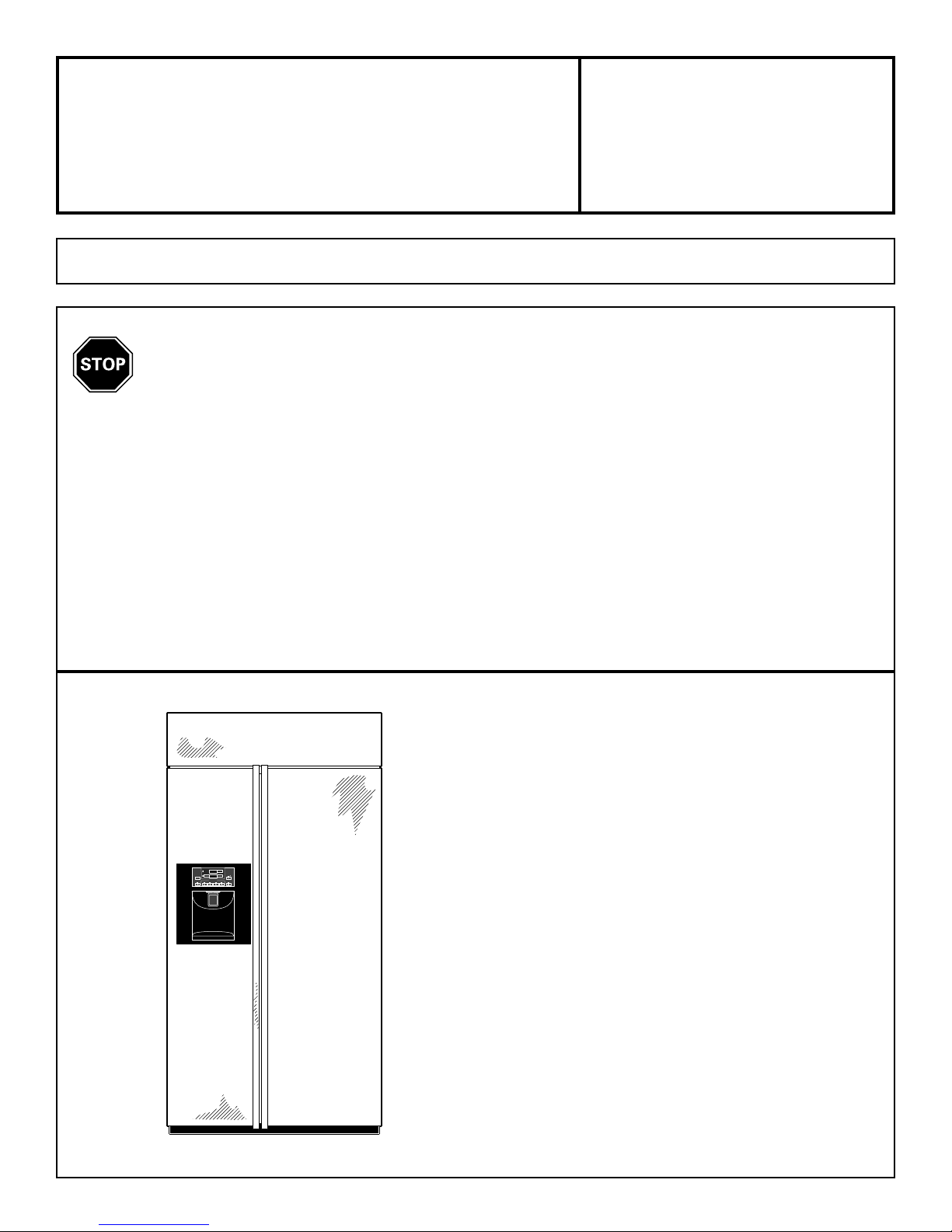
GE Profile PSB42LGRBV Instruction Manual

Installation
Instructions Built-In
Side-By-Side
Refrigerators
If you have questions, call 800-GECARES or visit our website at: www.GEAppliances.com
BEFORE YOU BEGIN
Read these instructions completely and
carefully.
IMPORTANT– Observe all
governing codes and ordinances.
• Note to Installer – Be sure to leave these instructions
for the consumer’s and local inspector’s use.
• Note to Consumer – Keep these instructions with
your Owner’s Manual for future reference.
• Skill Level – Installation of this refrigerator requires
basic mechanical, carpentry and plumbing skills.
Proper installation is the responsibility of the installer.
Product failure due to improper installation is not
covered under the GE Appliance Warranty. See
warranty information.
READ CAREFULLY.
KEEP THESE INSTRUCTIONS.
Side-By-Side Refrigerators:
PSB42LGRWV
PSB42LGRBV
PSB42LSRBV
ADJUSTTEMPERATURE
COLDER
REFRIGERATOR 37°FISRECOMMENDED
0°FIS RECOMMENDED
FREEZER
COLDER
DISPLAY
TEMP
DOORALARM WATER CRUSHED
ICEDISPENSER
CUBED QUICKICE
WARMER
WARMER LOCK
RESETFILTER
HOLD3 SECS
LIGHT
HOLDFOR
3SECS
TOACTIVATE

CONTENTS
Planning Guide
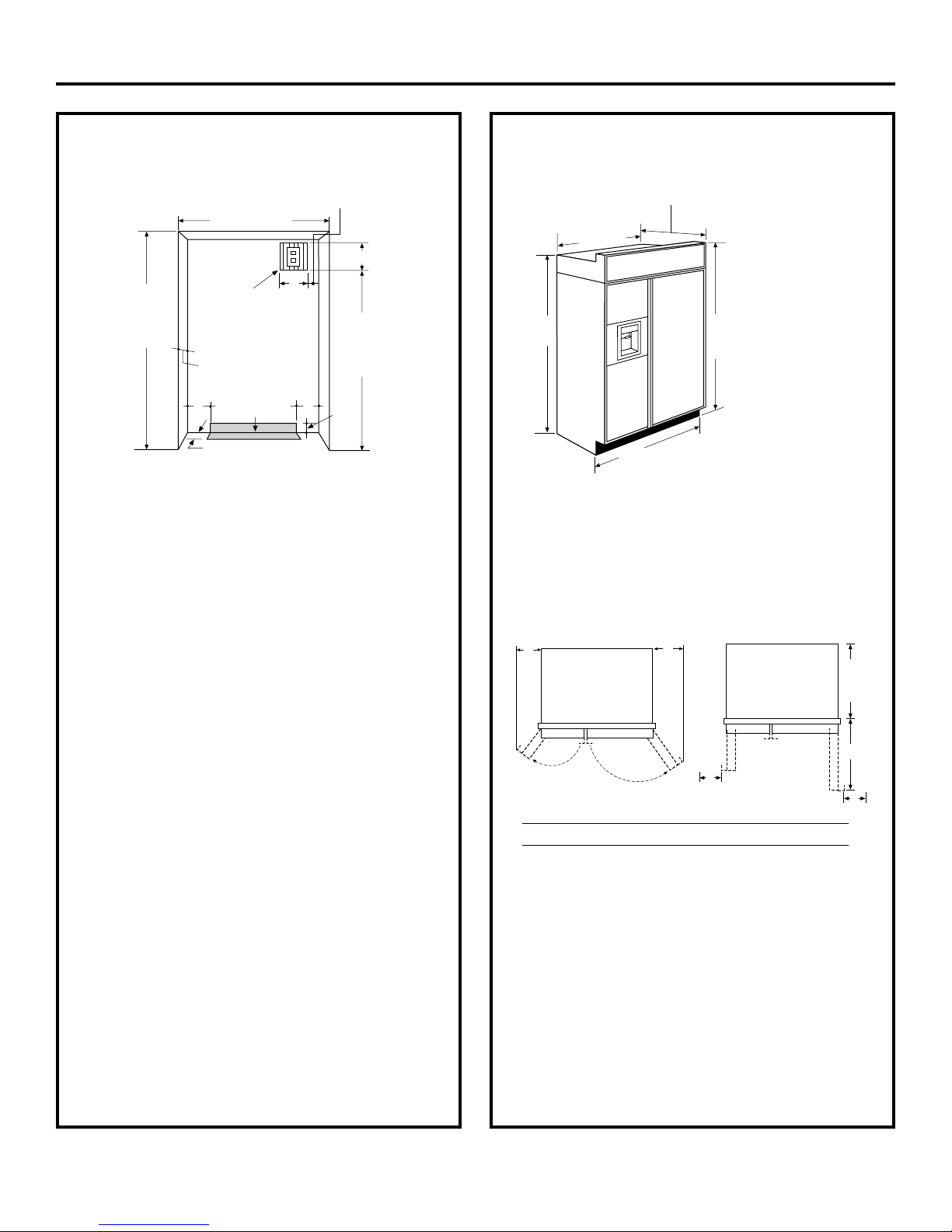
The Installation Space . . . . . . . . . . . . . . . . . . . 3
Dimensions and Clearances . . . . . . . . . . . . . . 3
130° Door Swing . . . . . . . . . . . . . . . . . . . . . . . . 4
90° Door Swing . . . . . . . . . . . . . . . . . . . . . . . . . 5
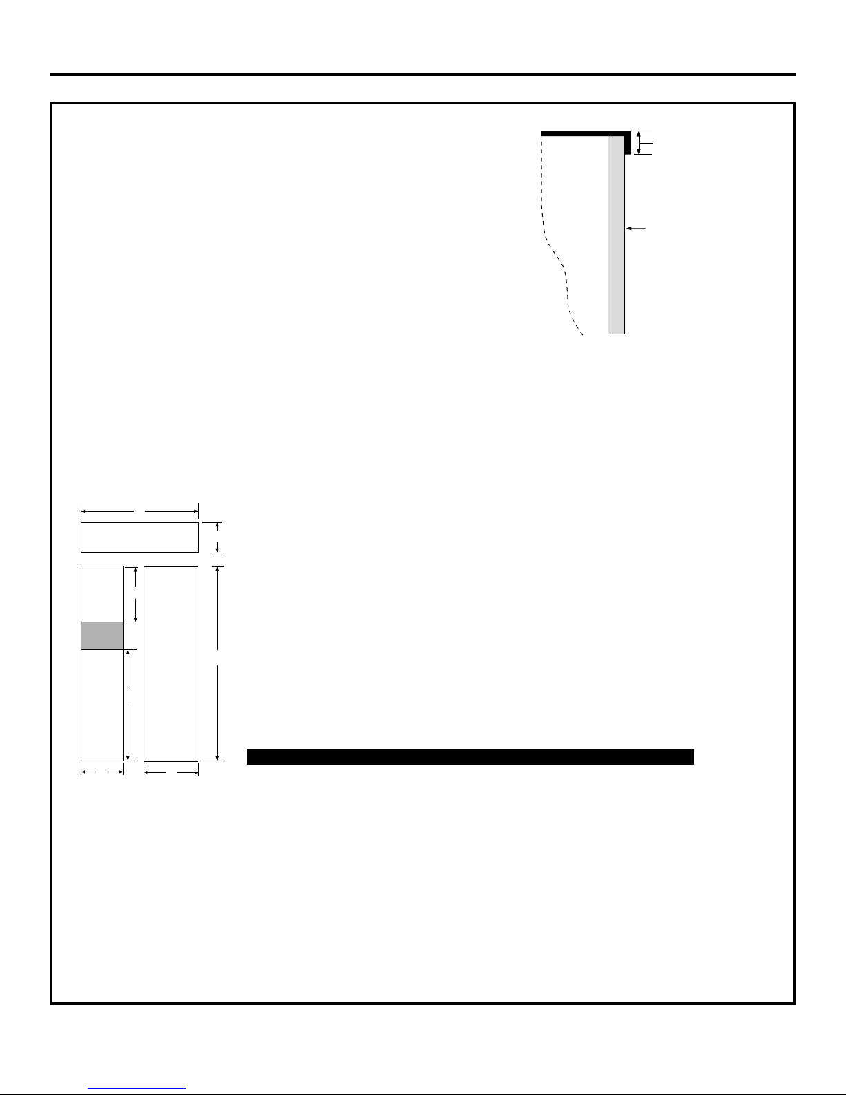
Customization Basics . . . . . . . . . . . . . . . . . . . . 6
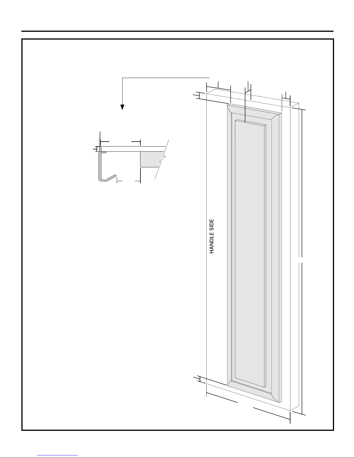
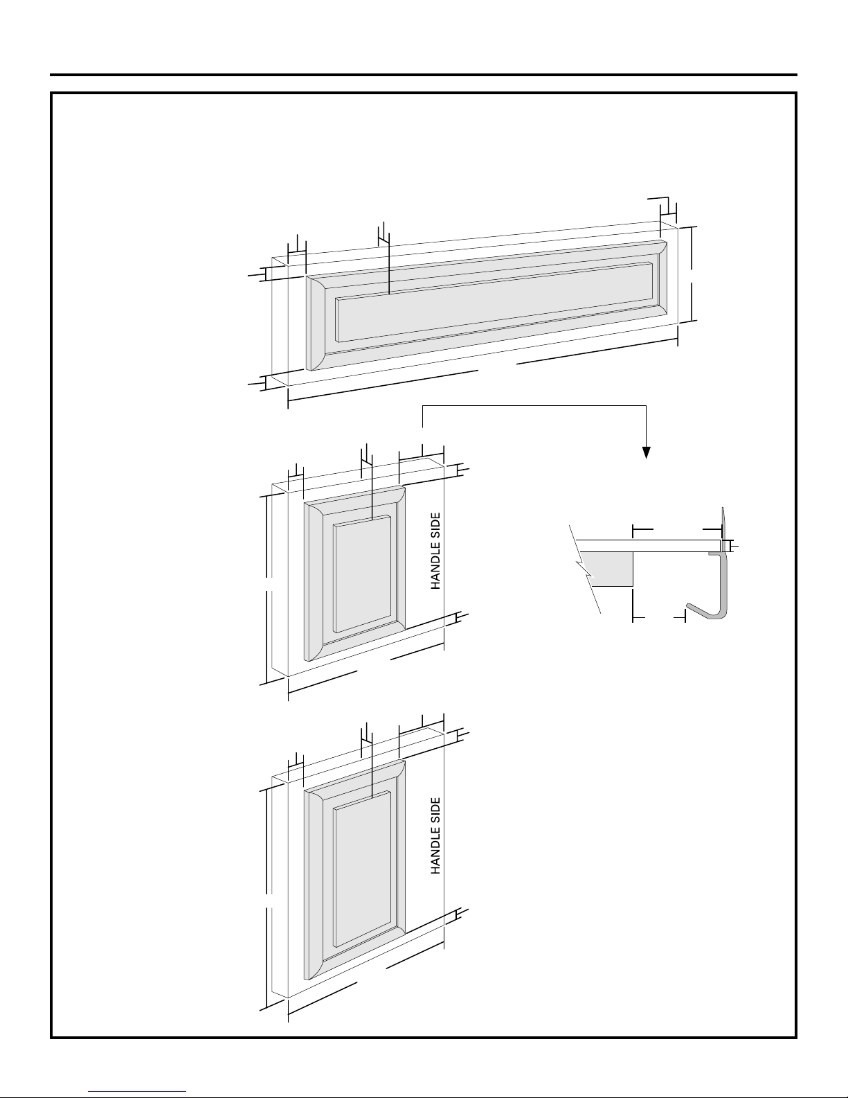
1/4" Framed Panel Dimensions . . . . . . . . . . . . 7
3/4" Custom Panel Dimensions . . . . . . . . . . . . 8
3/4" Custom Wood Panels . . . . . . . . . . . . . . . . 9
3/4" Custom Wood Panels . . . . . . . . . . . . . . . 10
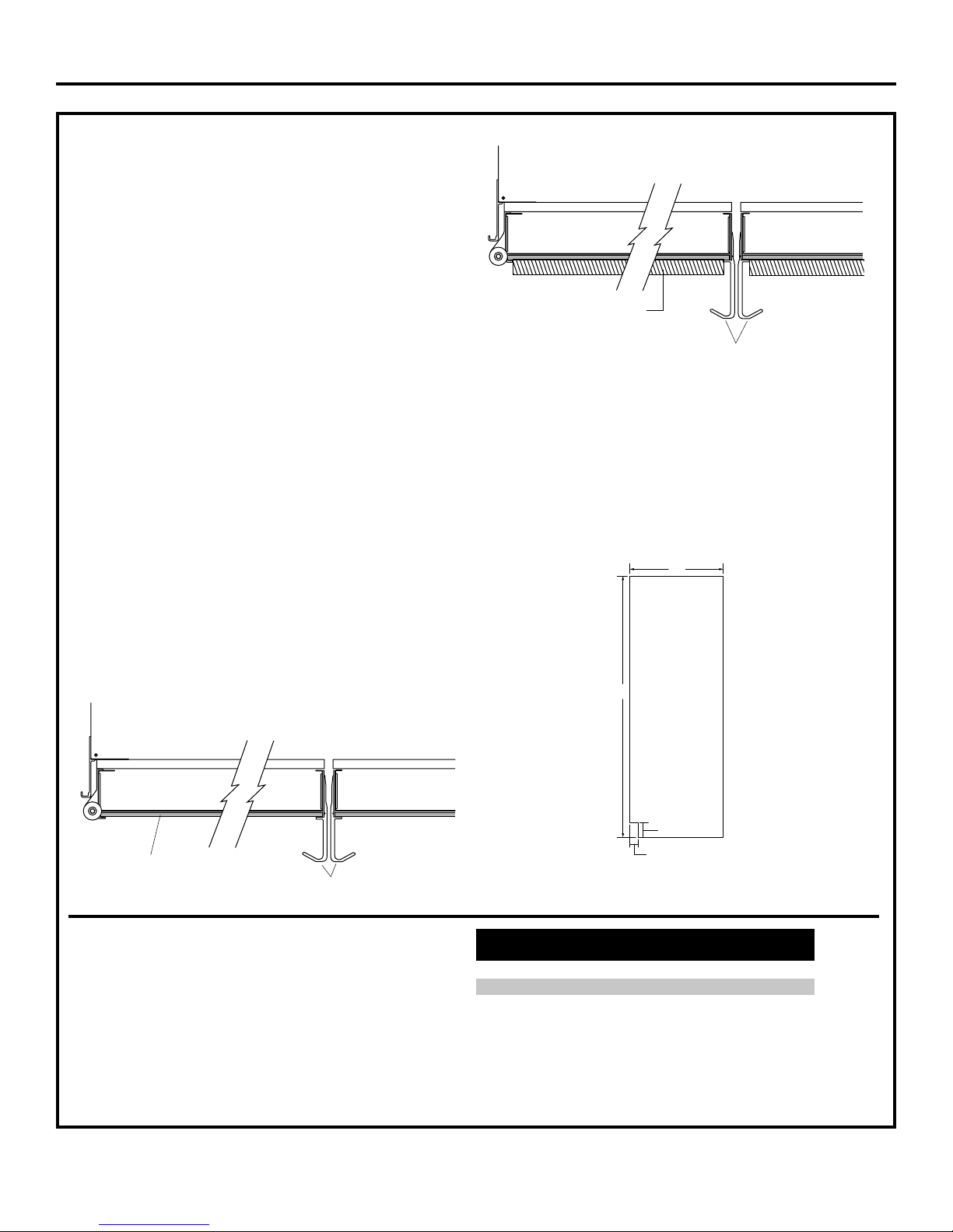
Side Panels . . . . . . . . . . . . . . . . . . . . . . . . . . . 11
Installation Instructions
Tools, Hardware, Materials . . . . . . . . . . . . . . 11
Grounding the Refrigerator . . . . . . . . . . . . . . 11
Step 1, Remove Packaging . . . . . . . . . . . . . . 12
Step 2, Install Water Line . . . . . . . . . . . . . . . 13
Step 2A, RO Water Line . . . . . . . . . . . . . . . . . 14
Step 3, Install Side Panels . . . . . . . . . . . . . . . 14
Step 4, Install Anti-Tip Brackets . . . . . . . . . . 14
Step 4A, Alternate Anti-Tip Precautions. . . . 14
Step 5, Connect Power. . . . . . . . . . . . . . . . . . 15
Step 6, Move Into Installation Space . . . . . . 15
Step 7, Level Refrigerator . . . . . . . . . . . . . . . 15
Step 8, Secure Refrigerator to Cabinets . . . 16
Step 9, Adjust Door Swing . . . . . . . . . . . . . . 16
Step 10, Install Grille Panel . . . . . . . . . . . . . . 16
Step 11, Install Door Panels . . . . . . . . . . . . . 17
Step 12, Connect Water Supply . . . . . . . . . . 18
Step 13, Turn on the Power . . . . . . . . . . . . . . 18
Step 14, Start Icemaker . . . . . . . . . . . . . . . . . 19
Step 15, Install Toekick . . . . . . . . . . . . . . . . . 19
Step 16, Inspect Final Installation . . . . . . . . . 19
Safety Information
CAUTION:
Due to the weight and size of this refrigerator, and to
reduce the risk of personal injury or damage to the
product - a minimum of 4 people are required to bring
the unit into the home and 2 people are REQUIRED FOR
PROPER INSTALLATION.
WARNING:
• These refrigerators are top-heavy and must be
secured to prevent the possibility of tipping forward.
Anti-Tip protection is required. See page 14, Step 4
for details.
• Use this appliance only for its intended purpose.
• Immediately repair or replace electric
power supply cords that become frayed or
damaged.
• Set the Master Power switch to the O(OFF)
position before cleaning or making repairs.
• Repairs should be made by a qualified service
technician.
For Profile™ local service in your area, 1-800-432-2737.
For Profile™ service in Canada, 1-888-880-3030
For Profile™ Parts and Accessories, call
1-800-626-2002.
www.GEAppliances.com
2

Design Guide
3
THE INSTALLATION SPACE
Water And Electrical Locations
The opening must be prepared with the electrical and
water supply located as shown.
The cutout depth must be 24".
The refrigerator will project forward, slightly beyond
adjacent cabinets, depending on your installation.
Additional Specifications
• A 120 volt, 60Hz, 15 or 20 amp power supply is
required. An individual properly grounded branch
circuit or circuit breaker is recommended. Install a
properly grounded 3-prong electrical receptacle
recessed into the back wall. Electrical must be
located on rear wall as shown.
Note: GFI (ground fault interrupter) is not
recommended.
• Water line can enter the opening through the floor
or rear wall. The water line installed should be 1/4"
O.D. copper tubing or GE SmartConnect™ tubing
between the cold water line and water connection
location. The line should be long enough to extend
to the front of the refrigerator. Installation of an
easily accessible shutoff valve in the water line is
required.
DIMENSIONS AND CLEARANCES
Allow minimum clearances for Freezer door
(Dimension A) and Fresh Food door (Dimension B) for
a full 130 degree door swing and to allow for drawer
removal.
4" minimum clearance is required when door swing
is adjusted to 90 degrees. If the 90 degree door stop
position is used, drawer access is maintained, but
drawer removal is restricted.
See illustrations pages 4 and 5 to determine door
swing interaction with adjacent cabinets or
countertops.
• Depth including
handles, 26-7/8".
*Shipping height.
The front height
may be adjusted
from 83-1/2" to 84-1/2"
by adjusting front and
rear leveling legs a
maximum of 1".
*The finished cutout width must be:
41-1/2" for 42" models
42" Frame-to-Frame
41"
Case Width
25-3/8" Case Depth
*81-3/4"
at Rear *84" From
Floor to
Top Frame
*Finished Width
Electrical
Area
84 1/2" max
83 1/2" min
Finished
Opening 74"
From Floor
to Bottom
of Electrical
24"
5" 5" 3 1/2"
Water Supply
3 1/2"
3"
7"
5"
Product Clearances
These refrigerators are equipped with a 2 position
door stop. The factory set 130° door swing can be
adjusted to 90° if clearance to adjacent cabinets or
walls is restricted.
130° Door Swing 90° Door Swing
B
A23-7/8"
Behind
Frame
C
D
D
Models A B C D
42" 12-3/16" 16" 24" 4"

1/2"
1"
3/4" Custom Panel
(Nominal Size)
1/4"
1/2" 3/4" 2"
1-1/4"
1-1/2"
1-3/4" 3"
2-1/4"
2-1/2"
2-3/4"
1/4"
1/2"
3/4"
Fresh Food
Door
23-7/8" From
Rear of
Refrigerator
1"
Refrigerator
Case
Trim
3/4"
1/4"
1"
Design Guide
4
Top View
130° Door Swing
(factory setting)
Scale 1:1

847Dia36
1/2"
1/4"
1/2"
3/4"
1"
1-1/4"
1-1/2"
23-7/8"
From Rear of
Refrigerator
3/4" Custom Panel
(Nominal Size)
Case Trim
Refrigerator
Fresh Food
Door
Backer Panel
3/4"
1/4"
1"
Design Guide
5
Top View
90° Door Swing
(optional setting)
Scale 1:1

CUSTOMIZATION BASICS:
Framed Or Custom Panels
Stainless Steel Wrapped Models
42" wide model - PSB42LSRBV
Trimmed Models
42" wide models - PSB42LGRWV, PSB42LGRBV
Stainless Steel Wrapped Refrigerators
Stainless Steel wrapped refrigerators have wrapped
doors and grille panels, and beveled edges. These
models are shipped ready for installation.
Door Handles
The handles can be used to accommodate both framed
or custom panels.
NOTE: For 3/4" custom panels, please refer to diagrams
on page 9 for optimum handle clearance.
Trimmed Refrigerators
Trimmed refrigerators are designed to be customized
with decorative panels. Field installed custom door and
grille panels are required. You may install 1/4" thick
custom panels from your cabinet manufacturer. The
decorative panel slides into the factory installed trim.
Or, order black and white accessory panels from your
Profile™dealer.
Side Panels
Side panels must be used whenever the sides of the
refrigerator will be exposed.
Accessory Panels
White and Black accessory panels are available from
your Profile dealer. Panels are cut to size and ready to
install.
Models White Black
Acrylic Acrylic
PSB42LGRWV PSPK42RWW
PSB42LGRBV PSPK42RBB
Door Handles
3/4" Custom Panel
24"
*84"
*3" to 4"
2-9/16"
Design Guide
6
Framed Panel Door Handles

1/4" FRAMED PANEL DIMENSIONS
If you choose to install framed panels, they must be cut
to the dimensions shown. The panels will slide into the
frame on the door and grille.
IMPORTANT NOTE: Maximum weight for Fresh
Food panel is 70 pounds and 30 pounds total for
Freezer panels.
The framed panel must be 1/4" nominal thickness
to fit the dispenser trim.
IMPORTANT NOTE: Dispenser Trim
The refrigerator is supplied with factory installed dispenser trim.
•If panel is less than 1/4" thick a noticeable gap will be created
around the dispenser trim. Foam tape may be applied on the door to
improve the fit.
•If panel is more than 1/4" thick, the panel will not fit behind the trim.
E
D
F
A
B
Grille Panel
C
Dispenser
Cutout
Freezer
Panel Fresh Food
Panel
G
1/4"
Panel
Door
5/16"
Trim
Reveal
Design Guide
7
Front Panel Dimensions (in inches)
ABCDEFG
42" Models 39-15/16 10-3/4 67-7/8 16-7/16 22-11/32 17-13/16 35-5/32

3/4" CUSTOM PANEL DIMENSIONS
For a more custom appearance, 3/4" custom panels
may be installed on trimmed models. The custom panel
must be cut to dimensions specified below. The custom
panel then slides into the trim with the same procedure
described on page 17.
NOTE: Left-to-right offset is not always
equal to top-to-bottom offset.
.250 + .750 = 1.000 Maximum Total Panel Thickness
IMPORTANT NOTE: Maximum total weight for assembled
Fresh Food panel is 70 pounds and 30 pounds total for
Freezer panels.
3/4"
Custom
Panel
1/4"
Backer
Panel
Door
3/4"
Design Guide
8
CustomPanel
BackerPanel
E
D
F
A
B
Grille Panel
C
Dispenser
Cutout
Freezer
Panel Fresh Food
Panel
G
Front Panel Dimensions (in inches)
ABCDEFG
42" Models 39-15/16 10-3/4 67-7/8 16-7/16 22-11/32 17-13/16 35-5/32

3/8"
3-1/8"
5/16"
1" Thick Max.
or 3/4" Plus
1/4" Backer
67-7/8"
2-1/2"
3-1/8" Min.
1/4" Max.
22-11/32"
5/16"
Required for Optimal
Handle Clearance
Design Guide
9
3/4" CUSTOM WOOD PANELS ONLY
Fresh Food Panel

3/8" 3-1/8"
5/16"
1" Thick Max.
or 3/4" Plus
1/4" Backer
17-13/16"
2-1/2"
3-1/8" Min. 1/4" Max.
16-7/16"
5/16"
Required for Optimal
Handle Clearance
3/8"
3-1/8"
5/16"
1" Thick Max.
or 3/4" Plus
1/4" Backer
35-5/32"
16-7/16"
5/16"
1" Thick Max.
or 3/4" Plus
1/4" Backer
39-15/16"
5/16"
1/4"
10-3/4"
5/16"
1/4"
Design Guide
10
3/4" CUSTOM WOOD PANELS ONLY
Grille Panel
Freezer Panel
Freezer Panel

Installation Instructions
SIDE PANELS
Side panels must be
used whenever the
sides of the refrigerator
will be exposed. The
1/4" side panels will slip
into the side case trim.
Order the side panels
from the cabinet
manufacturer.
*Depending on
installation height.
FLOORING
For proper installation, this refrigerator must be
placed on a level surface of hard material that is at
the same height as the rest of the flooring. This
surface should be strong enough to support a fully
loaded refrigerator, or approximately 700 lbs.
NOTE: Protect the finish of the flooring. Cut a large
section of the cardboard carton and place under the
refrigerator where you are working.
TOOLS REQUIRED
•Tinsnips to cut banding
•Stepladder
•Bucket
•Level
•Appliance dolly
•Tubing cutter
•Flathead screwdriver
•1/2" open-end wrench
•#2 Phillips screwdriver
•Drill and appropriate bits
•7/32", 1/2" socket
•Safety glasses
•7/16" open-end wrench
•Pliers
HARDWARE SUPPLIED
•Water filter bypass plug
•Anti-Tip brackets
•1/4" nut and ferrule
•Dispenser trims for 1/4" and 3/4" custom panels
MATERIALS REQUIRED
•36" long, 2" x 4" wood block for Anti-Tip bracket
installation
•Special 3M Dual Lock adhesive strips for 1/4" side
panels (if installing side panels)
•#12 or #14 wood screws for Anti-Tip bracket
•1/4" O.D. copper water line tubing or GE
SmartConnect™refrigerator tubing kits
•Water shutoff valve
•Custom panels for doors and grille panel
•Screws to secure refrigerator to cabinets
GROUNDING THE REFRIGERATOR
IMPORTANT - (Please read carefully)
FOR PERSONAL SAFETY, THIS APPLIANCE MUST BE
PROPERLY GROUNDED.
The power supply cord of this appliance is equipped
with a three-prong (grounding) plug which mates with
a standard three-prong (grounding) wall receptacle to
minimize the possibility of electric shock hazard from
this appliance.
Have the wall outlet and circuit checked by a
qualified electrician to make sure the outlet is
properly grounded.
Where a standard 2-prong wall outlet is encountered,
it is your personal responsibility and obligation to
have it replaced with a properly grounded 3-prong
wall outlet.
DO NOT, UNDER ANY
CIRCUMSTANCES, CUT
OR REMOVE THE THIRD
(GROUND) PRONG
FROM THE POWER CORD.
DO NOT USE AN ADAPTER PLUG TO CONNECT THE
REFRIGERATOR TO A 2-PRONG OUTLET.
DO NOT USE AN EXTENSION CORD WITH THIS
APPLIANCE.
11
24"
*84"
*3" to 4"
2-9/16"

Installation Instructions
STEP 1 REMOVE PACKAGING
CAUTION:Refrigerator is Top
Heavy –be careful when moving. When using an
appliance dolly, handle from Freezer side only.
•Carefully cut banding at the top and bottom, remove
outer carton.
•Slide out rear corner posts (2).
•Slide carton off top of cabinet.
NOTE: DO NOT LAY CABINET DOWN IN ORDER TO
REMOVE SKID!
•The unit is secured to the skid with 6 Phillip screws
and six 1/2" bolts.
•Remove all 6 Phillip screws that secure metal
brackets to the refrigerator.
•Remove the three 1/2" nuts and washers from the
Freezer side.
•Tilt unit up on Freezer side toward Fresh Food side.
•Push bolts down, remove metal bracket from
Freezer side.
•Slide the appliance dolly underneath the Freezer
side.
•Using corner posts (2 on front corners) to prevent
damage, secure unit to appliance dolly.
NOTE: If corner posts are too long, cut the posts to a
shorter length.
•Lift the unit off the skid with the appliance dolly.
•Remove toekick taped to the top of the unit.
•Set toekick aside for final installation.
CAUTION:DO NOT ATTEMPT TO
ROLL OR DRAG UNTIL UNIT IS OFF SKID.
CAUTION:MAKE SURE THE
WATER LINE IS CLEAR OF APPLIANCE
DOLLY TO AVOID DAMAGE.
12
Remove
Tie Downs
Toekick Taped to
Top of Unit

Installation Instructions
STEP 2 INSTALL WATER LINE
•A cold water supply is required for automatic
icemaker operation. The water pressure must
be between 40 and 120 psi.
•Route 1/4" O.D. copper tubing or GE
SmartConnect™tubing between cold water
line and the water connection location.
•Tubing should be long enough to extend to the
front of the refrigerator. Allow enough tubing
to accommodate bend leading into the water line
connection.
NOTE: The only GE approved plastic tubing is
supplied in the GE SmartConnect™refrigerator
tubing kits. Do not use other plastic water supply
line, because the line is under pressure at all times.
Certain types of plastic may crack or rupture with
age and cause water damage to your home.
GE SmartConnect™refrigerator tubing kits are
available in the following lengths:
2' (.6m) WX08X10002
6' (1.8m) WX08X10006
15' (4.6m) WX08X10015
25' (7.6m) WX08X10025
Shut off the main water supply.
Turn on the nearest faucet long enough to purge all
the water from the line.
•Install a shutoff valve between the icemaker water
valve and cold water pipe in a basement or cabi-
net. The shutoff valve should be located where it
will be easily accessible.
NOTE: It is best to install the valve into a vertical
water pipe. If you install the valve into a horizontal
water pipe, make the connection at the top or side to
avoid drawing off any sediment from the water pipe.
•Drill a 1/4" hole in the water pipe.
•Fasten the shutoff valve to the pipe with pipe
clamp.
•Tighten the clamp screws until the sealing washer
begins to swell. Do not OVER TIGHTEN.
•Place a compression nut and ferrule (sleeve) onto
the end of the tubing and connect it to the shutoff
valve. Make sure the tubing is fully inserted into the
valve and ferrule is tightened.
•Turn on the main water supply and flush debris.
Run about a quart of water through the tubing
into a bucket. Shut off water supply at the
shutoff valve.
NOTE: Saddle type shutoff valves are included in
many water supply kits. Before purchasing, make
sure a saddle type valve complies with your local
plumbing codes.
13
Floor
Copper Tubing,
or GE SmartConnect™Tubing
Saddle Type
Shutoff Valve
Compression Nut
Ferrule
(Sleeve)
Outlet Valve
Packing Nut
NOTE: Commonwealth of Massachusetts Plumbing
Codes 248CMR must be adhered to. Saddle valves
are illegal and use is not permitted in
Massachusetts. Consult with your licensed
plumber.

Installation Instructions
STEP 3 INSTALL SIDE PANELS
SKIP THIS STEP WHEN NOT USING SIDE PANELS
If you are using 1/4" side panels, they should be
inserted into the case trim. Fasten the panels to the
refrigerator with the 3M Dual Lock adhesive strips
before setting refrigerator in place.
STEP 4A ALTERNATE ANTI-TIP
PRECAUTIONS
SKIP THIS STEP WHEN USING ANTI-TIP BRACKETS
All Profile built-in refrigerators are top heavy.
They must be secured to prevent the possibility of
tipping forward. Use this alternative method to
secure the refrigerator whenever steel wall studs
are encountered.
STEP 2A WATER LINE
INSTALLATION WITH
A REVERSE OSMOSIS
SYSTEM
SKIP THIS STEP WHEN NOT USING AN RO SYSTEM
NOTE: If the water supply to the refrigerator is from a
Reverse Osmosis Water System use the refrigerator’s
filter bypass plug. Using the refrigerator’s water filtra-
tion cartridge with the RO filter can result in hollow
ice cubes.
•Open the top grille to view the filtration cartridge.
Rotate the filtration cartridge clockwise until
removed.
•Insert filter bypass plug. Rotate the filter bypass plug
counterclockwise until tightly secured in place.
STEP 4
INSTALL ANTI-TIP BRACKETS
WARNING:
The refrigerator is top-heavy and must be secured to
prevent the possibility of tipping forward.
•Cut a 2" x 4" wood
block 36" long,
and secure the
block to the
mounting
brackets
provided, using #12
or #14 wood screws.
•Secure the bracket
with a wood block to
the back wall so that it is 82"
(or the rear installation height) from the finished floor.
14
Rotate Clockwise
To Remove
Water Filter
Master
Power Switch
Install (4) 1-1/2" Drywall Screws
Through Trim and Into Soffit
or 3/4" Min. Wood Brace
Top Case Trim Side View
Top Case Trim
3/4"
Min.
•Adjust height of refrigerator to match installation
cutout opening 83-1/2" to 84-1/2". The refrigerator
must be level and plumb with cabinets. The top
case trim at the front is 2-1/8" higher than the rear
and will overlap upper cabinets or cabinet trim.
•Open grille panel to access the top case trim.
•Use a 3/16" bit to drill 4 evenly spaced clearance
holes through the metal top case trim.
•Use a 1/16" bit to drill pilot holes through the
metal clearance holes and into wood soffit. The
holes should be centered in the soffit or a 3/4"
minimum wood brace. The brace spanning the
enclosure must be securely fastened to cabinets
on both sides.
•Install four, 1-1/2" drywall screws into the pilot holes.
ANTI-TIP
PRECAUTIONS
Positioned
Anti-Tip
Bracket
Wall Stud
(Behind
Drywall)
Wood Screws
Mounted into
Vertical
Wood Studs
36"

Installation Instructions
STEP 7 LEVEL REFRIGERATOR
All models have 4-point leveling. The front and back
are supported by leveling legs. Both are accessible
from the front of the refrigrator.
•To level the back of the refrigerator, turn the 1/2"
hex nut located above the front wheels. Turn clock-
wise to raise or counterclockwise to lower the
refrigerator.
•For front leveling, use a 7/16" open-end wrench.
•Adjust height of refrigerator to match installation
cutout opening 83-1/2" to 84-1/2". The refrigerator
should be level and plumb with cabinets.
CAUTION:
The rear
leveling legs
and front
leveling legs
are limited to
a maximum
height adjust-
ment of 1". If
the installation
requires more
than 84-1/2"
height, the
installer should
elevate the refrigerator on a sheet of plywood or
runners. Cabinet trim could be added across the top
of the opening to shorten the opening.
If you attempt to raise the refrigerator more than 1"
you will damage the front and rear leveling legs.
STEP 5 CONNECT POWER
•Connect refrigerator power cord plug to a properly
grounded receptacle. Set the Master Power switch
to the I(ON) position.
•Check to make sure power to refrigerator is on by
opening refrigerator door to see if interior lights
are on.•After power has been established turn
the Master Power switch to the
O (OFF) position.
STEP 6 MOVE INTO
INSTALLATION SPACE
•Slide the unit into the installation space.
•Place excess slack in the power cord on top of the
refrigerator.
•Use care to ensure the power cord is not pinched
behind the unit.
15
Raise
Grille
Panel
Water Filter
Master
Power Switch
Hex Nut Adjusts
Rear Wheels
Leveling Leg
Height
from
Floor to
Bottom
of Wood
Block
82"

STEP 8 SECURE REFRIGERATOR
TO CABINETS
Whenever possible, perform this step for anti-tip
security.
The refrigerator must be secured to prevent tipping.
•Raise the grille panel to access case trim.
•Drill a hole into the trim below the hinge. Drive
a screw through the trim and into the adjacent
cabinet.
•Follow the same procedure on the opposite side.
Drive Screws
Through Case Trim Into
Adjacent Cabinets
Raise Grille Panel
to Stop Position
STEP 9 ADJUST DOOR SWING
SKIP THIS STEP IF DOOR OPENING IS SATISFACTORY
FOR YOUR INSTALLATION SITUATION.
NOTE: This refrigerator has a 2-position door stop.
When space does not allow the door to swing open
fully to 130°, you may change the door swing to a 90°
opening.
•Open the door to view the bottom hinge. Note the
door stop pin location. The pin is factory installed in
the 130°position.
•Partially close the door. From above, use a Flat-Head
screwdriver to unscrew the door stop pin and rein-
stall into the 90°position.
90˚
130˚
Hinge
Interior
Door
STEP 10 INSTALL GRILLE PANEL
•Raise the grille panel to stop position.
•Remove 4 screws on bottom trim, retain all screws.
•Remove bottom trim.
•Slide panel over the metal backer panel and under
the trim.
•If necessary, tap with a wood block until panel slips
under the top trim piece.
•Reassemble bottom trim. Tighten screws.
Raise
Grille
Panel
16
Installation Instructions

STEP 11 INSTALL DOOR PANELS
Install 1/4" Decorative Panels:
•Remove Handles
Open door to 90°. Remove 5 Phillips head screws
from the Fresh Food door and Freezer door, retain
all screws. Lift off door handles.
•Install Door Panels
Carefully push the Fresh Food panel in until it slides
into the slot behind the trim. Gently push to oppo-
site side. Repeat procedure for upper and lower
Freezer panels.
•Reinstall Handles
Reinstall Fresh Food handles with the original 5
Phillips head screws. Tighten. Repeat for Freezer
handle.
NOTE: Ensure that the edge of the handle does not
pinch the door gasket.
•3/4" Custom Decorative Panels
If you choose to install custom wood panels they
must be cut to dimensions shown on page 9 and 10.
The panels will slide into the frame on the doors
and grille.
IMPORTANT NOTE: Maximum custom panel thick-
ness must not exceed 1" thick and 70 lb for Fresh
Food door, 30 lb total for freezer door and 15 lb
for grille panel.
Installation Instructions
Fresh Food
Refrigerator
Door
Handle
3/4" Custom Panel
if Required
17

Installation Instructions
STEP 13 TURN ON THE POWER
•Set the Master Power switch to the I(ON) position.
•Check to make sure power to refrigerator is on by
opening refrigerator door to see if interior lights
are on.
•The temperature controls are preset at 37 degrees
for the Fresh Food section and 0 degrees for the
Freezer.
•Allow 24 hours to stabilize before making
adjustments.
Raise
Grille
Panel
Water Filter
Master
Power Switch
18
STEP 12 CONNECT WATER
SUPPLY
Check to make sure that Master Power switch is in
the O (OFF) position.
•Locate and bring GE SmartConnect tubing to the
front of the cabinet.
•Turn the water on to flush debris from line. Run
about a quart of water through tubing into a bucket,
then shut off water.
Copper Tubing
•Slip a 1/4" nut and ferrule (provided) over both ends
of tubing. Insert tube into the union fitting on the unit
and tighten nut to union.
•Turn on the water to check for leaks.
GE SmartConnect™Tubing
•Insert the molded end of the tubing into the refriger-
ator connection. Tighten the compression nut until it
is just hand tight.
•Tighten one additional turn with a wrench. Over
tightening can cause leaks.
•Turn on the water to check for leaks.
Note: Make sure excess tubing length does not
interfere with toekick installation.
Refrigerator
Water Supply House
Water Supply

STEP 16 INSPECT FINAL
INSTALLATION
Check door alignment
Stand back from the refrigerator to inspect the final
installation.
•During shipping or the addition of heavy door panels
may have caused the doors to move slightly out of
alignment.
•If necessary, the Fresh Food door may be adjusted
up or down to align with the Freezer door.
•Use a 7/32" wrench to adjust the hinge pin as
shown.
Installation Instructions
STEP 14 START ICEMAKER
•Flip the switch to I(ON). The icemaker will begin
operation automatically.
•Make sure nothing interferes with the sweep of the
feeler arm.
•Discard the first full bucket of ice cubes.
•To turn the icemaker off, set the switch to O(OFF).
STEP 15 INSTALL TOEKICK
•Locate the supplied toekick (shipped taped to the top
of the refrigerator). Install with 2 screws provided,
adjust to desired height and tighten screws.
•A custom toekick (not supplied) can be installed to
match or complement the surrounding cabinets. Use
the supplied toekick as a template to cut the shape.
Power Switch
Green Power Light
Feeler Arm
Supplied Toekick
1/4" or Thicker Toekick
19
Bushing
Door Hinge
Case Hinge
7/32" Wrench
Door Out of
Alignment
Raise

SPECIFICATIONS ARE SUBJECT TO CHANGE WITHOUT NOTICE Pub. No. 00-00000
Dwg. No. 164D0000P000
(N.D. 847) 10/03
This manual suits for next models
2
Table of contents
Other GE Refrigerator manuals

GE
GE GSC23KSWSS Manual

GE
GE Cubic Foot User manual

GE
GE CFE29TS User manual

GE
GE GSCS3KGYSS Manual

GE
GE Profile CustomStyle PSH23PGT Manual

GE
GE GE Profile CustomStyle Energy Star PSW23PSS Manual

GE
GE GTR16BBSRWW Assembly instructions

GE
GE GSH25JSXSS Manual

GE
GE PFMS5RK User manual

GE
GE ENERGY STAR GTH18ECBWW Manual