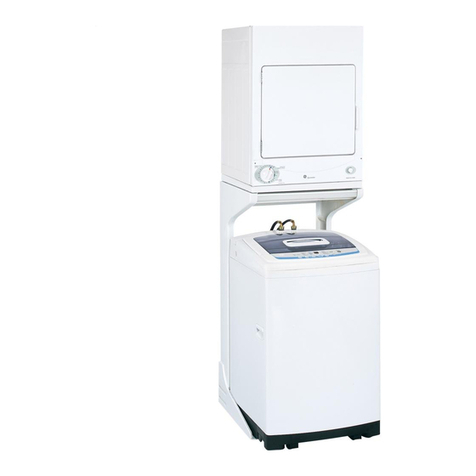
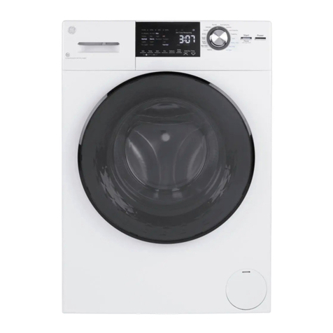
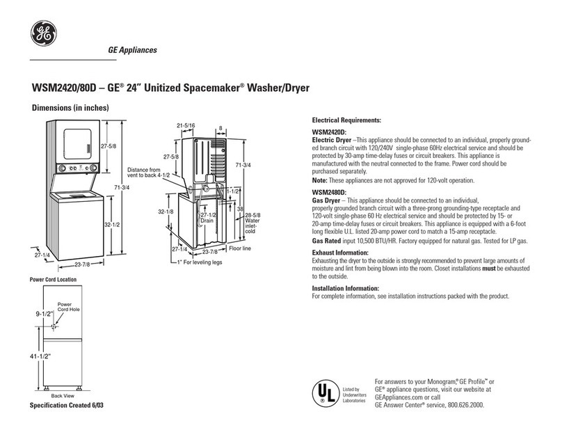
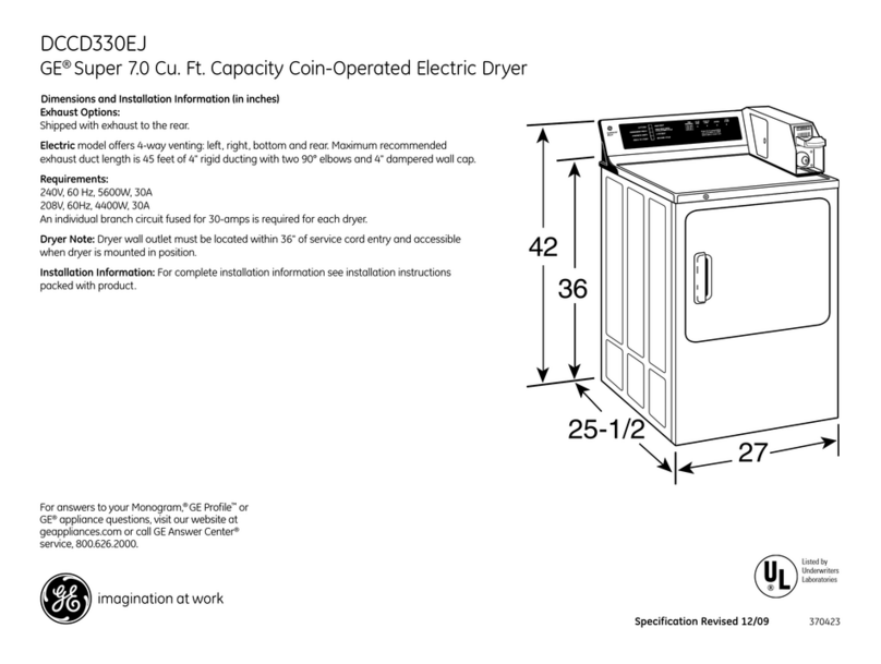
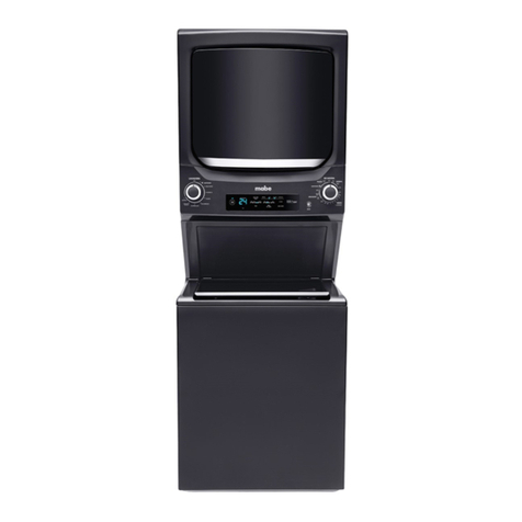
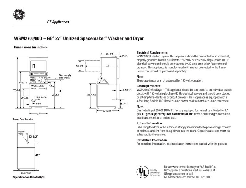
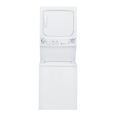
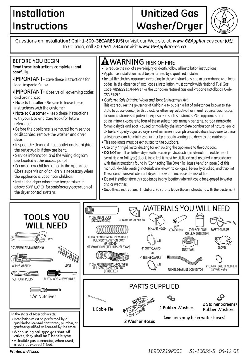
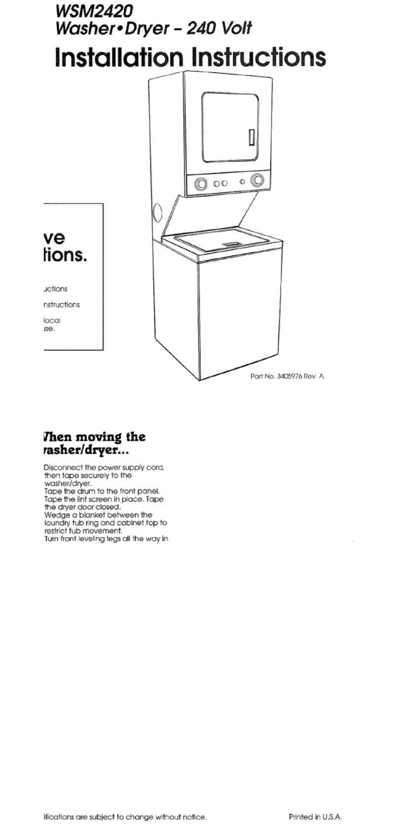
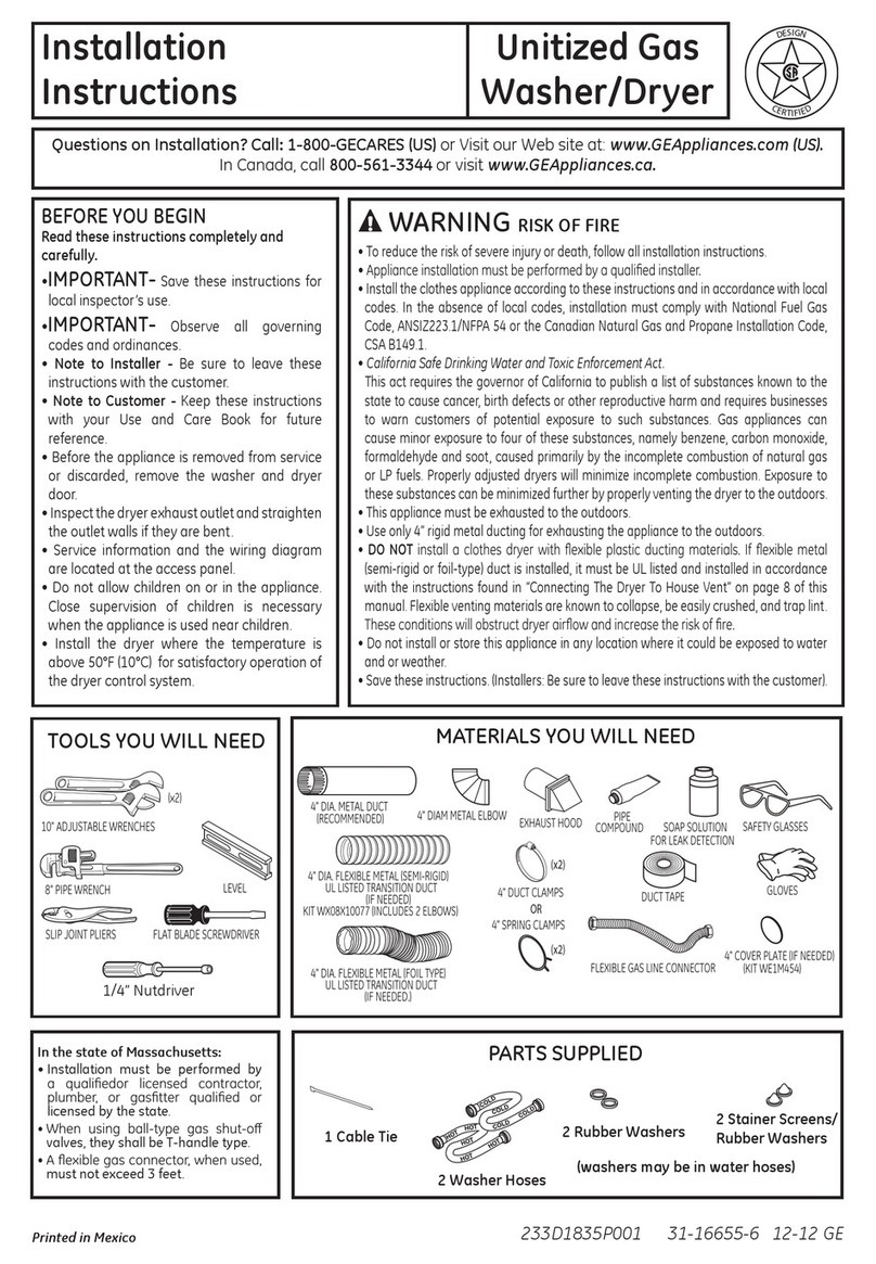
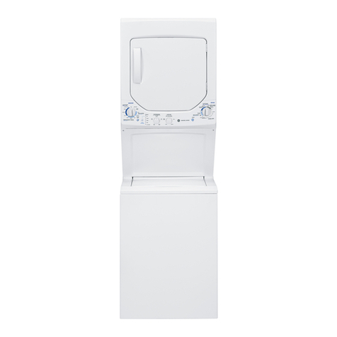
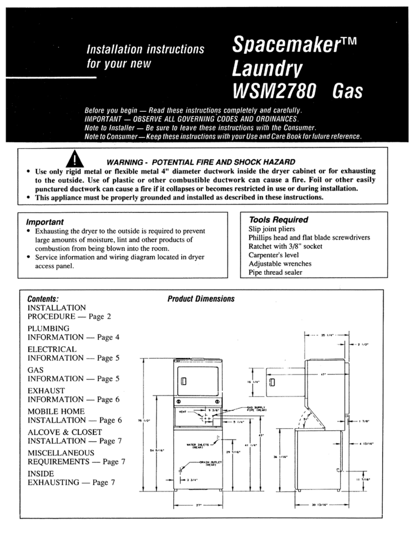
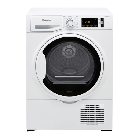
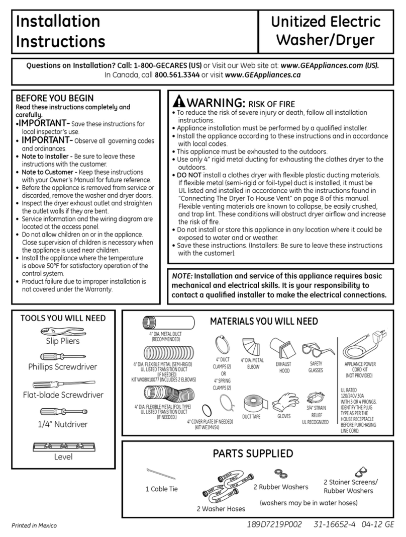
GE GTUP270EM3WW User manual

Installation
Instructions Unitized Electric
Washer/Dryer
Questions on Installation? Call: 1-800-GECARES {US}or Visit our Web site at: www.GEAppliunces.com (USJ.
In Canada, call 888-561-3344 or visit www.GEAppliunces.cu
BEFORE YOU BEGIN
Readtheseinstructionscompletelyandcarefully.
•IMPORTANT-Savetheseinstructionsfor
localinspector'suse.
•IMPORTANT-Observeoil governingcodes
and ordinances.
• Noteto Installer - Besureto leavethese
instructionswith thecustomer.
Noteto Customer - Keeptheseinstructions
with your Useand CoreBookfor future
reference.
Beforethe applianceisremovedfrom service
or discorded,removethewasher anddryer
doors.
Inspectthe dryerexhaustoutlet and straighten
the outletwalls ifthey ore bent.
Serviceinformationand thewiring diagram
ore locatedat theaccesspanel.
Donot allowchildrenon or in theappliance.
Closesupervisionof childrenisnecessary
whenthe applianceisusednearchildren.
tnstollthe appliancewherethe temperatureis
above50°Ffor satisfactoryoperationofthe
control system.
WARNING RBKOFFmRE
Toreduce the risk of severe injury or de(]th, follow (]11inst(]ll(]tion
instructions.
Appliance inst(]llution must be performed by (] qualified installer.
Install the (]ppliunce (]ccording to these instructions (]nd in (]ccord(]nce
with local codes.
This (]ppliunce must be exh(]usted to the outdoors.
Use only 4" rigid met(]l ducting for exh(]usting the clothes dryer to the
outdoors.
DO NOT inst(]ll u clothes dryer with flexible plastic ducting m(]teri(]ls.
If flexible metal (semi-rigid or foil-type) duct is installed, it must be
ULlisted (]nd installed in accordance with the instructions found in
"Connecting The Dryer To House Vent" on page 8 of this m(]nuul.
Flexible venting muteri(]ls (]re known to coll(]pse, be e(]sily crushed,
(]nd tr(]p lint. These conditions will obstruct dryer (]irflow (]nd incre(]se
the risk of fire.
Do not inst(]ll or store this (]ppli(]nce in (]ny Ioc(]tion where it could be
exposed to w(]ter (]nd or we(]ther.
S(]vethese instructions. (Inst(]llers: Be sure to le(]ve these instructions
with the customer).
NOTE: Installation and service of this appliance requires basic
mechanical and electrical skills. It is your responsibility to
contact a qualified installer to make the electrical connections.
TOOLS YOU WILL NEED
Slip Pliers
Phillips Screwd river
Fiat-blade Screwd river
1/4" Nutdriver
Level
4' DIA.METALDUCT
(RECOMMENDED}
MATERIALSYOUWILLNEED
4"DUCT
4' DIA,FLEXIBLEMETAL(SEMI-RIGID} CLAMPS(2}
ULLISTEDTRANSITIONDUCT
(IFNEEDED} OR
KITWXOBXlOO77(INCLUDES2ELBOWS} 4' SPRING
CLAMPS(2}
4' DIA,FLEXIBLEMETAL(FOILTYPE}
ULLISTEDTRANSITIONDUCT k.)
(IFNEEDED.} 4' COVERPLATE(IFNEEDED}
(KITWE1M4S4}
%
4' DIA,METAL
ELBOW
DUCTTAPE
EXHAUST
HOOD
GLOVES
SAFETY
GLASSES
3/4"STRAIN
RELIEF
ULRECOGNIZED
APPLIANCEPOWER
CORDKIT
(NOTPROVIDED}
ULRATED
120/240V,30A
WITH3OR4PRONGS,
IDENTIFYTHEPLUG
TYPEASPERTHE
HOUSERECEPTACLE
BEFOREPURCHASING
LINECORD,
1 C(]ble Tie
PARTSSUPPLIED
oo
2 St(]iner Screens/
2 Rubber W(]shers RuuberW(]shers
(w(]shers m(]y be in w(]ter hoses)
2 W(]sher Hoses
189D7219PO02 31-16652-2 04-11 GE

Installation instructions
INSTALLATION REQUIREMENTS LOCATION
This appliance must be installed on firm flooring to
minimize vibration during spin cycle. Concrete flooring is
best, but wood base issumcient, provided floor support
meets FHAstandards. This appliance should not be
installed on rugs or exposed to weather.
PLUMBING
WATERPRESSURE- Must be 20 psi minimum to 120 psi
maximum.
WATERTEMPERATURE- Household water heater should be
set to deliver water at 120°to 150°F (50° to 66°C)IN THE
WASHERwhen hot wash is selected.
SHUTOFFVALVES- Both hot and cold shutoff valves
(faucets) should be supplied.
DRAIN- Water may be drained into standpipe or set tub.
Discharge height MUSTNOTBELESSTHAN30 INCHES,
and no more than 6feet above the base of the washer.
Standpipe must be 1-!/2 inches minimum inside diameter
and must be open to atmosphere.
ELECTRICAL REQUIREM ENTS
CAUTION: Before plugging in washer, read the follow-
ing electrical requirements.
CAUTION: For personal safety, do not usean
extension cord or adapter plug with this appliance. Do
not, under any circumstances, cut or remove the third
grounding prong from the power cord. Follow national
electrical codes and ordinances. This appliance must be
supplied with the voltage and frequency indicated on the
rating plate (located at the top of the dryer front panel),
and connected to an individual, properly grounded branch
circuit, protected by a 30-amp circuit breaker or
time-delay fuse. If the electric supply provided does not
meet the above requirements, call a licensed electrician.
Step 1 Prepare the Area and Exhaust for Installation of
Appliance (seesection 1).
Step 2 Check and Ensure the Existing External Exhaust is
Clean (seesection 1)and Meets Attached Installation
Specifications (seesection 3).
Step:3Removethe Foam Shipping Pads (seesection 1).
Stepz_Move the Appliance to the Desired Location.
Step 5 Connect the Power Supply (see section 2).
Step 6 Connect the External Exhaust (seesection/4).
Step 7 LevelYour Appliance (seesection 5).
Step8 Connect to plumbing facilities (seesection 8).
Step 9Check the Operation of the Power Supply
and Venting.
Step 10 Placethe Owners Manual and the Installation
Instructions in a Location Where They Will Be Noticed By
the Owner.
ForAlcove or Closet Installation, see section 10.
For Bathroom or Bedroom Installation, see section 11.
For Mobile or Manufactured Home see, section 9.
For side or bottom exhaust, see section 6.
2

Installation Instructions
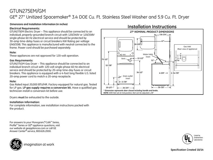
24" NOMINAL PRODUCT DIMENSIONS
.5"
51"_
!9.! "J
_._ Water inlets
I (rear)
_-- 4.1"
' Drain outlet
-W (rear)
_----- 23.75" -----_
32.7"
m
•_---------27.25"---------_
* Dimension represents door closed including handle and knobs.
NOTE:With feet set at mid position, feet can be adjusted +_.575".
27" NOMINAL PRODUCT DIMENSIONS
52.9"
27.7"
20.2" J
_ 0
O0 •
Water inlets
-_--_ (rear)
_-- 2.9"
I •
_..__.. Dram outlet
(rear)
, 3.9"
_---- 26.8"
*Dimension represents door closed including handle and knobs.
NOTE:With feet set at mid position, feet can be adjusted +_575".
3

Installation Instructions
Minimum Clearance Other Than Alcove or Closet Installation
Minimum clearance to combustible surfaces and for air opening are: 0 in. clearance both sides and 1 in. rear.
Consideration must be given to provide adequate clearance for installation and service.
[i] PREPARING FOR INSTALLATION
OF NEW APPLIANCE
REMOVING LINT FROM WALL EXHAUST
OPENING
. Remove and discard existing plastic or metal foil
transition duct and replace with UL listed transition
duct.
WALL
INTERNALDUCT CHECKTHATEXHAUST
OPENING DAMPEROPENS
ANDCLOSESFREELY.
TILTTHE APPLIANCE
SIDEWAYS AND REMOVE
THE FOAM SHIPPING PADS
BY PULLING AT THE SIDES
AND BREAKING THEM
AWAY FROM THE APPLIANCE
LEGS. BESURE TO REMOVE
ALL OF THE FOAM PIECES
AROUND THE LEGS.
After the machine isin the
home, remove remaining
packing material/carton
from washer.
DO NOT REMOVESHIPPING
RODAT THIS TIME.
Removestyrofoam block.
Removethe bag containing
the Washer hoses and
parts parts from tub. Put
styrofoam block back in tub
opening to hold tub in place
during the rest of installation.
Move washer closeto final
position. Make surethere
isat least a 24" clearance
on right side of washer to
remove shipping bar.PULL
SHIPPINGBAROUTUSING
YELLOWPLASTICHANDLE.
Keep bar so it can be
reinstalled ifwasher isever
moved again.
H
Styrofoam Block
\
Washer hoses
and parts II
Yellow plastic handle
NEW HONE OR REMODELING FAUCETS/
DRAIN STANDPIPE/ELECTRICAL LOCATION
12"--_
i
Locate spigots,
drain standpipe
and electrical plug
in this area
!
Right side of
Unitized Washer/
Dryer.
T
,, 42"
FLOOR
_ELECTRICAL CONNECTION
INFORMATION
WARNING - TO REDUCE THE
RISK OF FIRE, ELECTRICAL SHOCK AND
PERSONAL INJURY:
,, DO NOT USE AN EXTENSION CORD OR AN
ADAPTER PLUG WITH THIS APPLIANCE.
Appliance must be electrically grounded in
accordance with local codes and ordinances, or in
the absence of local codes, in accordance with the
NATIONALELECTRICALCODE,ANSI/NFPANO.70.
ELECTRICAL REQUIREMENTS
This appliance must be connected to an individual
branch circuit, protected by the required time-delay
fuses or circuit breakers. A four or three-wire, single
phase, 120/240V or 120/208V, 60Hz,30 amp circuit
is required. If the electric supply does not meet the
above specifications, then call a licensed electrician.
GROUNDING INSTRUCTIONS
A.For a grounded, cord-connected appliance:
This appliance must be grounded. In the event of mal-
function or breakdown, grounding will reduce the risk
of electric shock by providing a path of least resistance
of electric current. This appliance isequipped with a
cord having an equipment-grounding conductor and a
grounding plug. The plug must be plugged into an ap-
propriate outlet that is properly installed and grounded
in accordance with all local codes and ordinances.
WARNING -Improperconnectionofthe
equipment-groundingconductorcan resultina risk
ofelectricshock.Check witha qualifiedelectrician
orservicemanifyou areindoubt astowhetherthe
applianceisproperlygrounded.
4

Installation
GROUNDING INSTRUCTIONS {Cont.}
Do not modify the plug provided with the appliance. If it
will not fit the outlet, have a proper outlet installed by a
qualified electrician.
B.For permanently connected appliance:
This appliance must be connected to a grounded,
metal, permanent wiring system, or an equipment-
grounding conductor must be run with the circuit
conductors and connected to the equipment ground-
ing terminal or lead on the appliance.
CONNECTING APPLIANCE USING 4-WIRE
CONNECTION {MUST BE USED FOR
MOBILE HOME INSTALLATION}
NOTES:Slnce January 1,1996, the National Electric code
requires that the new constructions utilize a4-wire
connection to an electric dryer.
WARNING:only o4-conductorcordshall
be usedwhen theapplianceisinstalledina location
where groundingthroughthe neutralconductoris
prohibited.Groundingthroughthe neutralisprohibited
forthenew branch-circuitinstallations,mobilehomes,
recreationalvehicles,and areaswhere localcodes
prohibitgroundingthroughtheneutralconduction.
REMOVEGROUNDSTRAP
ANDD)SCARDKEEPGREEN
GROUNDSCREW ['8-/ WIRE RELOCATEGREEN
GROUNDSCREW
-'_ _/_b HERE GREENOR
RELIEF
BRACKET
COVER
HOT
WIRE 3/4",UL /_
RECOGNIZED
STRAINRELIEF
R#10AWGNINI'_IUNCOPPER
CONDUCTORSOR120/2z_OV30APOWER
SUPPLYCORDKITMARKEDFORUSE
WITHDRYERS&PROVIDEDWITH
CLOSEDLOOPORSPADETERMINALS
WITHUPTURNEDENDS(NOTSUPPLIED)
1.Turn off the circuit breaker (s)(30 amp) or remove the
dryer's circuit fuse at the electrical box.
2. Be sure the appliance cord is unplugged from the wall
receptacle.
3. Remove the power cord cover located at the lower
back.
4. Remove and discard ground strap. Keep the green
ground screw for step 7.
5. Install 3/4 in. ULrecognized strain relief to power cord
entry hole. Bring power cord through strain relief.
6. Connect power cord as follows:
A. Connect the 2 hot linesto the outer screws of
the terminal block (marked L1 and L2).
B.Connect the neutral (white)line to the center of
the terminal block (marked N).
7.Attach ground wire of power cord with the green
ground screw (hole above strain relief bracket). Tighten all
terminal block screws (3)completely.
Instructions
8. Properly secure power cord to strain relief.
9. Reinstall the cover.
WARNING: NEVER LEAVE THE
COVER OFF OF THE TERMINAL BLOCK.
CONNECTING DRYER USING 3-WIRE
CONNECTION
GREEN GROUND
GROUND STRAP
SCREW HOT
WIRE STRAINRELIEF
BRACKET
3/4"',UL
RECOGNIZED
RELIEF
NEUTRAL
(White) HOT
WIRE
] #i0 AWGMINIMUMCOPPER
COVER CONDUCTORSORi20/240V]0A POWER
SUPPLYCORDKITMARKEDFORUSE
WITHDRYERS&PROVIDEDWITHCLOSED
LOOPORSPADETERMINALSWITH
UPTURNEDENDS(NOTSUPPLIED/,
1.Turn off the circuit breaker(s) (:30amp) or remove the
dryer's
circuit fuse at the electrical box.
2. Be sure the dryer cord is unplugged from the wall.
3. Remove the power cord cover located at the lower
back.
/4.Install 3/4 in. ULrecognized strain relief to power cord
entry hole. Bring power cord through strain relief.
5. Connect power cord asfollows:
A.Connect the 2 hot lines to the outer screws of
the terminal block (marked L1and L2).
B.Connect the neutral (white) line to the center of
the terminal block (marked N).
6. Be sure ground strap is connected to neutral (center)
terminal of block and to green ground screw on cabinet
rear.Tighten all terminal block screws (3)completely.
7. Properly secure power cord to strain relief.
8. Reinstall the cover.
_ELW_K|_||_O: NEVER LEAVE THE
COVER OFF OF THE TERMINAL BLOCK.
5

Installation instructions
[] EXHAUST INFORMATION
WARNING -IN CANADA AND IN
THE UNITED STATES, THE REQUIRED EX-
HAUST DUCT DIAMETER IS 4 IN (102ram). DO
NOT USE DUCT LONGER THAN SPECIFIED IN
THE EXHAUST LENGTH TABLE.
Using exhaust longer than specified length will:
, Increase the drying times and the energy cost.
, Reduce the dryer life.
, Accumulate lint, creating a potential fire hazard.
The correct exhaust installation is YOUR
RESPONSIBILITY.Problems due to incorrect
installation (]re not covered by the warranty.
Remove and discard existing plastic or metal foil
transition duct and replace with ULlisted transition
duct.
The MAXIMUM ALLOWABLEduct length and number
of bends of the exhaust system depends upon the
type of duct, number of turns, the type of exhaust
hood (wall cap), and all conditions noted below. The
maximum duct length for rigid metal duct isshown in
the table below.
27" DRYER EXHAUST LENGTH
RECOMMENDEDMAXIMUMLENGTH
Exhaust Hood Tgpes
Recommended Use onlg for short
run installations
4" DIA
No, of 90 ° Rigid Rigid
Elbows Metal Metal
0 56 Feet 42 Feet
1 46 Feet 36 Feet
2 34 Feet 28 Feet
3 32 Feet 18 Feet
24" DRYEREXHAUST LENGTH
RECOMMENDEDMAXIMUMLENGTH
Exhaust Hood Tgpes
Use onlg for short
run installations
4" DJA
21/2"
Recommended
Rigid.
Metal
/43 Feet
33 Feet
2/4 Feet
No, of 90° Rigid
Elbows Metal
0 36 Feet
1 26 Feet
2 26 Feet
EXHAUST INFORMATION (cant}
EXHAUST SYSTEM CHECK LIST
HOOD ORWALL CAP
. Terminate in a manner to prevent back drafts or entry
of birds or other wildlife.
, Termination should present minimal resistance to
the exhaust air flow and should require little or no
maintenance to prevent clogging.
,Never install a screen in or over the exhaust duct. This
could cause lint build up.
, Wall caps must be installed at least 12 in. above ground
level or any other obstruction with the opening pointed
down.
SEPARATIONOFTURNS
Forbest performance, separate all turns by at least 4 ft.
of straight duct, including distance between last turn and
exhaust hood.
TURNSOTHERTHAN 90°
, One turn of 450 or less may be ignored.
, Two 450turns should be treated as one 900turn.
, Eachturn over 450 should be treated as one 900 turn.
SEALINGOFJOINTS
, Alljoints should be tight to avoid leaks. The male end of
each section of duct must point away from the dryer.
, Donot assemble the ductwork with fasteners that
extend into the duct. They will serve as a collection
point for lint.
, Ductjoints can be made air and moisture-tight by
wrapping the overlapped joints with duct tape.
, Horizontal runs should slope down toward the outdoors
1/2inch per foot
INSULATION
Duct work that runs through an unheated area or is
near air conditioning should be insulated to reduce
condensation and lint build-up.
6

Installation instructions
F-4-]EXHAUST CONNECTION
iLWARNING - TO REDUCE THE
RISK OF FIRE OR PERSONAL INJURY:
, This appliance must be exhausted to the outdoors.
Use only 4" rigid metal ducting for the home exhaust
duct.
Use only 4" rigid metal or UL-listed flexible metal
(semi-rigid or foil-type) duct to connect the dryer
to the home exhaust duct. It must be installed
in accordance with the instructions found in
"Connecting The Dryer To House Vent" on page 8 of
this manual.
Do not terminate exhaust in a chimney, a wall,
a ceiling, gas vent, crawl space, attic, under an
enclosed floor, or in any other concealed space of
a building. The accumulated lint could create a fire
hazard.
Never terminate the exhaust into a common duct
with a kitchen exhaust system. A combination of =
grease and lint creates a potential fire hazard.
Do not use duct longer than specified in the exhaust
length table. Longer ducts can accumulate lint,
creating a potential fire hazard.
Never install a screen in or over the exhaust duct. This
will cause lint to accumulate, creating a potential fire
hazard.
Do not assemble ductwork with any fasteners
that extend into the duct. These fasteners can
accumulate lint, creating a potential fire hazard.
Do not obstruct incoming or exhausted air.
Provide an access for inspection and cleaning of
the exhaust system, especially at turns and joints.
Exhaust system shall be inspected and cleaned at
least once a year.
THIS DRYER COMES READY FOR REAR
EXHAUSTING. IF SPACE IS LIMITED, USE
THE INSTRUCTIONS IN SECTION 6 TO
EXHAUST DIRECTLY FROM THE SIDES
OR BOTTOM OF THE CABINET.
STANDARD REAR EXHAUST
Forstraight lineinstallation,connect
the drger exhaustto the external
exhausthood usingduct tapeor
clamp.EXTERNALDUCT
OPENING
DUCTTAPE OR
DUCT CLAIVlp
4" IVlETALDUCT CUT
TO PROPERLENGTH
DUCTTAPEOR
DUCT CLAIVlp
STANDARD REAR EXHAUST
(Vented above floor level}
L
AGE
NOTE: ELBOWS WILL PREVENT DUCT KINKING AND COLLAPSING
ELBOW HIGHLY
RECOMMENDED
[_]LEVELING AND STABILIZING YOUR
APPLIANCE
/ /
_E LEVEL
-T0-SIDE
FRONT-T0-BACK,
_Z_
2LEVELINGLEGS
Level and stabilizing your appliance
1.Carefully move the appliance to its final location.
Gently rock the appliance into position. It is important
not to damage the rubber leveling legs when mov-
ing your appliance to its final location. Damage legs
can increase appliance vibration. It may be helpful to
spray window cleaner on the floor to help move your
appliance to its final position.
Note: do not use washer cover to lift the unit.
2.To ensure the appliance is level and solid on all four
legs,tilt the appliance forward so the rear legs are off
the ground. Gently set the appliance back down to
allow the rear legs to self adjust.
]. With the appliance in its final position, place a level on
top of back part of the washer lid and check it side to
side, then check front to back. Screw the front leveling
legs up or down to ensure the appliance is resting solid
on all four legs (no rocking or the appliance should ex-
ist),turn the lock nuts on each leg up toward the base
of the unit and snug with a wrench.
Note: Keep the leg extension at minimum to prevent
excessivevibration. Thefarther out legs are extended, the
more the unit will vibrate.
7
Installation
CONNECTING THE DRYERTO HOUSEVENT
RIGIDMETALTRANSITIONDUCT
• Forbest dryingperformance,a rigid metaltransition duct is
recommended.
• Rigidmetaltransitionsducts reducethe riskof crushingand
kinking.
UL-LISTEDFLEXIBLEMETAL(SEMI-RIGID)TRANSITIONDUCT
• tf rigid metalduct cannot be used,then UL-listedflexible metal
(semi-rigid)ducting can beused(KitWX08X10077).
• Neverinstallflexible metalduct inwalls,ceilings,floors or
otherenclosedspaces.
• Total lengthofflexiblemetal duct shouldnot exceed8 feet
(2.4m).
• Formany applications,installingelbowsat boththe dryerand
the wall ishighlyrecommended(seeillustrations).Elbows
allowthe applianceto sit closeto the wallwithout kinking
andor crushingthetransition duct,maximizingdrying
performance.
• Avoidrestingthe duct on sharpobjects.
UL-LISTEDFLEXIBLEMETAL(FOIL-TYPE}TRANSITIONDUCT
•tnspecialinstallations,it may be necessaryto connectthe
dryerto the housevent usinga flexiblemetal (foil-type)duct.
A UL-listedflexiblemetal (foil-type)ductmay beusedONLY
in installationswhererigid metalor flexiblemetal (semi-rigid)
ductingcannot be usedANDwherea4" diameter can be
maintainedthroughout theentirelengthof thetransition
duct.
• tnCanadaandthe UnitedStates,onlythe flexiblemetal(foil-
type)ductsthat complywith the"Outlinefor ClothesDryer
TransitionDuctSubject2158A"shallbe used.
• Neverinstallflexible metalduct inwalls,ceilings,floors or
otherenclosedspaces.
• Total lengthofflexiblemetal duct shouldnot exceed8 feet
(2.4m).
• Avoidrestingthe duct on sharpobjects.
• Forbest dryingperformance:
1.Slideoneend ofthe duct overtheclothesdryeroutlet pipe.
2.Securetheduct with a clamp.
3.With thedryer in itspermanentposition,extendthe duct to
itsfull length.Allow2" ofduct to overlaptheexhaustpipe.
Cut off and removeexcessduct. Keepthe duct as straight
as possiblefor maximum airflow.
4.Securetheduct to the exhaustpipewith theother clamp.
nstructions
DO
ELBOW HIGHLY
RECOHHENDED
DO NOT USE
EXCESSIVE
EXHAUST
LENGTH
DON'T
!IIAPPLIANCE
I IIONFLEXIBLE
_EXHAU_
.....,d
8

Installation Instructions
E_ 24" MODELS ONLY:
DRYER EXHAUST TO RIGHT, LEFT
OR BOTTOM CABINET
, WARNING - BEFOREPERFORMING
THIS EXHAUST INSTALLATION, BESURE
TO DISCONNECT THE APPLIANCE FROM
ITS ELECTRICAL SUPPLY. PROTECT YOUR
HANDS AND ARMS FROM SHARP EDGES
WHEN WORKING INSIDE THE CABINET.
BE SURE TO WEAR GLOVES
For downward venting, rotate elbow
sections so that elbow points downward
REMOVE
KNOCKOUT
(ONLY 1)
0
ADDING ELBOW AND DUCT FOR
EXHAUST TO LEFT OR RIGHT SIDE OF
CABINET
. Rotate elbow sections so that the opening points to the
side to which you want to vent. Preassemble 4" elbow
with 4" duct. Use only 4" ULapproved rigid metal for
ducting inside the dryer.
. Connect duct assembly to the internal elbow.
CAUTION: Be sure not to pull or damage the
electrical wires inside the dryer when inserting the duct.
4" ULapproved rigid metal
DUCT
9
. Apply duct tape as shown on the joint between the dryer
internal duct and the straight duct pipe.
, CAUTION:
Internal duct joints must be
_ ecured with tape, otherwise
they may separate and cause
a safety hazard.
27" MODELS ONLY:
DRYER EXHAUST TO RIGHT, LEFT OR
BOTTOM CABINET
, WARNING - BEFOREPERFORMING
THIS EXHAUSTINSTALLATION, BESURE
TO DISCONNECTTHE APPLIANCE FROM
ITS ELECTRICAL SUPPLY. PROTECT YOUR
HANDS AND ARMS FROM SHARPEDGES
WHEN WORKING INSIDE THE CABINET. BE
SURE TO WEAR GLOVES.
For downward venting, rotate elbow
sections so that elbow points downward
EXHAUST TO LEFT OR RIGHT SIDE OF
CABINET
. Rotate elbow sections so that the opening points to the
side to which you want to vent. Preassemble 4" elbow
with 4" duct. Useonly 4" ULapproved rigid metal for
ducting inside the dryer.
. Connect duct assembly to the internal elbow.
CAUTION: Be sure not to pull or damage the
electrical wires inside the dryer when inserting the duct.
i]r!
. Apply duct tape as shown on the joint between the dryer
internal duct and the straight duct pipe.
CAUTION:
H nternal duct joints must besecured with tape, otherwise
they moy separate and cause
a safety hazard.

Installation
I- PLUMBING INFORMATION
WATER SUPPLY REQUIREMENTS
, HOTAND COLDWATERFAUCETS- Must be within 42" of
the appliance water inlet hose connections. The faucets
must be 3/4" garden hose-type so inlet hoses can be
connected.
,WATERPRESSURE- Must be between !0 and 120
pounds per square inch with a maximum unbalance
pressure, hot vs. cold flowing, of !0 pounds per square
inch.
,WATERTEMPERATURE- Water heater should be set to
deliver 140°to !50°F (60°to 66°C)in the washer when
HOTwash isselected.
, SHUT-OFFVALVES- Both hot and cold water shut-off
valves (faucets) should be supplied.
, LOCATION- Do not install appliance in an area where
the temperature will fall below freezing. If appliance
isstored or transported in freezing temperatures, be
sure all water from the fill and drain systems has been
removed.
DRAIN REQUIREMENTS
, DRAINRATE- The drain or standpipe must be capable
of accepting a discharge at the rate of 16 gallons per
minute.
, DRAINHEIGHT- The drain height must be 33" minimum
and 96" maximum.
, STANDPIPEDIAMETER- The standpipe diameter must
be 1-1/2" minimum. There MUSTbe an air gap around
the drain hose in the standpipe. A snug fit can cause a
siphoning action.
, SIPHONBREAKKIT- Fora drain facility less than 33"
high, the hose, coupling and clamps provided in the
machine must be used and, in addition, a siphon break
MUSTbe installed on the back of the machine. Use
Siphon Break KitWH49X228 and follow instructions in
the kit.
Instructions
18-1CONNECTING TO PLUMBING
FACILITI ES
c
H
If not installed, install rubber washer in one end of hot water
hose.Thread hot water hose onto connection labeled Hat
top rear of washer. Handtighten, plusan additional 1/8 turn
with pliers.
If not installed, install rubber washer in one end of cold water
hose.Thread cold water hose onto connection labeled Cat
top rear of washer. Handtighten, plusan additional 1/8 turn
with pliers.
Moveappliance as close to final location as possible,leaving
room for you to make water, drain, electrical and vent
connections to your home.
NOTE:Iflonger drain hose is
required,order drain hose
extension kit, GEpart number
WH49X301.Connectadditional
drain hose (contained in kit)to
original hosewith hoseclamp
(contained in kit).
Insertfree end of drain hose
into drain opening ofyour
home up to drain hosestopper
(do not remove hosestopper
it preventssiphoning).If water
valvesand drain are built into
wall, fasten drain hoseto one
of water hoseswith cable tie
provided(ribbed sideon inside).
Ifyour drains isa standpipe,
fasten drain hoseto standpipe
with cabletie provided.
10

Installation instructions
[-97MOBILE OR MANUFACTURED HOME
INSTALLATION
. Installation MUST conform to the MANUFACTURED
HOME CONSTRUCTION &,SAFETY STANDARD,
TITLE24,PART 32-80or,when suchstandardisnot
applicable,withAMERICAN NATIONAL STANDARD FOR
MOBILE HOME, ANSI/NFPA NO. 501B.
. The appliance MUSTbe vented to the outdoors with
the termination securely fastened to the mobile home
structure.
. The vent MUSTNOT be terminated beneath a mobile or
manufactured home.
. The vent duct material MUSTBEMETAL.
. Do not use sheet metal screws or other fastening
devices which extend into the interior of the exhaust
vent.
. See section 2 for electrical connection information.
[_ ALCOVE OR CLOSET INSTALLATION
. If your appliance is approved for installation in an
alcove or closet, it will be stated on a label on the
appliance back.
TO PREVENTLARGEAMOUNTSOFLINTAND MOISTURE
FROMACCUMULATINGAND TOMAINTAINDRYING
EFFICIENCY,THISMACHINEMUSTBEEXHAUSTED
OUTDOORS.
Do not install this appliance with lessthan the minimum
clearances shown above.
CONSIDERATION MUST BE GIVEN TO PROVIDE
ADEQUATE CLEARANCES FOR INSTALLATION
AND SERVICE.
ACAUTION: DONOTINSTALLTHIS
APPLIANCEIN A CLOSETWITH A SOLID DOOR.
DOOR VENTILATION OPENING {27"
MODELS)
A minimum of 120 square inches of opening, equally
divided at top and bottom, is required. Air openings are
required to be unobstructed when a door is installed.
A Iouvered door with equivalent air openings for the
full length of the door isacceptable.
27" Model
"111 :17
/' /
jlo ,!
'JJ;0sq,n
When louvers or registers are placed in door openings, the
free air openings of the louvers or registers must equal 120
square inches.
DOOR VENTILATION OPENING (24"
MODELS)
A minimum of 72 square inches of opening is required. Air
openings are required to be unobstructed when a door is
installed. A Iouvered door with equivalent air openings for
the full length of the door isacceptable.
24" Model i°
When louvers or registers are placed in door openings, the
free air openings of the louvers or registers must equal 72
square inches.
ih7BATHROOM OR BEDROOM iNSTALLATiON
. The appliance MUSTbe vented to the outdoors. See
E×HAUSTINFORMATIONsection 3 & 4.
The installation must conform with local codes or, in the
absence of local codes, with the NATIONAL ELECTRICAL
CODE,ANSI/NFPA NO. 70.
11

Installation instructions
[] SERVICING
h.
,_WARNING- LABEL ALL WIRES PRIOR TO DISCONNECTION WHEN SERVICING
CONTROLS. WIRING ERRORS CAN CAUSE IMPROPER AND DANGEROUS OPERATION
AFTER SERVICING/INSTALLATION.
Forreplacement parts and other information, refer to
Owner's ivlc]nuc]lfor servicing phone numbers.
TO REGISTER YOUR DRYER
CALL TOLL-FREE
1-888-269-1192
In Canada call 888-561-3344
Prompt registration confirms your right to protection
under the terms of your warranty.
www.GEAppliances.com (US)
www.GEAppliances.ca (Canada)
For Questions on Installation, Coil: !-800-GECARES (US)
12

Instructions Laveuse/S6cheuse
D'Installation ElectriquesUnitiZes
I Question sur I'instalJation?AppeJez au 888.561.3344 {Canada)
Ou visiteznotre siteweb" www.electromenagersge.ca
AVANT DECOMMENCER
LisezJesinstructions compl@tementet avec
attention.
•IM PORTANT- Gardezcesinstructionspour
uneutilisationpossiblepar un r@arateur local.
•IMPORTANT- Respectezlesnormesen
vigueuret ordonnances.
• Note pour I'instatlateur - Assurez-vousde
laissercesinstructionsavec leclient.
•Notepour leclient- Gardezcesinstructions
avecvotre manueld'utilisationet d'entretien
pour uneconsultationfuture possible.
•Avant queI'appareilsoitd6plac6apres
r@aration ou pour@trejet6,enlevezlesportes
dela laveuseet de las6cheuse.
•Contr61ezlessortiesd'6chappementetredressez
I'installationsurlemur sielleesttordue.
• Lesinformationsde r@arationet lediagramme
desconduitssont situ@ssurletableaud'acces.
• Emp@chezlesenfantsd'@tresurou dans
I'appareil.Unesupervisionprochedesenfants
estn@cessaireIorsqueI'appareilestutilis&
• tnstallezI'appareiloOla temp@atureest
en-dessousde 50°Fpour unfonctionnement
satisfaisantdu systemede contr61e.
A ATTENTION RIESOUED'INCENDIE
•Pourr@duirelesrisquesdeblessuresgravesoudemort,suivezJesinstructions
d'instaltation.
•L'instattationdeI'appareitdolt@trefaiteparunepersonnequalifi6e.
•InstaltezI'appareilsetoncesinstructionsetconform@mentauxnormeslocales.
•Cettes@cheusedoltavoirunsystemed'@happementversl'ext@rieur.
•Utilisezseulementdesconduitsrigidesenm_talde4" pourla canalisationdela
s_cheuseversl'ext_rieur.
•NEPASinstallerunes6cheuseavecdesconduitsflexibtesenptastique.Siles
conduitsflexibtesdem@tal(semi-rigideouenaluminium)sontinstall@s,ilsdoivent
@treULetinstatt@sconform@mentauxinstructionstrouv@esdans
<<BranchezLaS@heuseAuxConduitsdetaMaison>>dela page8decemanuel.
Lesmat@riauxdesconduitsflexiblessontconnuspoursefendre,s'@cras@set@tre
despiegesa petuches.Cesconditionsferontobstacleaufluxd'airdelas@cheuseet
augmenterontJesrisquesd'incendie.
•N'instalJezpasetn'entreposezpascetappareitdansunendroitoOilpourrait@tre
expos@a t'eauouau dimat.
•Gardezlesinstructions.(l'instaltateurdolts'assurerdelaissercesinstructionschezte
client).
NOTE: L'installation et la r6paration de cet appareil exigent des
connaissances basics en m6canique et en 6lectrique. C'est votre
responsabifit6 de contacter un installateur quafifi6 pour faire les
connexions 6lectriques
OUTILS A UTILISER
Pince
Tourne-vis Croix
Tourne-visPlat
Tourne-vis A Douille 1A"
Niveau
)
TUYAUEN METAL
DEDIAM 4"
(RECOMMENDE)
TUYAUFLEXIBLEENMETAL
(SEMI RIGIDE)UL DEDIAM
4" (SINECESSAIRE)KIT
WXO8XlO077 (2 COUDES
INCLUS)
MATERIAL NECESSAIRE
55
COUDE DEMETAL
2 PINCESDETUYAU DEDIAM 4"
4"OU2PINCES
TENDEUR4"
ROULEAUADHESIF
POURTUYAU
CAPUCHON
D'ECHAPPEMENT
3/4" REDUCTEUR
(_ GANTS DETENSION(UL RECONNUE)
TUYAU FLEXIBLEEN METAL
(SEMIRIGIDE)UL DE DIAM 4" CACHE DE _"._"_
(SINECESSAIRE) PROTECTION(SI LUNETTES-"_'J
NECESSAIRE)DE4" DESECURITE
(KITWEIM454)
CORDON ELECTRIOUE
D'ALtMENTATION (NON
INCLUT)CONVERSION UL
120/240V, 30° AVEC 3
OU 4 DENTS. IDENTIFIEZ
LETYPE DE PRISE TEL
QUE LE RECEPTACLE
DE LA MAtSON L'EXIGE
AVANT D'ACHETER LES
FILS ELECTRIQUES.
PIECES FOURNISES
__ 2 Rondellesen Rondelles en
1 collier en _,,,/_,,,4<j_ Caoutchouc caoutchouc
plastique '_,_(______-,-_ (les joints peuvent entre
2 tuyaux de dans les tuyaux a eau)
la laveuse
189D7219PO02 31-16652-2 04-11 GE

Instructions d'Installation
CONDITIONS D'INSTALLATION
DEUEMPLACEMENT
Cet appareil doit 6tre install6 surun sol solide pour
minimiser les vibrations durant le cycle d'essorage. Le sol
en b6ton est meilleur, mais une base en bois est sumsante.
Cet appareil ne devrait pas 6tre install6 sur untapis ou
e×pos6 au climat.
PLOMBERIE
PRESSIONDEUEAU- Elledolt 6tre de 20 psi minimum et
120 psi maximum.
TEMPERATUREDEL'EAU- le chauffe-eau de votre maison
dolt 6tre configur6 pour distribuer une eau de 120o 6 150°F
150° 6 66oC) BANSLA LAVEUSEIorsque I'eau chaude est
s61ectionn6e.
VALVESDEFERMETURE- La valve de fermeture d'eau
froide et celle d'eau chaude (robinet) doivent _tre fournies.
DRAINAGE- L'eau peut _tre drain_e par le tuyau de
rejet 6 I'_gout ou par le bac configur6. La hauteur de
1'6coulement.
NEDOlTPASETREINFERIEUREA 30 POUCES,et pas plus
de 6 pieds audessus de la base de la laveuse. Letuyau
de reject (31'6goutdoit mesurer 1-!/2 pouce minimum (3
I'int@ieur du diam_tre et doit _tre ouverte vers I'ext@ieur.
CONDITIONS ELECTRIQUES
PRUDENCE: Avant de brancher la laveuse, lisez les
conditions electriques suivantes.
PRUDENCE: Pourvotre propre s_curit6, n'utilisez
pas de rallonge ou d'adaptateur avec cet appareil.
Necoupez pas ni enlevez la troisi_me dent de la prise
61ectriquecorrespondant (3la masse. Suivez lesnormes
61ectriquesnationales pour le voltage et la fr6quence
indiqu6s sur la plaque de conversion (situ_e au-dessus
de la s6cheuse sur le tableau avant), et branchez (3une
prise individuelle,correctement connect6e (3la terre,
prot6g_e par disjoncteur de 30-amp ou un fusible (3
retardement.Si I'installation 61ectrique ne r6pond pas aux
conditions ci-dessus, appelez un 61ectricienqualifi6.
Etape ! Pr6parez la Zone et I'Echappement de Etape 9 V@ifiez le Fonctionnement du Courant Electrique
Etape
Etape
Etape
Etape
Etape
Etape
I'installation de I'Appareil (voir section 1).
Etape 2 V@ifiez et Assurez I'Echappement Existant Externe
qu'il soit Propre (voirsection 1)et lesSp6cifications
d'lnstallation Ci-jointes (voirsection 3).
3 Enlevezla Mousse de Rembourrage de Transport
(voir section 1).
4 D6placez I'appareil au Lieu D6sir_.
5 Branchez I'appareil au Courant Electrique (voir
section 2).
6 Branchez I'Echappement Externe (voir section/4).
7 Nivelez I'appareil (voir section 5).
8 Raccordez au syst_me de plomberie (voirsection 8)
et la Ventilation.
Etape 10 Placez le Manuel de I'Utilisateur et les
Instructions d'lnstallation dans un Lieu O_ IIs
Seront Trouv6s Par le Propri@aire.
Pour le Renfoncement ou I'lnstallation dans un iVleuble,
voir section 10.
Pour I'installation dans une salle de bain ou une
chambre, voir section 11.
Pour I'installation dans un mobile home, voir section 9.
Pour 1'6chappement de cot6 ou artiste, voir section 6.
2

Instructions d'Installation
DIMENSIONS NOMINALES DU PRODUIT 24"
.5"
1. F:
26"
!9.r ,l
j
oioo • 0
Ventilation _--
_e
Entrees I'eau
-_ (Arri@e)
_-- 4.r'
, Sortie de
-._ vidange
,' (Arri@e)
[_-- 4.2"
I
_-J-- 23.75" J-----_
* Dimensions Iorsque les portes sont ferm#es incluant les poign#es et les boutons
NOTE•Dimensions en pieds, correspondant 6 _+375".
DIMENSIONS NOMINALES DU PRODUIT DE 27"
52.9"yc
27.7"
20.2" S
O__zoioo • 0
Entrees I'eau
-T .... (Arri@e)
J._--2.9"
, Sortie de
_.' .... vidange
_ Arri@re
_ 3.9"
J
_------ 26.8"
51°
4.35"
_---------- 30.85" --------_
* Dimensions Iorsque les portes sont ferm#es incluant les poign#es et les boutons
NOTE"Dimensions en pieds, correspondant 6 _+375".
3

Instructions d'Installation
Espace Minimum Autre Que le Renfoncement ou I'installation Dans un Meuble
L'espace minimum pour les surfaces combustibles et I'ouverture d'air sont 0 in.d'espace de chaque cot# et ! in.6 I'arri_re.
Lesconsid#rations doivent 6tre donn#es pour fournir un espace ad#quat pour I'installation et la r#paration.
[i] SE PREPARER POUR L'INSTALLATION NOUVELLEMAISON ETROBINETSREMODELES
D'U N NOUVEL APPAREIL /LETUYAUDEVIDANGEA L'EGOUT/
ENLEVER LES PELUCHES DE
L'OUVERTURE D'ECHAPPEMENT DU MUR
• Enlevez et d@barrassez-vousdesfeuilles de m@taletde
plastique du tuyau de transition et remplacez-le avec
un tuyau de transition UL.
HUR
VERIFIEZQUE LA CLE
/ D'ECHAPPEHENT
OUVREETFERHE
LIBREMENT
PENCHER L'UNITE VERS
LE COTE ET ENLEVER LES
PROTECTIONS DE TRANSPORT
DE STYROMOUSSE EN LES
BRISANT VERS L'EXTERIEUR
DES PATTESDE L'UNITE.
S'ASSURER D'ENLEVER
TOUS LES MORCEAUX DE
STYROMOUSSE AUTOURS DES
PATTES.
OUVERTURE
INTERNEDU
TUYAU
Barrede
transport Poign_ejaune
en plastique
Blocdemousse
Apr@squalamachinesoitdansvotre depolvstvr@ne_
maison,enlevezlesmat@iauxrestantset
cartonsdelalaveuse.
N'ENLEVEZ PASLESBARRESDE
TRANSPORTPOUR LE MOMENT.
En'evez'eb'°cdem°ussedeP°'ystyr_ne;U#cat_Xndet_ _}
EnlevezlesaccontenantlesTuyauxde
jonction etlespi_ces dubac.Mettezle pi_ces II
blocdemoussedepolystyrenedans II
I'ouverture du bac pour tenir le bac en
placedurantlerestedeI'instailation.
D_placezlalaveuseverslaposition
finale.Assurez-vousqu'ilyairaumoins
24"d'espace6 droitedelalaveusepour
enleverlesbarresdetransport.
TIREZ LESBARRESDETRANSPORT
VERSL'EXTERIEUR UTILISANT LA
POIGNEE JAUNE ENPLASTQUE.
Gardezlesbarresau caso0vous
devriezlar@install@ousilalaveusest
d@plac@eplustarcl.
EMPLACEMENTELECTRIQUE Cot# droit de
la Laveuse /
S#cheuse Unifi#es
<-12"---_
Localisez le robinet, la | a2"
colonne d'alimentation _"
du drainage et la prise
#lectrique de cette zone
!sol
2--1INFORMATION SUR LE BRANCHEMENT
ELECTRIQUE
I ATTENTION - POURREDUIRE
LES RISQUES D'INCENDIE, DE
DECHARGE ELECTRIQUE ET DE
BLESSURE PERSONNELLE :
, N'UTILISEZPASDERALONGEELECTRIQUEOU
D'ADAPTATEURAVECCETAPPARElL.
Cet appareil dolt _tre branch6 c_la terre conform6ment
aux normes locales et ordonnances, ou dans I'absence
de normes locales,conform#ment AUXNORIVlES
ELECTRIQUESNATIONALES,ANSI/NFPANO.70.
CONDITIONS ELECTRIQUES
Cet appareil dolt _tre branch@ 6une prise @lectrique
individuelle, prot@g@eper un fusible reterdateur ou
un disjoncteur. T@traphas@ou triphas@, uniphas@,
120/240V ou :[20/208V, 60Hz, circuit de 30 amp est
requis. Si I'instelletion @lectrique ne r@pond pus aux
sp@cificetions ci-dessus, alors appelez un @lectricien
qualifi@.
INSTRUCTIONS DE MASSE
A.Pour une mise 5 la terre, de I'#lectrom#nager cordon-
connect#s:
Cet appareil dolt @tremis 6 la terre. Encas de d#fail-
lance ou de panne, la terre r#duira le risque de choc
#lectrique en fournissant un chemin de moindre
r#sistance du courant #lectrique. Cet appareil est
6quip6 d'un cordon comportant un conducteur de
terre et une fiche de terre. Lafiche dolt @trebranch#e
dans une prise appropri#e, correctement install#e et
mise en conformit# avec tous lescodes Iocaux une
des ordonnances.
AVERTISSEMENT-u.emauvaise
connexion du conducteur de terra peut entraTner un
risque de choc @lectrique.Consultez un @lectricienou
un r@parateur qualifi@si vous @tesdans le doute quant
6savoir si I'appareil est correctement raise 6la terre.
4

Instructions d'Installation
INSTRUCTIONS DE MASSE (suite)
Ne pas modifier la fiche fournie avec I'appareil - si elle
n'entre pas dans la prise, faites installer une prise ad6-
quate par un 61ectricien qualifi&
B.Pour un appareil branch@en permanence:
Cet appareil dolt @trereli@6 une masse m6tallique,
syst@mede cablage permanent ou un conducteur de
terre dolt @treex@cut6avec lesconducteurs du circuit
et connect@6 la borne de mise @la terre ou de plomb
sur I'appareil.
BRANCHER L'APPAREIL EN UTILISANT
UNE CONNEXION TETRAPHASEE (DOIT
ETRE UTILISEE POUR L'INSTALLATION
DANS LES MOBILES HOMES)
NOTES:Depuis le premierjanvier 1996, la norme Nationale
Electrique exige que les nouveaux appareils utilisent une
connexion tetraphas#e pour une s#cheuse #lectrique.
,ATTENTION :Seulement les cordons
@lectriques tetraphas@s doivent @treutilis@sIorsqu'un
appareiJ est install@ dans un lieu ou Jamasse passant
par un circuit neutre est prohib_e. Les installations des
embranchements de circuit @iectrique, les mobiles
homes, les v_hicuJes r_cr@atifs, et Jeszones 06 Jes
normes locales prohibent Jebranchement a Jamasse
par un circuit neutre.
CHAUD DEPLACEZLAVIS
VERTEDEMISEA
LATERREICl FILVERT
OUJAUNE
SERRECABLE
PROTECTION
SERRECABLE /_
HO RECONNUsA"UL
4 # lO AWG MINIHUI vCONDUCTEURS
DE CUIVRE OU 120/240V 30A CORDON
ELECTRIQUE, KIT MARQUE POUR UTILISATION
AVEC SECHEUSESET FOURNIT AVEC UNE
BOUCLE FERMEEOU DESBORNES DE BASE
AVEC DES EXTREMITES RETOURNEES (PAS INCLUT)
1. Eteignez le disjoncteur (30 amp) ou d6placez le fusible
du circuit de la s#cheuse au boitier #lectrique.
2. Assurez-vous que le cordon #lectrique de I'appareil soit
d6branch_ du boitier du mur.
3. Enlevezla protection du cordon #lectrique situ#e au dos
en bas.
4. Enlevezet d_barrassez-vous des tresses de masse.
Gardez la vis verte de mise 6 la terre pour I'@ape7.
5. Installez le serre-cable UL sAin. A I'entr_e du cordon
#lectrique. Amenez le cordon _lectrique par leserrec@ble.
6. Branchez le cordon #lectrique de la mani@e suivante :
A.Branchez 2 ills electriques au vis aux extr#mit#s
duboitier de terminal (marqu#e L1 et L2).
B.Branchez la ligne neutre (blanche) au centre du bloc
de terminal (marqu#e N).
7.Attachez le fil de la masse du cordon #lectrique 6 la
vis verte de mise 6 la terre (trou au-dessus des pinces
du serre-c@ble).Serrez toutes les vis des boitiers de
terminaux (3)compl_tement.
5
8.Assurez la connexion du cordon #lectrique au
serrec@ble.
9.R#installez le couvercle.
ATTENTION :NE JAMAIS
LAISSER LE BOITIER DE
TERMINAL SANS LE COUVERCLE.
BRANCHER L'APPAREIL EN UTILISANT
UNE CONNEXION TRIPHASEE
SI NECESSAIRE, SELON LES ViSVERTEDE
NORMES LOCALES, INSTALLEZ MJSEA FiXATiON
UNEPRISEALATERRE LATERRE LAMASSE
E×TERNE (NON INCLUT} A UNE
MASSE EN METAL, UN TUYAU FiL CROCHET
D'EAU FROIDE OU AUTRES _ SERRECABLE
MASSES DETERMINEES PAR
L'ELECTRICIEN QUALIFtE. . /SERRECABLE
RECONNU
s/j'UL
NEUTRE
(Blanc) FIL
PROTECTION 3# 10AWGMINIMUMCONDUCTEURSDE
CUIdREOU120/240V30ACORDON
ETFOURNFAVECUNEBOUCLEFERMEE
OUDESBORNESDEBABEAVECDES
EXTREMFEBRETOURNEES(PASINCLUT),
1. Eteignez le disjoncteur (30 amp) ou d#placez le fusible
du circuit de la s#cheuse au boitier #lectrique.
2. Assurez-vous que le cordon #lectrique de l'appareil
soit d#branch# du boitier du tour.
3. Enlevez la protection du cordon #lectrique situ#e au
dos en bas.
4. Installez le serre-c_ble UL sAin.A I'entr#e du cordon
#lectrique. Amenez le cordon #lectrique par le
serrecable.
5. Branchez le cordon #lectrique de la mani@e suivante :
A.Branchez 2 ills electriques au vis aux extr#mit#s du
boitier de terminal (marqu#e L1 et L2).
B.Branchez la ligne neutre (blanche) au centre du bloc
de terminal (marqu@eN).
6. Assurez-vous que le fil de la masse est branch# au
terminal neutre du boitier et 6 la vis verte de mise 6
laterre sur I'arri@e du coffrage. Serreztoutes lesvis
desboitiers de terminaux (3)compl@tement.
7. Assurez la connexion du cordon #lectrique au
serrec_ble.
8. R#installez le couvercle
ATTENTION : NE JAMAIS
LAISSER LE BOITIER DE TERMINAL
SANS LE COUVERCLE.

Instructions d'Installation
INFORMATION D'ECHAPPEMENT
ATTENTION - AUCANADA
ETAU× USA, LE DIAMETRE DU TUYAU
D'ECHAPPEMENT REQUISEST 4" (102mm).
N'UTILISEZ PAS DE TUYAU PLUS GRAND QUE
LA TAILLE SPECIFIEE DANS LE TABLEAU DE
LONGUEUR D'ECHAPPEMENT.
En utilisant un tuyua d'echappement plus grand que la
Iongueur specifiee, cela :
. Augmentera le temps de sechage et lesd@enses en
6nergie.
. Reduira la duree de vie de la secheuse.
. Accumulera les peluches, creant un risque potentiel
d'incendie.
L'installation correcte d'_chappement est VOTRE
RESPONSABILITE.LesprobJ_mesdus 6 une installation
incorrecte ne sont pus couverts par la garantie.
Enlevez et debarrassez-vous des plastiques existants
ou du tuyau de transition en feuilles de metal et
remplacez-le par un tuyau de transition UL.
La Iongueur de tuyau MAXIMUMAUTORISEEet le
nombre de coudes du syst_me d'echappement
depend du type de tuyau, du nombre de courbes, du
type du capuchon d'echappement (bouchon du tour)
et des conditions present@esci-dessous.. La Iongueur
maxfmum du tuyau pour lestuyaux ng_deen m_tal est
montree dons le tableau cidessous.
27" LONGUEUR D'ECHAPPEMENT
LONGUEUR MAXIMUM RECOMMANDEE
Types de Capuchons d'echappement
RECOM MAN DEE Utilise seulement pour Ues
Installations de petites distances
4" DIA
I_ 2-1/2"
No de Coudes M@aJ rigide M@al rigide
6 900
0 56 Feet 42 Feet
i 46 Feet 36 Feet
234 Feet 28 Feet
352 Feet 18 Feet
24" LONGUEUR D'ECHAPPEMENT
LONGUEUR MAXIMUM RECOMMANDEE
Types de Capuchons d'echappement
RECOM MAN D EE: Utiliseseulement pour les
installations de petites distances
4" DIA
•.-14"1......
Node coudes M@al rigide M@aJrigide
590o
0 43 Feet 36 Feet
1 55 Feet 26 Feet
2 24 Feet 16 Feet
LISTE DE CONTROLE DU SYSTEME
D'ECHAPPEMENT
CAPUCHONOU GRILLEDU MUR
. Protegez la sortie de votre canalisation dans le but
d'eviter lesappels d'air ou I'entree d'un oiseau et autres
animaux sauvages.
. Cette protection devrait presenter une resistance
minimum au flux d'air echappement et devrait
exiger peu ou pas de maintenance pour eviter
I'encrassement.
. Ne Jamais installez d'ecran dans ou sur le tuyau
d'echappement. Ceci pourrait conduire a la creation de
peluches.
Lesgrilles du tour doivent _tre installees au moins(]
12 in. Au-dessus du niveau du sol ou 5 cette distance
au-dessus de n'importe quel autre objet pouvant faire
obstruction (3cette sortie.
SEPARATIONDETOURS
Pour une meilleure performance, separez tousles
coudesd'au moins/4 ft. Detuyauterie droite, incluant
la distance entre le dernier coude et le capuchon du
syst_me d'echappement.
COUDESAUTRESQUE90°
Uncoude de/450 ou moins peut _tre ignore.
Deux coudes de/450 devraient _tre traites comme un
coude de 90°.
Chaque coude de plus de/450 devrait _tre trait# comme
un coude de 90°.
SCELLAGEDESJOINTS
, Tous lesjoints devraient _tre serres pour eviter les
fuites. L'extremit# male de chaque section de tuyau doit
_tre dirigee vers I'ext@ieur de la secheuse.
N'assemblez pas la canalisation avec des agrafes qui
entrent dans le tuyau. Elles serviront 5 la creation de
peluches.
Lesjoints de tuyaux peuvent _tre faits d'air et de
moisissures en emballant le chevauchement de joints
avec le rouleau adhesif de tuyau.
Lestrajets horizontaux devraient descendre vers
I'ext@ieur de 1/2pouce par pied.
ISOLEMENT
La canalisation qui court 5 travers une zone non chauffee
ou qui est pr@sde I'airconditionne devrait @treisolee
pour reduire la condensation et la creation de peluches.
6

Instructions d'Installation
[] BRANCHEHENT DE L'ECHAPPEHENT
AATTENTION - POURREDUIRELES
RISgUES D'INCENDIE OU DE BLESSURES
PERSONNELLES :
, Getappareil doit avoir un syst@med'6chappement
vers I'ext@ieur.
, Utilisez seulement de la tuyauterie rigide en m@tal
de 4" pour le tuyau d'6chappement de la maison.
, Utilisez seulement un tuyau rigide en m@talou un
tuyau flexible UL(semi-rigide ou en aluminium) pour
brancher la s6cheuse au tuyau d'6chappement de
la maison. II dolt @treinstall6 conform6ment aux
instructions trouv@en page 7 de ce manuel sous
"Brancher La S6cheuse au Conduit d'A@ation de la
Haison".
, Ne mettez pas fin a 1'6chappement par une
chemin_e, un mur, un toit, un conduit de gaz,
un petit espace, un grenier, sous un plancher
non ferm@,ou dans n'importe quel autre espace
dissimul6 de votre b0timent. L'accumulation de
peluches peut cr6er un risque d'incendie.
, Nejamais mettre fin 5 1'6chappement par un tuyau
commun avec le syst@med'@chappement de la
cuisine. Une combinaison de graisses et de peluches
cr6er un risque potentiel d'incendie.
N'utilisez pas de tuyau plus grand que ce
qui est sp@cifi@dans le tableau de grandeur
d'@chappement. Des tuyaux plus grands peuvent
permettre I'accumulation de peluches et cr6er un
risque d'incendie potentiel.
, Nejamais installer un 6cran dans ou sur le tuyau
d'_chappement. Ceci causera I'accumulation de
peluches, cr6ant un risque potentiel d'incendie.
N'assemblez pas la canalisation avec des agrafes
qui entrent dans le tuyau. Cesagrafes peuvent
cr66s I'accumulation de peluches, cr6ant un risque
d'incendie.
N'obstruez pas Fairentrant et sortant.
Mettez @disposition un acc@spour inspecter
et nettoyer le syst@med'6chappement,
sp6cialement aux coudes et auxjoints. Le syst@me
d'6chappement devrait @treinspect6 et nettoy6 au
moins une fois par an.
L'ECHAPPEMENT ARRIERE FAIT PARTIE DE CETTE
SECHEUSE. Sl VOTRE ESPACEEST LIHITE, UTILISEZ
LES INSTRUCTIONS DE LA SECTION 9 POUR AVOIR
UN SYSTEHE D'ECHAPPEHENT LATERAL OU PAR LE
BAS DU COFFRAGE DE LA MACHINE.
Pour une installation en ligne droite, branchez le
syst@med'6chappement de la s6cheuse au conduit
externed'6chappement en utilisant du scotch ou une pince.
OUVERTURE EXTERNE
DU CONDUIT
APPROPRIEESCOTCHDE
TUYAUOU PINCE
TUYAU EN METAL 4" COUPE
A LA LONGUEUR
SCOTCH DE TUYAU
OU PINCE
ECHAPPEMENT ARRIERE STANDARD
(Ventil_ au-dessous du niveau du sol)
Ii NFIGURATION
ECOMMANDEE
POUR MINIMISER _ _
COUDE HAUTEIVlENT
RECOIVlMANDE
7
NOTE ,'LES COUDES EFIPECHERONT LES NOEUDS ET LES EFFONDREFIENTS
DU CONDUIT.
[] METTRE A NIVEAU ET STABILISER
VOTRE APPAREIL
I / Zt:fs:
NIVEAU DE
L'AVANTA
L'ARRIERE
d
PIEDS DE NIVELEMENT
Mettre 6 niveau et stabiliser votre appareil
1.D@lacezprudemmentI'appareilverssapositionfinale.Balancez
aveedoueeurI'appareilenposition.IIestimportantdenepas
endommagerlespiedsdenivelementencaoutchoucIorsque
vousd@lacezvotreappareilverssapositionfinale.Lespieds
endommag_speuventaugmenterlesvibrationsdeI'appareil.tl
peut_treutiledepulv@iserunnettoyeurdevitresurlesolpour
aider_ d@lacervotreappareilverssapositionfinale.
Note :N'utilisezposIoprotectiondeIoIoveusepourporterI'unit6.
2.Pourassurerque I'appareilest_ niveauetstablesurses
quatrepieds,inclinezI'appareilversI'avantpourque lespieds
arrieresoienthorsdu sol.RedescendezendouceurI'appareil
pourpermettreauxpiedsarrieresdes'ajusterontseuls.
3.AyantI'appareil_ sapositionfinale, placezun niveauau-
dessusaufond du couvercledela laveuseetv@ifiezde
chaquecot_,puisv@ifiezI'avantet I'arriere.Vissezlespieds
de nivelementavant pour assurerque I'appareilrestestable
sursesquatrepieds(nebalancezpasI'appareilpourv@ifier
sastabilitY),relevezles_crousdeverrousurchaquepiedvers
la basede I'unit_et assurezavecuntourne%gauche.
Note : Gardez/'extensiondepiedou minimumpour 6viter/es
vibrotionsexcessives.Plus/espiedssont ogrondis,plusI'unit6o
de choncedevibrer.
7

Instructions d'Installation
BRANCHER LA SECHEUSE A
L'AERATION DE LA MAISON
TUYAU RIGIDEDETRANSITION EN METAL
• Pour les meilleures performances de s_chage possibles, le
tuyau de transition rigide en m@talestrecommand@.
• Lestuyaux de transition rigides en m@talr@duisentle risque
d'@crasementet de noeuds.
TUYAU DETRANSITION UL FLEXIBLEEN METAL(SEMI-RIGIDE}
• Sile tuyau rigideen m_talne peutpas_tre utilis_,alorsle tuyau UL
flexibleen m_tal(semi-rigide)peut_tre utilis_(KitWX08X!0077).
• Nejamais installerdetuyau flexibleen m_talau murs,auplafond,
auxsolsou autresespacesferm_s.
• LaIongueurdutuyau flexibleen m_talne@wait pasexc_d_8 pieds
(2,4m).
• Pourplusieursapplications,installerdescoudesalafoisa la
s_cheuseet au mur estfortement recommand_(voirillustration
ci-dessous).Lescoudespermettent aI'appareild'etre plac_pros
dumur sansfairedenoeudset/ou _craserle tuyaude transition,
maximisantlesperformancesdes_chage.
• Evitezde pauserle tuyaudurdes objetscoupants.
LETUYAU DE TRANSITION UL FLEXIBLE EN METAL
(ALUMINIUM}
• Pour des installations sp_ciales, il peut _tre n_cessaire de
brancher la s_cheuse 6 I'a_ration de la maison utilisant un
tuyau flexible en m_tal (aluminium). Un tuyau UL flexible
en m_tal (semi-rigide) ne peut pas_tre utilis_ ETceci o_ un
diam_tre de 4" peut _tre maintenu tout au long du tuyau.
• Au Canada et aux USA,seulement les tuyaux flexiblesen
m_tal (aluminium) qui se plient 6 <<Description G_n_rale du
Tuyau de Transition de la Laveuse de V_tements du Sujet
2!58A >>devrait _tre utilis_.
• Nejamais installer de tuyau flexible en m_tal sur lesmurs, les
plofonds, les sob ou autres espaces ferm_s.
• La Iongueur du tuyau flexible en m_tal ne devrait pasexc_d_e
8 pieds (2,4m).
• Evitez de pauser le tuyau dur des objets coupants.
• Pour les meilleures performances possibles:
!. Fakes glisser une extr_mit_ du tuyau sur le conduit
ext_rieur de la s_cheuse de v_tements.
2. Fixez le tuyau avec une pince.
3.Ayant la s_cheuse dons sa position permanente, prolongez
le tuyau vers sa Iongueur maximum. Laissez 2" de tuyau
se chevaucher avec le conduit d'_chappement. Coupez et
enlevez I'exc_s de tuyau. Gardez le tuyau aussi droit que
possible pour maximiser le flux d'air.
/4.Fixez le tuyau au conduit d'_chappement avec I'autre
pince.
Fi IRE
DESFORTEMENT
RECOMMANDES
_PAS FAIR_ MACHINE
UTILISER
UN "_
CONDUIT _
RaP LONG _'__ "_
I I\ /"'NEPAS ,\
\ L_/ _:_'h,/7 \CONmELE\ /
k Mu_ " "
8
This manual suits for next models
4
Table of contents
Languages:
Other GE Washer Dryer manuals

GE
GE GUD37 User manual

GE
GE Spacemaker WSM2400L User manual

GE
GE Spacemaker WSKS2060T User instructions

GE
GE Spacemaker DSKS333EC Manual

GE
GE GTD42EASJWH User manual

GE
GE GTUP270EM1WW User manual

GE
GE Unitized Spacemaker GTUP270EM Service manual

GE
GE GUV27ES User manual

GE
GE Combination GFQ14 Original instructions

GE
GE Unitized Spacemaker WSM2420 User manual