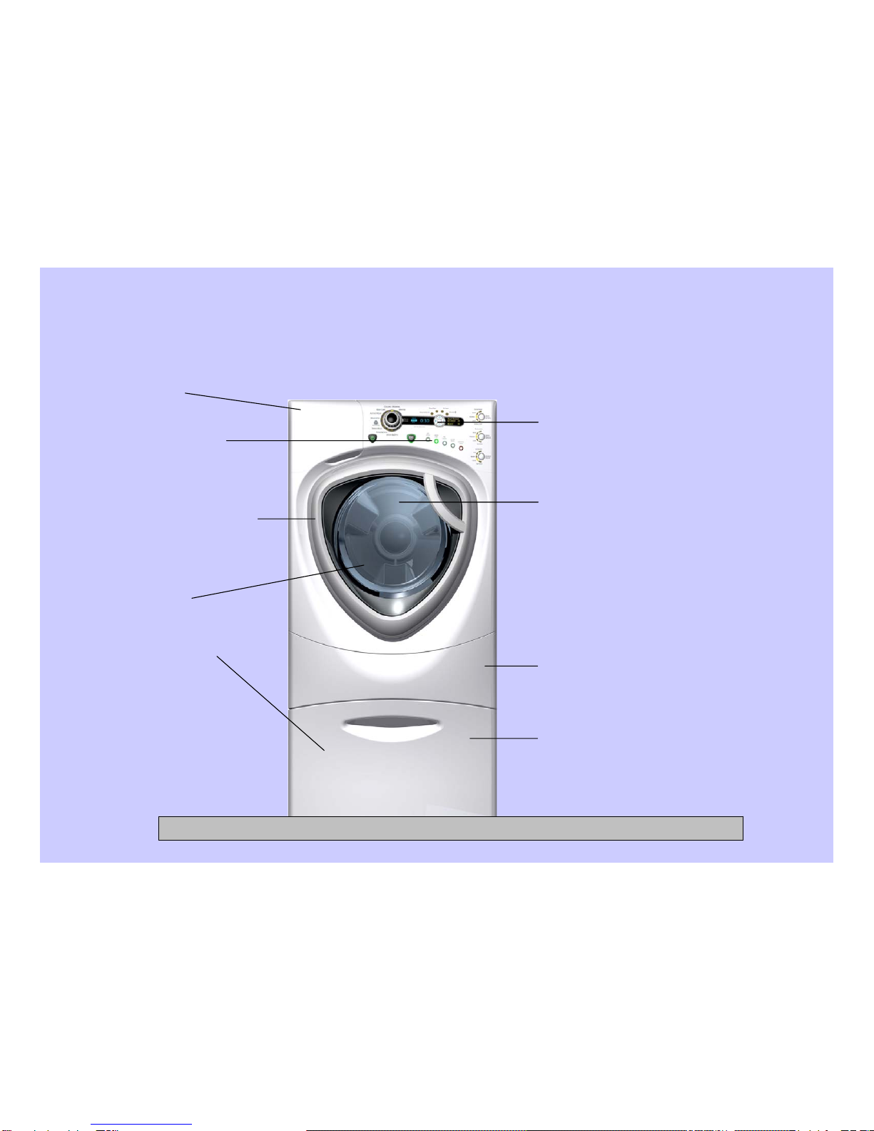
GE Profile ENERGY STAR WPDH8800J Installation instructions

New GE Profile Front Load Washer
WPDH8800J
Pub # 08-MAN-AW-04Robert Gauthier, Training & Technical Support (31-9168)

2
IMPORTANT SAFETY NOTICE
Warning: This information is intended for use by individuals possessing
adequate backgrounds of electrical, electronic and mechanical experience.
Any attempt to repair a major appliance may result in personal injury and
property damage. The manufacturer or seller cannot be responsible for the
interpretation of this information, nor can it assume any liability in connection
with its use.
CAUTION
To avoid personal injury while servicing this unit, disconnect power before
servicing. If grounding wires, screws, straps, clips, nuts, or washers used to
complete a path to ground are removed for service, they must be returned to
their original position and properly fastened.
CONFIDENTIAL AND PROPRIETARY INFORMATION-NOT FOR PUBLIC DISCLOSURE. September 2008

3
Table of Contents
Circuit Board Connections 9
Clean Pump Filter 6
Component Locator Views7, 8
Control Board15, 16, 17
Control Panel 13, 14
Dampers 48, 49
Diagnostic Tests 55, 56, 57, 58, 59, 60
Dispenser Assembly 23, 24, 25, 26, 27
Door 43, 44, 45, 46, 47
Door Lock 20, 21
Error Codes 61, 62, 63, 64, 65, 66 67
Front Panel 22
GE Profile Washer
–
New Features 5
GE Profile Washer Warranty4
Heater Assembly 36
Inverter 37, 38, 39
Inverter Board10
Line Filter 18, 19
Motor Assembly 40, 41, 42
Power Board Assembly 28, 29
Power Supply Board (rear cover off) 12
Power Supply Board (rear cover on)11
Pump 35
Schematic 68
Service Test Mode 50, 51, 52, 53, 54
Water Level Control 30, 31, 32, 33
Water Valve 34
CONFIDENTIAL AND PROPRIETARY INFORMATION-NOT FOR PUBLIC DISCLOSURE. September 2008

4
GE Profile Washer Warranty
For The Period Of:
One Year Any part From the date of original purchase.
Any part of the washer which fails due to a defect in materials or workmanship. During this
limited one-year warranty, GE will also provide, free of charge, all labor and related service
costs to replace the defective part.
Second through Fifth Year From the date of the original purchase
The suspension strut assembly, motor and motor controller if any of these parts should fail due
to a defect in materials or workmanship. GE will also replace the washer top panel, front panel
or service panel if they should rust under operating conditions. During this additional three-year
limited warranty, you will be responsible for any labor or related service costs.
Second through Tenth Year From the date of the original purchase
The outer tub and driven pulley if any of these parts should fail due to a defect in materials
or workmanship. During this additional eight-year limited warranty, you will be responsible
for any labor or related service costs.
Lifetime of Product From the date of the original purchase
The washer basket if it should fail due to a defect in materials or workmanship. During this
product lifetime limited warranty, you will be responsible for any labor or related service costs.
CONFIDENTIAL AND PROPRIETARY INFORMATION-NOT FOR PUBLIC DISCLOSURE. September 2008

5
Increased Basket Capacity:
Minimum 3.35 DOE [3.9 IEC]
Modern Control Interface:
GE designed controls with VFD,
Radial Knob, and Keypad
New Front Panels & Door:
New panels and door
assembly to mount on
Magellan cabinet chassis
Quiet Pack:
Sound insulation added for lower
noise
Communication with
Dryer:
Internal harness and
connector for sending
cycle information to Dryer
Higher Spin Speed:
Minimum 1300 RPM
Bulk Dispense Ready:
All units with built in
tubing and wiring
connection located on rear
of unit, ready for future
Bulk Dispenser Module
program
Tall Pedestal Option:
14” Tall Pedestal with Drawer for
more storage space
Improved Dispenser:
GE Profile Washer – New Features
CONFIDENTIAL AND PROPRIETARY INFORMATION-NOT FOR PUBLIC DISCLOSURE. September 2008

6
Clean Pump Filter
Due to the nature of the front-load washer, it is sometimes possible for small
articles to pass to the pump. The washer has a filter to capture lost items so they
are not dumped to the drain.
To retrieve lost items, clean out the pump filter.
1) Using a coin in the notch on the door, open the
access door.
2) Place a shallow pan or dish under the pump
access door and towels on the floor in front of
the washer to protect the floor. It is normal to
catch about a cup of water when the filter is
removed.
3) Turn the pump filter counterclockwise and
remove the filter.
4) Clean the debris from the filter.
5) Replace the filter and turn clockwise to the
marked position.
6) Close the access door.
CONFIDENTIAL AND PROPRIETARY INFORMATION-NOT FOR PUBLIC DISCLOSURE. September 2008

7
Component Locator Views
Top View
CONFIDENTIAL AND PROPRIETARY INFORMATION-NOT FOR PUBLIC DISCLOSURE. September 2008

8
Front View
CONFIDENTIAL AND PROPRIETARY INFORMATION-NOT FOR PUBLIC DISCLOSURE. September 2008

9
Circuit Board Connections
Control Board
Input from
Power Board
VFD (Vacuum Fluorescent Display)
CONFIDENTIAL AND PROPRIETARY INFORMATION-NOT FOR PUBLIC DISCLOSURE. September 2008

10
Inverter Board
CONFIDENTIAL AND PROPRIETARY INFORMATION-NOT FOR PUBLIC DISCLOSURE. September 2008

11
Power Supply Board (rear cover on)
Motor tachometer
J79
L1 door lock switch, heater, N to inverter, N to bulk dispenser board, N to power filter
J11
Bulk dispenser switch, dispense position switch, heater temperature thermistor, door lock switch
J6
Detergent and softener level sensors
J7
Pressure switch: foam, main, and overflow switches
J5
7V and 12V to UI, LIN bus, ground to UI and inverter, Ezlink tx, tx, and 5V to inverter
J4
Door lock and unlock solenoids, dispenser motor, hot and cold water valves, water pump
J3
Softener pump, detergent pump motors
J2
L1 output to inverter, door lock switch, heater, and power filter
J1
CONFIDENTIAL AND PROPRIETARY INFORMATION-NOT FOR PUBLIC DISCLOSURE. September 2008

12
Power Supply Board (rear cover off)
CONFIDENTIAL AND PROPRIETARY INFORMATION-NOT FOR PUBLIC DISCLOSURE. September 2008

13
Control Panel
The control panel is held in place with 5 Phillips head screws and 1 tab.
To remove the control panel assembly:
1. Remove the top panel.
2. Pull the dispenser out to the stop
position. Press down on the lock tab.
Pull the dispenser out.
3. Remove the 2 Phillips-head
screws from the control panel
dispenser recess.
4. Remove the 3 (7-mm) hex-head
screws that attach the top of the
control panel to the control panel
brace.
CONFIDENTIAL AND PROPRIETARY INFORMATION-NOT FOR PUBLIC DISCLOSURE. September 2008

14
Control Panel (cont.)
5. Lift the top edge of the panel to
disengage the tab that holds the top
of the panel in place.
6. Lift the panel from the cabinet.
7. Disconnect the wire harness from the
control panel.
Note: When installing the control panel,
place the panel pin in the locator hole
in the top right-side of the front panel
before engaging the tab.
CONFIDENTIAL AND PROPRIETARY INFORMATION-NOT FOR PUBLIC DISCLOSURE. September 2008

15
Control Board
The control board detected a critical failure condition. Certain functions of the washer
will not operate. The VFD will show the fault code in the service test mode. The fault
code can only be removed in the service test mode. (See Service Test Mode.)
Fault
A cycle is completed. LEDs and VFD on the front panel stay on, all loads are turned
off. The door is unlocked. The control board remains in this mode until the door is
opened or after 2 hours have passed.
End of Cycle
The control is stopped by the user during the execution of a cycle. LEDs and VFD on
the front panel stay on. All loads are turned off. The door is unlocked. The control
board is ready to take user input to either modify, resume, or cancel the cycle.
Pause
The control board is executing the currently selected cycle. The door is locked.Run
A cycle is selected with the appropriate load selections and options. LEDs and VFD on
the front panel are on. The door is unlocked. The control board is ready to take user
input to either modify cycle selections or start a selected cycle.
Standby
No cycle is selected. All LEDs, VFD on front panel, load selections, and options are
off. The door is unlocked. The control board is ready to take input from user.
Idle
DescriptionMode Name
The control board is mounted in a housing that is attached to the inside of the control panel. The
control board and housing are replaced as an assembly. The control board assembly is held in
place by 4 (6-mm) hex-head screws. The control board is programmed to recognize 6 modes of
operation.
Operation of the control board can be checked by using the service test mode. (See Service Test
Mode.)Specific failures associated with the control board can initiate error codes E1, E2, E10, and E26.
(See Service Test Mode.)

16
Remove the control board assembly:
1. Remove the control panel. (See 1. Control Panel.)
Note: In the following step, the knob is held in place by 4 plastic clips and may require
some effort to remove.
2. Remove the knob by pulling it straight out.
3. Remove the 4 (6-mm) hex-head screws that hold the control board assembly to
the control panel.
4. Remove the control board assembly
from the control panel.
5. Remove the cycle selection buttons.
CONFIDENTIAL AND PROPRIETARY INFORMATION-NOT FOR PUBLIC DISCLOSURE. September 2008

17
VFD (Vacuum Fluorescent Display)
To remove the VFD:
1. Remove the control panel. (See 1. Control Panel.)
2. Disconnect the wire harness from the VFD.
3. Press the 2 tabs that hold the VFD to the control panel, lift the VFD and remove
it from the 2 guides at the bottom.
CONFIDENTIAL AND PROPRIETARY INFORMATION-NOT FOR PUBLIC DISCLOSURE. September 2008

18
Line Filter
The line filter helps to smooth out any fluctuations in voltage, protecting the control board
and providing more reliable operation. The line filter is installed on the interior side of the
rear panel, and is located left of the water valve.
To check the line filter, look for the outer surface to be burnt by heat or a power surge.
The filter resistance should be approximately 0 Ωbetween the black (top) wire terminals
and 0 Ωbetween the white (bottom) wire terminals.
To remove the line filter:
1. Remove the single black (top) and single white (bottom) wires.
2. Disconnect the wire harness by pressing the tab and pulling outward.
Note: The ground wires attached to the line filter use releasing locking tabs.
ELECTRICAL TERMINAL RELEASE/LOCKING TAB
CONFIDENTIAL AND PROPRIETARY INFORMATION-NOT FOR PUBLIC DISCLOSURE. September 2008

19
Line Filter (cont.)
3. Press the locking tab on each
terminal and remove the 2
ground wires.
4. Remove the 2 (7-mm) hex-
head screws that hold the filter
to the frame.
5. Move the filter to the right.
CONFIDENTIAL AND PROPRIETARY INFORMATION-NOT FOR PUBLIC DISCLOSURE. September 2008

20
Door Lock
The door lock contains a door switch and solenoid operated locking and unlocking
mechanism.
The door locks when a cycle is entered (wake-up routine) and during every cycle. The
door unlocks at the completion of a cycle. The door will not open when:
The foam switch is open
Water temperature is above 130°F (54°C)
Wash basket is rotating
Specific failures associated with the door lock can initiate error codes E11 thru E13, and
E28. (See Service Test Mode.)
The door lock is held to the front panel with 3 Phillips-head screws. The door lock is
accessed from the front of the washer when the right side of the gasket is partially pulled
back.
CONFIDENTIAL AND PROPRIETARY INFORMATION-NOT FOR PUBLIC DISCLOSURE. September 2008
Other manuals for Profile ENERGY STAR WPDH8800J
2
Table of contents
Other GE Washer manuals

GE
GE WCSR4170G4WW User manual

GE
GE 175D1807P270 User manual

GE
GE GFWH1400DWW Original instructions

GE
GE Profile PTW7O5 Original instructions

GE
GE WSLP1500H0WW How to use

GE
GE Washers User manual

GE
GE WMXR3080T User manual

GE
GE WPSE7003 User manual

GE
GE GFWR4805 Original instructions

GE
GE GTW330 Original instructions
Popular Washer manuals by other brands

Haier
Haier HWM100-FD756DD user manual

Panasonic
Panasonic NA-F100B3 Operating instructions & installation instructions

Siemens
Siemens WM16Y590GB Instruction manual and installation instructions

Electrolux
Electrolux EWT 1011 Instruction book

LG
LG T0102HFWP owner's manual

Maytag
Maytag MHW8200FW Use & care guide