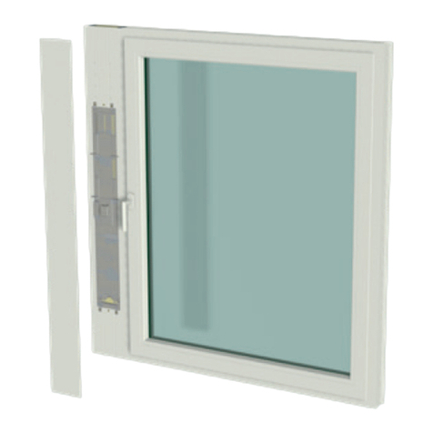
GEALAN CAIRE smart User manual

Ventilation system
GEALAN-CAIRE smart
Operating manual
English translation of the German original operating manual
Last updated: 02/2021

Table of contents
Notes on the manual and the manufacturer ........................................................... 4
Keeping the manual available ........................................................................................4
Design features in the text..............................................................................................4
Design features in figures...............................................................................................5
Manufacturer’s address ..................................................................................................5
Copyright ........................................................................................................................6
Safety ....................................................................................................................... 7
Intended use...................................................................................................................7
Ban on unauthorised conversions..................................................................................7
Basic safety instructions.................................................................................................7
Preventing property damage..........................................................................................8
Design features of warning notices ................................................................................8
Design features of notes on property damage...............................................................8
Description............................................................................................................... 9
Control elements ............................................................................................................9
Operating modes and LED indicators ..........................................................................10
Task and function .........................................................................................................11
Power-saving mode......................................................................................................11
Frost protection monitoring...........................................................................................12
Filters............................................................................................................................12
Cover for closing the air ducts......................................................................................12
Menu items...................................................................................................................13
Technical data ..............................................................................................................14
Name plate ...................................................................................................................14
Operating the ventilation system.......................................................................... 15
Operating the ventilation system with the buttons........................................................15
Switching the ventilation system on and off.......................................................15
Switching operating modes................................................................................16
Selecting menu items.........................................................................................17
Operating the ventilation system with the GEALAN Home app...................................18
Downloading the GEALAN Home app...............................................................18
Establishing a WLAN connection.......................................................................18

Changing the filters................................................................................................20
Maintaining the ventilation system........................................................................23
Troubleshooting.....................................................................................................24
Disposal..................................................................................................................26
Disposing of the filters.................................................................................................. 26
Disposing of the ventilation system ............................................................................. 26

Notes on the manual and the manufacturer
4
Notes on the manual and the manufacturer
This manual will help you to safely operate the ‘GEALAN-CAIRE smart’
ventilation system. The ‘GEALAN-CAIRE smart’ ventilation system is referred
to as the ‘ventilation system’ for short below.
Keeping the manual available
This manual forms part of the ventilation system.
Ensure that this manual is available to the user at all times.
Supply this manual with the ventilation system if you ever sell it or pass it on
in any other way.
Design features in the text
Various elements of this manual are provided with specified design features.
This allows you to easily distinguish between the following elements:
Normal text
•Lists
Call to action
Table headings are in bold.
Tips contain additional information.

Notes on the manual and the manufacturer
5
Design features in figures
When elements of a figure are referred to in a key or in the text, they are given
a number (1). Numbering starts with the number 1 for each figure. Important
details are magnified with magnifying glass views.
Manufacturer’s address
GEALAN Fenster-Systeme GmbH
Hofer Strasse 80
95145 Oberkotzau, Germany
Tel.: +49 (0)92 86 77-0
Fax: +49 (0)92 86 77-22-22
Web: www.gealan.de

Notes on the manual and the manufacturer
6
Copyright
This manual contains information that is subject to copyright. This manual may
not be copied, printed, filmed, processed, reproduced or distributed in any
form, either in whole or in part, without the prior written permission of GEALAN
Fenster-Systeme GmbH.
©2020 GEALAN Fenster-Systeme GmbH
All rights reserved.

Safety
7
Safety
Intended use
The ventilation system is used to aerate and ventilate frost-free rooms. It can
be used in private or semi-public areas.
Intended use includes reading and understanding this manual, as well as
observing and following all the information contained in this manual, especially
the safety instructions.
Any other use is expressly deemed to be unintended.
Ban on unauthorised conversions
Unauthorised conversions or modifications to the ventilation system can result
in serious or even fatal injuries.
Do not make any modifications to the ventilation system’s components.
Basic safety instructions
Incorrect handling of the ventilation system can result in serious injury and
death.
Do not place any objects on the ventilation system.
Only use the ventilation system if it is in a technically perfect condition.
Contact your specialist dealer immediately if you notice any damage.
Have the ventilation system dismantled and repaired by specialist
personnel.
Have the ventilation system dismantled and disposed of by specialist
personnel at the end of its service life.

Safety
8
Preventing property damage
Obstacles can lead to malfunction.
Ensure that there are no obstacles between the ventilation unit and the
mobile terminal device if possible.
If you have problems with WLAN reception, try removing the following
obstacles:
•Furniture
•Bluetooth devices (e.g. wireless keyboards, wireless headphones, etc.)
•Plants
•Electrical appliances (e.g. microwave, wireless cameras, etc.)
•Water-carrying elements.
Design features of warning notices
WARNING
Notes with the word WARNING warn of a dangerous situation
that may potentially lead to death or serious injury.
Design features of notes on property damage
ATTENTION!
These notices warn against situations that lead to property
damage.

Description
9
Description
Control elements
No.
Name
1
Button for operating the ventilation system
2
Fan cover for closing the air ducts (under the cover strip):
When opened: Fan unit switched on
When closed: Fan unit switched off
–
External button for operating the ventilation system (not shown)

Description
10
Operating modes and LED indicators
Operating
mode or
status
LED 1
LED 2
LED 3
LED 4
LED 5
LED 6
Initialisation
phase
Purple
Purple
Purple
Purple
Purple
Purple
Standby
mode
Yellow
–
–
–
–
–
Power
levels in
manual
mode:
Level 1
Green
–
–
–
–
–
Level 2
Green
Green
–
–
–
–
Level 3
Green
Green
Green
–
–
–
Level 4
Green
Green
Green
Green
–
–
Level 5
Green
Green
Green
Green
Green
–
Automatic
mode
–
–
–
–
–
Green
Frost
protection
or moisture
protection
Blue
Blue
Blue
Blue
Blue
Blue
Night
cooling
Turquoise
Turquoise
Turquoise
Turquoise
Turquoise
Turquoise
Cover
closed
–
Red
Red
Red
Red
–
Filter
change
necessary
Flashes orange alternately with the operating mode (e.g. alternately
three green LEDs and six orange LEDs at level 3)
Filter
change
mandatory
All LEDs flash orange
Other
errors
All LEDs flash red alternately with the error code

Description
11
Task and function
The ventilation system is used to aerate and ventilate frost-free rooms. It can
be used in private areas (living rooms, bedrooms, kitchens, showers,
bathrooms, storage rooms) or semi-public areas (offices, hotel rooms, daycare
centres, nursing homes).
Used, warm room air is extracted as exhaust air and discharged to the outside
as outgoing air. At the same time, fresh outside air is drawn in and introduced
into the rooms as filtered supply air.
The ventilation system has a position sensor. The position sensor detects
when the ventilation system is not in the correct position in the ventilation
profile. In this case, it blocks operation of the ventilation system.
The ventilation system has the following operating modes:
•a manual mode
•a standby mode
•an automatic mode.
In automatic mode, the speed of the fans is controlled according to the
humidity. In manual mode, the speed of the fans is controlled according to the
set power level.
The ventilation system has one button and six RGB LEDs. It can also be
equipped and controlled with an external button as an option.
In addition, the ventilation system can also be controlled over a WLAN. WLAN
control is carried out using the GEALAN Home app.
The LEDs indicate the current state of the ventilation system, filter change and
errors. When the ventilation system is in operation, the LEDs switch on
automatically. They switch off after two minutes by default. LED switch-off can
be set in the GEALAN Home app.
Power-saving mode
When the ventilation unit is in standby mode and the set time to LED switch-
off has elapsed, the ventilation unit starts power-saving mode. Power-saving
mode is not displayed separately. Access to the ventilation system through the
GEALAN Home app is still possible. The power-saving mode is automatically
ended as soon as the ventilation system is operated or the LED switch-off is
disabled.

Description
12
Frost protection monitoring
The ventilation system has frost protection monitoring. Frost protection
monitoring prevents freezing of and thus damage to the heat exchanger. Frost
protection monitoring is active in all operating modes.
The heat exchanger’s exhaust air duct may start to freeze due to condensate
formation and sub-zero outdoor temperatures. So the exhaust air duct’s cross-
section through the heat exchanger is continuously reduced. As a result, less
heat is transferred to the supply air. This causes a significant drop in supply air
temperature.
The system continuously monitors the supply air temperature. As soon as the
supply air temperature drops too low, the system automatically switches to
frost protection mode.
The supply air fan is switched off in frost protection mode. The exhaust air fan
runs continuously at level 2. It ensures defrosting and drying of the heat
exchanger.
The frost protection ends automatically as soon as the danger to the heat
exchanger has passed. Once frost protection has ended, the ventilation unit
continues to run in the operating mode that was active previously.
Filters
The ventilation unit has two filters for supply air and exhaust air. The filters
have a limited service life and have to be changed regularly. The filters’
service life depends on the volume of air that passes through them and is
therefore dependent on the ventilation unit’s operating mode.
The filters have their own data memory. The operating hours and the running
time are stored in this data memory depending on the operating mode.
When the service life of one or both of the filters is almost reached (after 11
months in level 1), ‘Filter change necessary’ is indicated. However, the
ventilation unit continues to operate normally.
When the service life of one or both of the filters is finally reached (after a total
of 13 months in level 1), ‘Filter change mandatory’ is indicated. The ventilation
unit can no longer operate.
‘Filter change necessary’ and ‘Filter change mandatory’ are indicated by
orange LEDs (see page 10 regarding this matter). The LED closest to the filter
to be changed is displayed slightly darker than the other LEDs. This informs
you which filter needs to be replaced.
Once the filters have been changed, the LED indicator goes out and the
ventilation unit automatically continues in the last operating mode.
Cover for closing the air ducts
A cover is fitted over the fans (under the cover strip). This cover allows the
airways to be closed. Both of the ventilation unit’s fans switch off when the

Description
13
cover is closed. As soon as the cover is opened again, the ventilation unit
resumes operation in the most recently set operating mode.
Menu items
The ventilation system has a settings menu. You can set or display the
following items in this menu:
•Delete errors
•Switch on WLAN
•Switch off WLAN
•Reset WLAN
•Restart communication processor.
The ‘Switch on WLAN’ menu item is displayed when the WLAN is switched off.
The ‘Switch off WLAN’ menu item is displayed when the WLAN is switched on.
Delete errors
You can delete the errors that have occurred in this menu item.
Enable WLAN
You can enable the WLAN in this menu item.
Disable WLAN
You can disable the WLAN in this menu item.
Reset WLAN
You can reset all of the WLAN settings with the exception of the device name
in this menu item. To this end, the WLAN is disabled, all the saved settings
are deleted and the WLAN is reconfigured. The communication processor is
restarted after a few seconds. The ventilation unit logs on as a software
access point with the original password, as it did during initial commissioning
process, and can be reconfigured.
Restart communication processor
You can restart the communication processor in this menu item (e.g. if there
are problems with the WLAN connection). You do not have to disconnect the
ventilation system from the power supply during this process.

Description
14
Technical data
Fan unit
Dimensions (L × W × H)
126 × 86 × 34 mm
Weight
2.4 kg
Number of fans
2
Output
34 W
Power supply
24 V
Volume flow
4 –40 m3/h
Power supply unit
Dimensions (L × W × H)
163 × 43 × 32 mm
Weight
500 g
Output
60 W
Input voltage
100 –230 V AC
Output voltage
24 V DC
Protection class
IP67
Name plate
The name plate is located on the front of the ventilation system. You will find
the following information on the name plate:
•Manufacturer’s name and contact details
•Country of manufacture
•Model name
•Year of manufacture
•QR code
•CE mark
•WEEE Directive mark (rubbish bin)
•Input voltage range
•Serial number
•Item number
•MAC address.

Operating the ventilation system
15
Operating the ventilation system
You can operate the ventilation system as follows:
•with the button on the unit
•with the external button
•with the GEALAN Home app.
Operating the ventilation system with the buttons
Operation is identical with both buttons. So reference is always made to
both buttons when a button is mentioned below.
Switching the ventilation system on and off
Slide the cover for closing the air ducts (1) to the open position.
The fans switch on. Following switch-on for the first time (initial commissioning
process or after a power failure), the fan switches to automatic mode. When
switched on again, the fan unit starts in the operating mode that was active
last.
Slide the cover for closing the air ducts (1) to the closed position.
The fan unit’s fans switch off. The middle four LEDs light up red.

Operating the ventilation system
16
Switching operating modes
The ventilation system has the following operating modes:
•a manual mode
•a standby mode
•an automatic mode.
In manual mode, you can select the power levels (1, 2, 3, 4 and 5) and the
standby mode. Proceed as follows to select the standby mode or a power
level:
Ensure that the cover for closing the air ducts is in the open position.
Press the button once to switch to the next power level or to standby mode.
The set power level or standby mode is indicated by the LEDs.
Repeat this step until the desired power level or standby mode is reached.
The unit switches through the mode and levels in the following sequence:
•Standby mode
•Power level 1
•Power level 2
•Power level 3
•Power level 4
•Power level 5.
The LEDs (in the case of horizontal installation: starting from the left; in the
case of vertical installation: starting from the bottom) indicate the current fan
state:
•Standby mode is active: one LED lights up yellow.
•Power level 1 is active: one LED lights up green.
•Power level 2 is active: two LEDs light up green.
•Power level 3 is active: three LEDs light up green.
•Power level 4 is active: four LEDs light up green.
•Power level 5 is active: five LEDs light up green.
Operation in level 5 is limited to a maximum of 60 minutes to prevent the
power supply unit from overheating. The ventilation unit automatically
switches down to level 4 after 60 minutes in level 5.
Proceed as follows to switch from manual mode to automatic mode:
Press and hold the button for three seconds.
The first LED from the right or the first LED from the top lights up green. The
ventilation system is now in automatic mode.

Operating the ventilation system
17
Proceed as follows to switch from automatic mode to manual mode:
Press and hold the button again for three seconds.
The ventilation system is now in manual mode.
Starting from the left or the bottom, the number of green LEDs indicates which
ventilation level is active.
Selecting menu items
Proceed as follows to select a menu item:
Press and hold the button for five seconds.
The first three LEDs flash purple. The settings menu opens.
The last three LEDs indicate the relevant menu item. The unit switches to the
next menu item every six seconds. The settings menu is closed once the last
menu item is displayed.
Press the button once to select the relevant menu item.
The menu item currently displayed is selected and the settings menu is exited.
Refer to the table below for the colours of the LEDs for the relevant menu
item:
No.
Menu item
LED 1
LED 2
LED 3
LED 4
LED 5
LED 6
1
Delete errors
Flashing purple
Red
Red
Red
2
Switch on WLAN
Blue
Blue
Green
3
Switch off WLAN
Blue
Blue
Red
4
Reset WLAN
Blue
Blue
Purple
5
Restart
communication
processor
Yellow
Yellow
Yellow
The ventilation unit continues to operate normally throughout the entire
process.

Operating the ventilation system
18
Operating the ventilation system with the GEALAN Home app
You must perform the following activities to use the ventilation system with the
GEALAN Home app:
•Download the GEALAN Home app
•Establish a WLAN connection
For this, you will need:
•a tablet
•or a smartphone.
Operating system: Android or iOS
Downloading the GEALAN Home app
You can use the following links:
•www.gealan.de/gealan-home-app-android
•www.gealan.de/gealan-home-app-ios
Download the app that’s suitable for your terminal device’s operating
system.
Follow the instructions in the app.
Establish a WLAN connection.
Establishing a WLAN connection
ATTENTION!
Obstacles (e.g. furniture, plants, Bluetooth devices, etc.) can
cause malfunctions.
Ensure that there are no obstacles (e.g. furniture, plants,
Bluetooth devices, etc.) between the ventilation system and
the mobile terminal device.
Enable the WLAN according to the section entitled ‘Selecting menu items’
(see page 17 regarding this matter).
After switching on the WLAN for the first time (or after resetting the WLAN
settings), the ventilation unit works as a software access point (SoftAP).
Connect your device to the ventilation unit’s software access point (SoftAP).
The WLAN network you need to connect to is displayed as
GEALAN_AP_XXXXXX. The last six characters identify the ventilation unit,
e.g. GEALAN_AP_188CC0. If you use several ventilation units, several WLAN
networks are displayed too.

Operating the ventilation system
19
The six characters (without dots) are taken from the MAC address on the
name plate.
The SoftAP mode is secured with a password. The password is made up of
your ventilation system’s serial number (SN) and as many zeros as necessary
to reach 12 digits including the serial number (SN). For example, the serial
number (SN) 158329 results in the password ‘SN0000158329’. The length of
the serial number may vary.
The serial number (SN) is attached to the ventilation unit. If the sticker was
removed by mistake, you can ask your specialist dealer for the serial number
with the WLAN SSID. For security reasons, you must change the password
after logging in for the first time. If you forget the password, you must reset all
of the WLAN settings in the settings menu (see page 17 regarding this
matter).
After connecting your device to the software access point (SoftAP), you can
use the ventilation unit in this mode. We recommend integration in a home
network.
To do this, follow the instructions in the GEALAN Home app.

Changing the filters
20
Changing the filters
When the service life of one or both of the filters is finally reached (after a total
of 13 months in level 1), ‘Filter change mandatory’ is indicated. The ventilation
unit can no longer operate.
‘Filter change necessary’ and ‘Filter change mandatory’ are indicated by
orange LEDs (see page 10 regarding this matter). The LED closest to the filter
to be changed is displayed slightly darker than the other LEDs. This informs
you which filter needs to be changed. Proceed as follows to change the filters:
Switch off the ventilation system.
Remove the cover strip (1).
Other manuals for CAIRE smart
1
Table of contents
Other GEALAN Fan manuals
Popular Fan manuals by other brands

Ortech
Ortech Supreme Series quick start guide

Casablanca
Casablanca M8515-01 installation manual

NovingAIR
NovingAIR PHANTOM Series Installation, use and maintenance manual

Ortech
Ortech OD22025 manual

Modern Forms
Modern Forms Morpheus III installation instructions

TREVIDEA
TREVIDEA G3 Ferrari 4 STAGIONI user manual