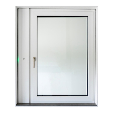
GEALAN CAIRE smart User manual

Ventilation system
GEALAN-CAIRE smart
Assembly manual
English translation of the German original manual
Last updated: 02/2021

Table of contents
Notes on the manual and the manufacturer ........................................................... 4
Keeping the manual available ........................................................................................4
Design features in the text..............................................................................................4
Design features in figures...............................................................................................5
Manufacturer’s address ..................................................................................................5
Copyright ........................................................................................................................6
Safety ....................................................................................................................... 7
Intended use...................................................................................................................7
The operator’s responsibility ..........................................................................................7
Personnel qualifications..................................................................................................7
Ban on unauthorised conversions..................................................................................7
Basic safety instructions.................................................................................................8
Preventing severe and deadly injuries.................................................................8
Avoiding minor injuries.........................................................................................8
Avoiding property damage and malfunctions.................................................................8
Design features of warning notices ................................................................................9
Description............................................................................................................. 10
Scope of delivery..........................................................................................................10
Ventilation profile..........................................................................................................12
Fan unit –inside and outside........................................................................................13
Operating modes and LED indicators ..........................................................................14
Power supply unit and PSU holder...............................................................................15
Accessories ..................................................................................................................16
Required accessories.........................................................................................16
Optional accessories..........................................................................................16
Task and function .........................................................................................................17
Technical data ..............................................................................................................18
Name plate ...................................................................................................................18
Transporting and storing the ventilation system ................................................. 19
Unpacking the ventilation system and checking the scope of delivery .............. 20
Assembling the ventilation system....................................................................... 21
Required tools ..............................................................................................................21
Prerequisites for assembly ...........................................................................................21
Installing the ventilation system in the ventilation profile..............................................21
Inserting the filters ........................................................................................................29
Attaching hook-and-loop fastener tape ........................................................................30

Positioning the sticker over the button......................................................................... 31
Connecting the external button.................................................................................... 31
Cable assignment for the flush-mounted button................................................ 31
Enabling the external button........................................................................................ 31
Commissioning the ventilation system.................................................................32
Elimination of faults ...............................................................................................34
Dismantling the ventilation system.......................................................................35
Disposing of the ventilation system......................................................................36
Warranty .................................................................................................................37

Notes on the manual and the manufacturer
4
Notes on the manual and the manufacturer
This manual will help you to safely assemble the ‘GEALAN-CAIRE smart’
ventilation system in the ventilation profile on the window. The ‘GEALAN-
CAIRE smart’ ventilation system is referred to as the ‘ventilation system’ for
short below.
Keeping the manual available
This manual forms part of the ventilation system.
Ensure that this manual is available to the user at all times.
Supply this manual with the ventilation system if you ever sell it or pass it on
in any other way.
Design features in the text
Various elements of this manual are provided with specified design features.
This allows you to easily distinguish between the following elements:
Normal text
•Lists
Call to action
Table headings are in bold.
Tips contain additional information.

Notes on the manual and the manufacturer
5
Design features in figures
When elements of a figure are referred to in a key or in the text, they are given
a number (1). Numbering starts with the number 1 for each figure. Important
details are magnified with magnifying glass views.
Manufacturer’s address
GEALAN Fenster-Systeme GmbH
Hofer Strasse 80
95145 Oberkotzau, Germany
Tel.: +49 (0)92 86 77-0
Fax: +49 (0)92 86 77-22-22
Web: www.gealan.de

Notes on the manual and the manufacturer
6
Copyright
This manual contains information that is subject to copyright. This manual may
not be copied, printed, filmed, processed, reproduced or distributed in any
form, either in whole or in part, without the prior written permission of GEALAN
Fenster-Systeme GmbH.
©2020 GEALAN Fenster-Systeme GmbH
All rights reserved.

Safety
7
Safety
Intended use
The ventilation system is used to aerate and ventilate frost-free rooms. It can
be used in private or semi-public areas.
Intended use includes reading and understanding this manual, as well as
observing and following all the information contained in this manual, especially
the safety instructions.
Any other use is expressly deemed to be unintended.
The operator’s responsibility
The operator must ensure that all the accident prevention regulations are
observed.
The operator must ensure that only qualified and authorised assembly
personnel carry out work on the ventilation system.
The operator must ensure that the ventilation system is only operated in a
secure (WPA 2-encrypted) WLAN network.
Personnel qualifications
This assembly manual is intended for specialists from specialist companies
who are trained in the assembly and installation of ventilation systems. The
following knowledge and experience are required for assembly personnel:
Knowledge that improper assembly of the ventilation system can cause
accidents
Ability to install the ventilation system in the ventilation profile with the help
of this manual
Ability to assess hazards that can be caused by electrical voltage and
current
Ability to measure voltage, current and resistances
Ability to establish electrical connections
Ability to detect defective electronic components.
Ban on unauthorised conversions
Unauthorised conversions or modifications to the ventilation system can result
in serious or even fatal injuries.
Do not make any modifications to the ventilation system’s components.

Safety
8
Basic safety instructions
Preventing severe and deadly injuries
Use the ventilation system only in areas where there is no corrosive or
explosive atmosphere (dust, vapour or gas).
Have all work on the connection to the mains exclusively carried out by a
qualified electrician.
Observe the current VDE [...] or the corresponding country-specific
regulations for all work on the mains.
Before carrying out any work on the ventilation system, ensure that the
power supply unit and the connections are dead.
Use insulated tools when connecting the ventilation system.
Ensure that the ventilation system’s mains connection cable is undamaged.
Do not place any objects on the ventilation system.
Only use the ventilation system if it is in a technically perfect condition.
Send the ventilation system to your specialist dealer immediately if you
notice any damage. Have it repaired there by specialist personnel.
Avoiding minor injuries
Sharp-edged burrs can cause cuts.
Deburr machined material.
Use cut-resistant gloves when assembling the ventilation system.
Avoiding property damage and malfunctions
Obstacles can lead to malfunction.
Ensure that there are no obstacles between the ventilation unit and the
mobile terminal device if possible.
If you have problems with WLAN reception, try removing the following
obstacles:
•Furniture
•Bluetooth devices (e.g. wireless keyboards, wireless headphones, etc.)
•Plants
•Electrical appliances (e.g. microwave, wireless cameras, etc.)
•Water-carrying elements.

Safety
9
Design features of warning notices
DANGER
Notes with the word DANGER warn of a dangerous situation
that will lead to death or serious injury.
WARNING
Notes with the word WARNING warn of a dangerous situation
that may potentially lead to death or serious injury.

Description
10
Description
Scope of delivery
No.
Name
1
Screws for assembling the fan unit (Ø 4 × 25 mm)
2
Power supply unit
3
Fan unit

Description
11
The scope of delivery also includes the following:
•Assembly and operating manual
•Button for control sticker
•Template for the sticker
•Set of screws for the power supply unit
•Set of screws for fans
•Two filters
•Damping rings

Description
12
Ventilation profile
No.
Name
1
Installation opening and mounting hole for the power supply unit
2
Installation opening for the fan unit
3
Openings for supply air and exhaust air

Description
13
Fan unit –inside and outside
No.
Name
1
Mains cable (24 V)
2
Openings for supply air and exhaust air with ventilation flaps (outside)
3
Tabs
4
Filter flaps
5
Button for operating the ventilation system
6
Control unit with LEDs
7
Cover of the openings for supply air and exhaust air (inside):
When closed: The fan unit’s fans switch off
When opened: The fan unit’s fans switch on

Description
14
Operating modes and LED indicators
Operating
mode or
status
LED 1
LED 2
LED 3
LED 4
LED 5
LED 6
Initialisation
phase
Purple
Purple
Purple
Purple
Purple
Purple
Standby
mode
Yellow
–
–
–
–
–
Power
levels in
manual
mode:
Level 1
Green
–
–
–
–
–
Level 2
Green
Green
–
–
–
–
Level 3
Green
Green
Green
–
–
–
Level 4
Green
Green
Green
Green
–
–
Level 5
Green
Green
Green
Green
Green
–
Automatic
mode
–
–
–
–
–
Green
Frost
protection
or moisture
protection
Blue
Blue
Blue
Blue
Blue
Blue
Night
cooling
Turquoise
Turquoise
Turquoise
Turquoise
Turquoise
Turquoise
Cover
closed
–
Red
Red
Red
Red
–
Filter
change
necessary
Flashes orange alternately with the operating mode (e.g. alternately
three green LEDs and six orange LEDs at level 3)
Filter
change
mandatory
All LEDs flash orange
Other
errors
All LEDs flash red alternately with the error code

Description
15
Power supply unit and PSU holder
No.
Name
1
Insertion side
2
Stop
3
Locating hole
4
Mains cable (24 V)
5
Screws (2 × Ø 3.5 × 16 mm)
6
Mains cable (230 V)

Description
16
Accessories
Required accessories
•PSU holder (item no.: 5420 70)
•230 V connection cable (item no.: 5426 99)
•Sealing set (item no.: 5694 99)
Optional accessories
•Connection cable for external button (item no.: 5447 99)
•Insect screen (item no.: 5444)
•Fine dust (F7) replacement filter (item no.: 5428 99)
•(Coarse) dust (G3) replacement filter (item no.: 5427 99)

Description
17
Task and function
The ventilation system is used to aerate and ventilate frost-free rooms. It can
be used in private areas (living rooms, bedrooms, kitchens, showers,
bathrooms, storage rooms) or semi-public areas (offices, hotel rooms, daycare
centres, nursing homes).
Used, warm room air is extracted as exhaust air and discharged to the outside
as outgoing air. At the same time, fresh outside air is drawn in and introduced
into the rooms as filtered supply air.
The ventilation system can be assembled horizontally or vertically on the
window in the ventilation profile. Horizontal installation can only be carried out
above the window.
The ventilation system has a position sensor. The position sensor detects
when the ventilation system is not in the correct position in the ventilation
profile. In this case, it blocks operation of the ventilation system.
The ventilation system has the following operating modes:
•Manual mode
•Standby mode
•Automatic mode.
In automatic mode, the speed of the fans is controlled according to the
humidity. In manual mode, the speed of the fans is controlled according to the
set power level.
The ventilation system can be operated using the built-in button. The
ventilation system can also be equipped and controlled with an external button
as an option. The external button is operated in the exact same way as the
built-in button.

Description
18
Technical data
Fan unit
Dimensions (L × W × H)
126 × 86 × 34 mm
Weight
2.4 kg
Number of fans
2
Output
34 W
Power supply
24 V
Volume flow
4 –40 m3/h
Power supply unit
Dimensions (L × W × H)
163 × 43 × 32 mm
Weight
500 g
Output
60 W
Input voltage
100 –230 V AC
Output voltage
24 V DC
Protection class
IP67
Name plate
The name plate is located on the front of the ventilation system. You will find
the following information on the name plate:
•Manufacturer’s name and contact details
•Country of manufacture
•Model name
•Year of manufacture
•QR code
•CE mark
•WEEE Directive mark (rubbish bin)
•Input voltage range
•Serial number

Transporting and storing the ventilation system
19
Transporting and storing the ventilation system
Transport the ventilation system on a pallet in such a way that it is dry and
protected from frost. Ensure that the pallets are not stacked on top of one
another.
Store the ventilation system in dry and frost-protected areas.

Unpacking the ventilation system and checking the scope of
delivery
20
Unpacking the ventilation system and checking
the scope of delivery
Remove the ventilation system from the packaging.
Keep the original packaging so you can potentially return the ventilation
system to Customer Service.
Check the scope of delivery to ensure that it is correct and complete (see
page 10 regarding this matter).
Check that the ventilation system is undamaged.
Contact your specialist dealer immediately if there are any deviations.
Other manuals for CAIRE smart
1
Table of contents
Other GEALAN Fan manuals
Popular Fan manuals by other brands

Ortech
Ortech Supreme Series quick start guide

Casablanca
Casablanca M8515-01 installation manual

NovingAIR
NovingAIR PHANTOM Series Installation, use and maintenance manual

Ortech
Ortech OD22025 manual

Modern Forms
Modern Forms Morpheus III installation instructions

TREVIDEA
TREVIDEA G3 Ferrari 4 STAGIONI user manual