Geca CTP21 User manual

DIS. 0534014 COD. 27101443 Istruzione / User’s Manual Pag.1/4
Sensore gas per centrali termiche
Remote gas sensor for heating plants
GECA Srl Via E. Fermi 98 -25064 Gussago (Brescia) Italy http://www.gecasrl.it Tel:+39 030/3730218 Fax:+39 030/3730228
GAS
SENSOR
IP44
Caratteristiche tecniche / Technical specifications
Alimentazione / Power supply 12Vdc (-10/+15%) -165mA (1,98 W)
Uscita / Output 4÷20mA Lineare / Linear
Resistenza di carico / Load resistor 100 Ωmax
Campo di misura / Standard range 0 ÷ 20 % LIE / LEL
Sensore / Sensor Catalitico / Catalytic
Tempo di risposta T50 / Response time T50 < 30 secondi / seconds
Precisione / Accuracy ± 10 %
Deriva a lungo termine in aria pulita / Long time drift in pure air <±5 % LIE anno / LEL year
Vita media in aria pulita / Expected life in pure air 10 anni / years
Temp./umidità di funzionamento / Operation Temp./Humidity -10 ÷ +50 °C / 5÷90 % r.h. 40°C
Temp./umidità di immagazzinamento / Storage Temp./Humidity -25 ÷ +55°C / 5÷95 % r.h.
Grado protezione / Rating IP44
Dimensioni / Size 110 x 75 x 70 mm
DESCRIZIONE
I modelli della serie ST441 sono sensori 4÷20mA lineari a
tre fili in grado di rilevare gas combustibili ed utilizzano sen-
sori di tipo catalitico tarabili al 20% LIE per alcuni gas.
L'apparecchio è costituito da una custodia che contiene il
circuito elettronico e i morsetti di collegamento; il sensore è
inserito all'interno del portasensore, posto su coperchio della
custodia.
Gli ST441 vengono normalmente collegati alle nostre cen-
trali di rilevazione gas per centrali termiche come indicato
sopra in Tabella.
FUNZIONAMENTO
Il sensore catalitico è praticamente insensibile alle variazioni
di umidità e temperatura, è in grado di rilevare gas infiam-
mabili e la taratura viene eseguita per il gas che il sensore
deve rilevare.
Per questo può rilevare anche altri gas o solventi infiamma-
bili se sono presenti nello stesso locale.
Il sensore, quando viene alimentato, necessita di un tempo
di preriscaldo di circa 30 secondi. Dopo questo tempo è in
grado di rilevare il gas, ma raggiunge le condizioni di stabilità
ottimali dopo circa 3 ore di funzionamento continuo.
Dopo questo tempo si consiglia di effettuare una verifica in
aria pulita del “4mA” e, solo se necessario, procedere alla
“Regolazione del 4mA” come indicato a pag. 3, per adattare
il sensore alle condizioni ambientali.
GENERAL INFORMATION
The models series ST441, is a three-wire 4÷20mA linear
sensores able to detect combustible gases employing a
catalytic sensor calibrated up to 20% LEL to different gases.
The instrument comprises of a thermoplastic terminal box
which contains the electronic circuit, the connecting termi-
nals and the sensor placed in its housing on the cover.
The ST441 are normally connected to the GECA gas de-
tecting central systems for heating plants, as shown in the
Table above.
OPERATIONAL DESCRIPTION
The catalytic sensor is practically insensitive to humidity and
temperature variations. The sensor being designed to detect
flammable gases and the calibration is carried out with the
specific gas to be detected. Anyway, it can contemporane-
ously detect any other flammable gas that should be present
in the same environment.
When powered, the sensor needs a time of preliminary
heating of about 30 seconds.
After this period, the sensor is able to detect gas even if it
attains the optimum stability conditions after about 3 hours
continual functioning. Therefore, after that time we advise to
check in clean air the “4mA” output.
If is necessary “4mA calibration” can be carried out as ex-
plained on page 3.This calibration is necessary to adjust the
sensor to the environment conditions.
Centraline collegabili a ST441G e ST441M
Detectors which can be connected to the ST441G –ST441M
Modello
Model N°Sensori
Sensors number
CTM31 –CTM21 –CTM11 1
CTP31 –CTP21 1 ÷ 3

DIS. 0534014 COD. 27101443 Istruzione / User’s Manual Pag.2/4
GECA Srl Via E.Fermi 98 -25064 Gussago (Brescia) Italy http://www.gecasrl.it Tel:+39 030/3730218 Fax: +39 030/3730228
Guasti: in caso di guasto del sensore l'uscita "S" va a
0mA (FAULT).
Il segnale viene poi interpretato dalla centralina e se-
gnalato come una situazione di guasto. Questo av-
viene anche se si verifica un'interruzione ai fili di col-
legamento tra sensore e centralina.
Periodo di funzionamento: L'elemento sensibile utilizzato
in questo sensore ha una buona stabilità nel tempo.
In condizioni di funzionamento normale in aria pulita la vita
del sensore è circa 10 anni dalla data installazione.
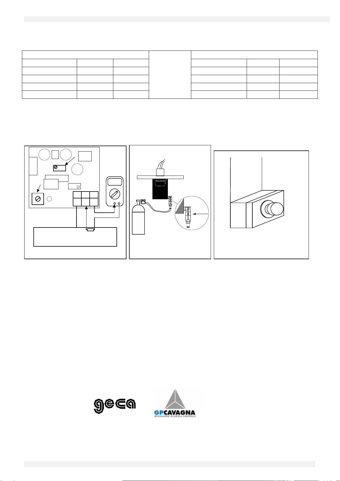
Verifiche Periodiche: Si consiglia di effettuare la verifica di
funzionamento ogni 6 mesi e ogni 2 anni procedere alla ta-
ratura del circuito con miscela Gas/Aria come indicato a
Pag.3.
Nota importante: tenere presente che in ambienti con
situazioni gravose o particolarmente inquinati o con va-
pori di sostanze infiammabili (in particolare solventi), può
essere necessario effettuare più spesso la verifica e/o la
taratura periodica, inoltre la vita utile del sensore può ri-
dursi notevolmente.
INSTALLAZIONE
I sensori vanno installati e posizionati seguendo tutte le
norme nazionali e/o europee vigenti in materia per gli im-
pianti elettrici nei luoghi con pericolo di esplosione e le nor-
me di sicurezza degli impianti.
Posizionamento: gli ST441 devono essere installati in po-
sizione orizzontale. Gli ST441G devono essere posizionati
in basso a non più di 50cm dal pavimento (normalmente 20-
30cm) e entro 1 metro in orizzontale dal centro di pericolo.
Gli ST441M devono essere posizionati in alto a non più di
50cm dal soffitto (normalmente 20-30cm) e entro 1 metro in
orizzontale dal centro di pericolo.
Collegamenti elettrici: sono da effettuare utilizzando il
morsetto a tre poli.
(Per i collegamenti e la distanza vedere anche alle specifi-
che istruzioni delle centraline a cui il sensore va collegato).
Non è necessario utilizzare cavi schermati.
Normalmente la distanza massima dalla centralina cui pos-
sono essere collegati i sensori è di 100 metri con cavi
3x1,5mm2e da 200 metri con cavi 3x2,5mm2.
AVVERTENZE
La taratura è effettuata con gas calibrato. Il trimmer P3 non
deve essere assolutamente manomesso.
La verifica periodica e/o la taratura in campo deve essere
effettuata solo da personale addestrato e autorizzato. In al-
ternativa, si consiglia di effettuare solo la verifica senza toc-
care i trimmer e nel caso i valori non siano quelli richiesti
contattare il nostro laboratorio.
Attenzione: alcune sostanze causano una diminuzione
permanente di sensibilità. Evitare che il sensore venga a
contatto con vapori di Silicone, Tetraetile di Piombo o Esteri
fosfati.
Altre sostanze causano una temporanea perdita di sensibili-
tà. Questi “inibitori” sono gli Alogeni, l’Idrogeno solforato, il
Cloro, gli Idrocarburi clorurati (Trielina o Tetracloruro di car-
bonio).
Dopo un breve tempo in aria pulita, il sensore riprende il
proprio funzionamento normale.
Importante: il sensore utilizzato di tipo catalitico funziona
solo in presenza di Ossigeno.
Faults: In case of sensor damage, the "S" output falls
down to 0mA (FAULT). The signal is then indicated as
a damage situation.
All this happens also when an interruption to the connection
wires between the sensor and the detector occur.
Average life: The sensitive element used in this sensor
has an excellent stability in time. In fresh air and in
normal working condition the sensor's life is about 10
years from the date of installation.
Periodical testing: we advise to carry out working tests
every 6 months. After 2 year we advise to proceed to the
recalibration of the circuit with Gas/Air mixture as explained
on page 3.
Attention: please note that in polluted environments,
where vapours of flammable agents, especially sol-
vents, might be present, the periodical testing and re-
calibrations should be carried out at shorter time in-
tervals. In polluted environments the sensor's life can
be reduced.
INSTALLATION
The sensor must be accurately installed according to
all the national dispositions in force on the safety of
the plants and installation of electric devices in areas
with danger of explosion.
Positioning: the ST441 must be installed in horizontal
position. The ST441G must be placed low at least at
50cm from the floor (normally 20-30cm) and less than
1 meter horizontal distance from the core danger. The
ST441M must be placed low at least at 50cm from
the ceiling (normally 20-30cm) and less than 1 meter
horizontal distance from the core danger.
Electric connections: are to be carried out using the
three-pole terminal (See special instructions enclosed
with the gas detectors). It is not necessary to use
shielded cables. The sensores can be placed at a
max. distance of 100 meters from the gas detector
when 3x1.5mm2cables are used, and 200 meters
with 3x2.5 mm2cables.
WARNING
Calibration is carried out with gas. Absolutely trimmer P3
must not be tampered with.
The calibration routine is to be carried out by trained or
authorised personnel only.
As an alternative it is advised to check the calibration with-
out operating on the trimmers, and in case the values are
not the required ones please apply to our Laboratory.
Warning: some substances cause a permanent reduc-
tion in sensitivity.
Avoid contacts of the sensor with vapours of Silicone
compounds, Tetra-ethyl Lead (petrol antiknock additive)
and Phosphate esters, since they can reduce irremedia-
bly its sensitivity. Some substances produces a tempo-
rary loss of sensitivity. This “inhibitors” include Hydrogen
sulphide, Chlorine, Chlorinated hydrocarbons and alien-
ated compounds.
The sensitivity is recovered after a short period of run-
ning in clear air.
Very Important: the catalytic sensor used will operate only
in presence of Oxygen.
Non usare gas puri o l'accendino direttamente sul sensore
che potrebbe venire irrimediabilmente danneggiato.

DIS. 0534014 COD. 27101443 Istruzione / User’s Manual Pag.3/4
GECA Srl Via E.Fermi 98 -25064 Gussago (Brescia) Italy http://www.gecasrl.it Tel:+39 030/3730218 Fax: +39 030/3730228
Note sui modelli
ST441G (GPL)
ST441G è in grado di rilevare gas fino al 20% del LIE. Il
GPL è un gas più pesante dell'aria, formato da una miscela
composta dal 20÷30% di Propano (C3H8) e dall'80÷70% di
Butano (C4H10).
La densità relativa all'aria è 1,56 per il propano e 2 per il bu-
tano. l LIE (Limite Inferiore di Esplosività) è 2% v/v per il
Propano e 1,5% v/v per il Butano. Le tarature per GPL nor-
malmente sono effettuate con gas Butano.
In Tab.A è indicata la corrispondenza tra il segnale di uscita
in mA e la % LIE.
ST441M (Metano CH4)
ST441M è in grado di rilevare gas fino al 20% del LIE.
Il Metano è un gas combustibile più leggero dell'aria. La sua
densità relativa all'aria è 0,55 ed il suo LIE è 5%v/v (Volu-
me). In Tab.B è indicata la corrispondenza tra il segnale di
uscita in mA e la % LIE.
TARATURA
Nota: La taratura va effettuata solo da personale addestrato
e autorizzato. In alternativa, si consiglia di effettuare solo la
verifica senza toccare i trimmer e nel caso i valori non siano
quelli richiesti contattare il nostro laboratorio.
Importante: Utilizzare bombole con miscela Gas compresa
tra il 18%LIE e 22%LIE in aria 20,9% Ossigeno, in quanto i
sensori catalitici non possono funzionare in assenza di ossi-
geno.
Aprire il coperchio della custodia. Collegare in serie al mor-
setto "S" un multimetro (scala 20 mA) (Fig.2). Tenere pre-
sente che quando si stacca il filo la centralina va in “guasto”.
“Regolazione del 4mA” in aria pulita il valore letto deve es-
sere di 4mA (±0,1). Nel caso in cui non si riscontrasse tale
valore regolare il trimmer P1 fino ad ottenere il valore richie-
sto.
“Regolazione del Fondo Scala” se si dispone della bom-
bola con la stessa miscela Gas/aria per cui è stato tarato il
sensore, collegare la bombola al portagomma del flussime-
tro (Fig.2), far affluire il gas a circa 0,15÷0,3 l/min, attendere
circa 3 minuti e verificare che il valore letto sul multimetro
sia:
mA 16 x (%v/v gas del la bombola)
Fondo Scala Sensore in %v/v4= +
Esempio: Se si deve verificare un sensore Mod.ST441G
tarato con Butano se il certificato della bombola indica
0,29%v/v (=19,5%LIE) Butano e il fondo scala del trasmetti-
tore in %LIE è 0,3%v/v, l’uscita deve essere:
mA 16 x 0,29
0,3 4 =19,46= +
(Tolleranza ±0,5mA). Nel caso in cui non si riscontrasse tale
valore ruotare il trimmer P2 posto sul circuito stampato fino
a leggere il valore richiesto.
Do not use pure gases or a lighter directly on the sensor
since they could damage it irremediably.
The Models
ST441G (LPG)
Model ST441G is able to detect combustible gases up to
20% LEL. LPG is a gas heavier than air and consists of a
mixture of 20-30% Propane (C3H8) and 80-70% Butane
(C4H10).
Propane density as to air is 1.56 while Butane' is 2.
The LEL (Lower Explosivity Limit) is 2%v/v for Propane
and 1,5%v/v for Butane. Standard calibration to LPG is
carried out with Butane gas.
Tab. A shows the correspondence between mA output sig-
nal and % LEL.
ST441M (Methane CH4)
Model ST441M is able to detect Methane up to 20%
LEL.
Methane is a gas lighter than air. Its density as to air is
0.55, and its LEL 5%v/v (%volume).
Tab. B shows the correspondence between mA output
signal and % LEL.
CALIBRATION
Note: The calibration routine is to be carried out by trained
or authorised personnel only. As an alternative it is advised
to check the calibration without operating on the trimmers,
and in case the values are not the required ones please ap-
ply to our Laboratory.
Very Important note: Use sample gas bottles with a mix-
ture of 18%LEL or 22%LEL Gas in Air 20.9% Oxygen. The
catalytic sensors don’t work without oxygen.
Remove the sensor's cover. Insert in series to the terminal
"S" a milliamperometer (range 20mA) (Fig. 1). When the
wire is disconnect, the gas detecting central system indicate
as a “FAULT” situation.
“4mA calibration” check that in clean air the milliam-
perometer indicates 4mA (±0,1). If necessary turn the P1
potentiometer as long as the required value is not reached.
“SPAN calibration” to verify or/and calibrate an instrument
use a sample bottle with the specific gas/air mixture which it
has been calibrated. Connect the sample gas bottle (Fig.2)
to the flow meter, set the flow meter on a 0,15÷0,3 l/min flow
rate, wait for 3 minutes and check that the milliamperometer
value results from:
mA 16 x (%v/v gas bottle)
%v/v detector Full Scale4= +
Example: to verify a detector ST441G calibrated for Bu-
tane, if the test label on the sample gas bottle shows
0,29%v/v (=19,5%LEL), the detector full scale is 0,3%v/v,
the result is:
mA 16 x 0,29
0,3 4 =19,46= +
(Tolerance ±0,5mA). If necessary turn the P2 potentiometer
as long as the required value is not reached.

DIS. 0534014 COD. 27101443 Istruzione / User’s Manual Pag.4/4
GECA Srl Via E.Fermi 98 -25064 Gussago (Brescia) Italy http://www.gecasrl.it Tel:+39 030/3730218 Fax: +39 030/3730228
TABELLA A -ST441G (GPL / LPG) TABELLA B –ST441M (Metano –Methane)
Uscita / Output (ma) %LIE / LEL %v/v Uscita / Output (ma) %LIE / LEL %v/v
400400
850,075 850,4
12 10 0,15 12 10 0,5
20 20 0,3
20 20 1
Vdc
4-20mA
mA
Fig.1 Verifica / Test
P2
S
+
-
P1
Centrale rivelazione gas
Gas detector
RL
+
Fig.2 Tester di calibrazione
Calibration Tester
0,3L/min
Fig. 3 Posizionamento
Positioning
Made in Italy
Other manuals for CTP21
2
This manual suits for next models
4
Popular Accessories manuals by other brands

Philips
Philips VSS7901/00T user manual

Lissmac
Lissmac LIBELT 300 operating manual

Ace
Ace Weatherproof Long Range Wireless Chime with Chime Extender... owner's manual

Gallet
Gallet GALCCH 120 instruction manual

Hama
Hama 00176571 operating instructions

Carefree of Colorado
Carefree of Colorado Freedom Awning installation manual

Chamberlain
Chamberlain PIRV400R user manual

elsner elektronik
elsner elektronik KNX LW 70128 Technical specifications and installation instructions

Lanaform
Lanaform Heating Blanket S1 manual

Baumer
Baumer URAM 50P6121/S14 quick start guide

Elkay
Elkay LZSTLG8L Installation, care & use manual

Intracom
Intracom WiBASTM OSDR-HUB Installation