manuals.online logo
Brands
  1. Home
  2. •
  3. Brands
  4. •
  5. elsner elektronik
  6. •
  7. Accessories
  8. •
  9. elsner elektronik KNX LW 70128 User manual

elsner elektronik KNX LW 70128 User manual

Brightness and Wind Sensor KNX LW 1
Brightness and Wind Sensor KNX LW • Version: 04.11.2020 • Technical changes and errors excepted. • Elsner Elektronik GmbH • Sohlengrund 16 • 75395 Ostelsheim • Germany • www.elsner-elektronik.de • Technical Service: +49 (0) 7033 / 30945-250
KNX LW
Brightness and Wind Sensor
Technical specifications and installation instructions
Item numbers
70128 (KNX LW 230 V AC), 70129 (KNX LW 20...32 V DC)
1. Description
The Brightness and Wind Sensor KNX LW measures the intensity of illumina-
tion and wind speed and transfers the values to the KNX system. Nine switching
outputs with adjustable threshold values as well as additional AND and OR logic
gates are available. The sensor system, the evaluation electronics and the electro-
nics of the bus connection are mounted in a compact housing.
Functions:
•Brightness measurement: The current light intensity is measured by a
sensor
•Wind measurement: The wind strength measurement takes place
electronically and thus noiselessly and reliably, even during hail, snow and
sub-zero temperatures. Even turbulent air and anabatic winds in the vicinity
of the weather station are recorded
•9 threshold values can be adjusted per parameter or via communication
objects
•8 AND and 8 OR logic gates with each 4 inputs. Every switching incident
as well as 8 logic inputs (in the form of communication objects) may be used
as inputs for the logic gates. The output of each gate may optionally be
configured as 1 bit or 2 x 8 bits
Configuration is made using the KNX software ETS. The product file can be dow-
nloaded from the Elsner Elektronik website on www.elsner-elektronik.de in the
“Service” menu.
1.1. Deliverables
• Sensor with combined wall/pole mounting
• 2x stainless steel installation band for pole installation
1.2. Technical specifications
The product conforms with the provisions of EU directives.
2. Installation and commissioning
2.1. Installation notes
Installation, testing, operational start-up and troubleshooting should
only be performed by an electrician.
DANGER!
Risk to life from live voltage (mains voltage)!
There are unprotected live components within the device.
• VDE regulations and national regulations are to be followed.
• Ensure that all lines to be assembled are free of voltage and take
precautions against accidental switching on.
• Do not use the device if it is damaged.
• Take the device or system out of service and secure it against
unintentional use, if it can be assumed, that risk-free operation
is no longer guaranteed.
The device is only to be used for the intended purpose described in this manual.
Any improper modification or failure to follow the operating instructions voids any
and all warranty and guarantee claims.
After unpacking the device, check it immediately for possible mechanical damage.
If it has been damaged in transport, inform the supplier immediately.
The device may only be used as a fixed-site installation; that means only when as-
sembled and after conclusion of all installation and operational start-up tasks and
only in the surroundings designated for it.
Elsner Elektronik is not liable for any changes in norms and standards which may
occur after publication of these operating instructions.
2.2. Location
Select an assembly location at the building where sun and wind may be collected
by the sensors unobstructedly. The sensor may not be shaded by the building or
for example by trees.
At least 60 cm of clearance must be left all round the device. This facilitates correct
wind speed measurement without eddies. The distance concurrently prevents
spray (raindrops hitting the device) or snow (snow penetration) from impairing the
measurement. It also does not allow birds to bite it.
2.3. Mounting of the sensor
2.3.1. Attaching the mount
The sensor comes with a combination wall/pole mount. The mount comes adhered
by adhesive strips to the rear side of the housing. Fasten the mount vertically onto
the wall or pole.
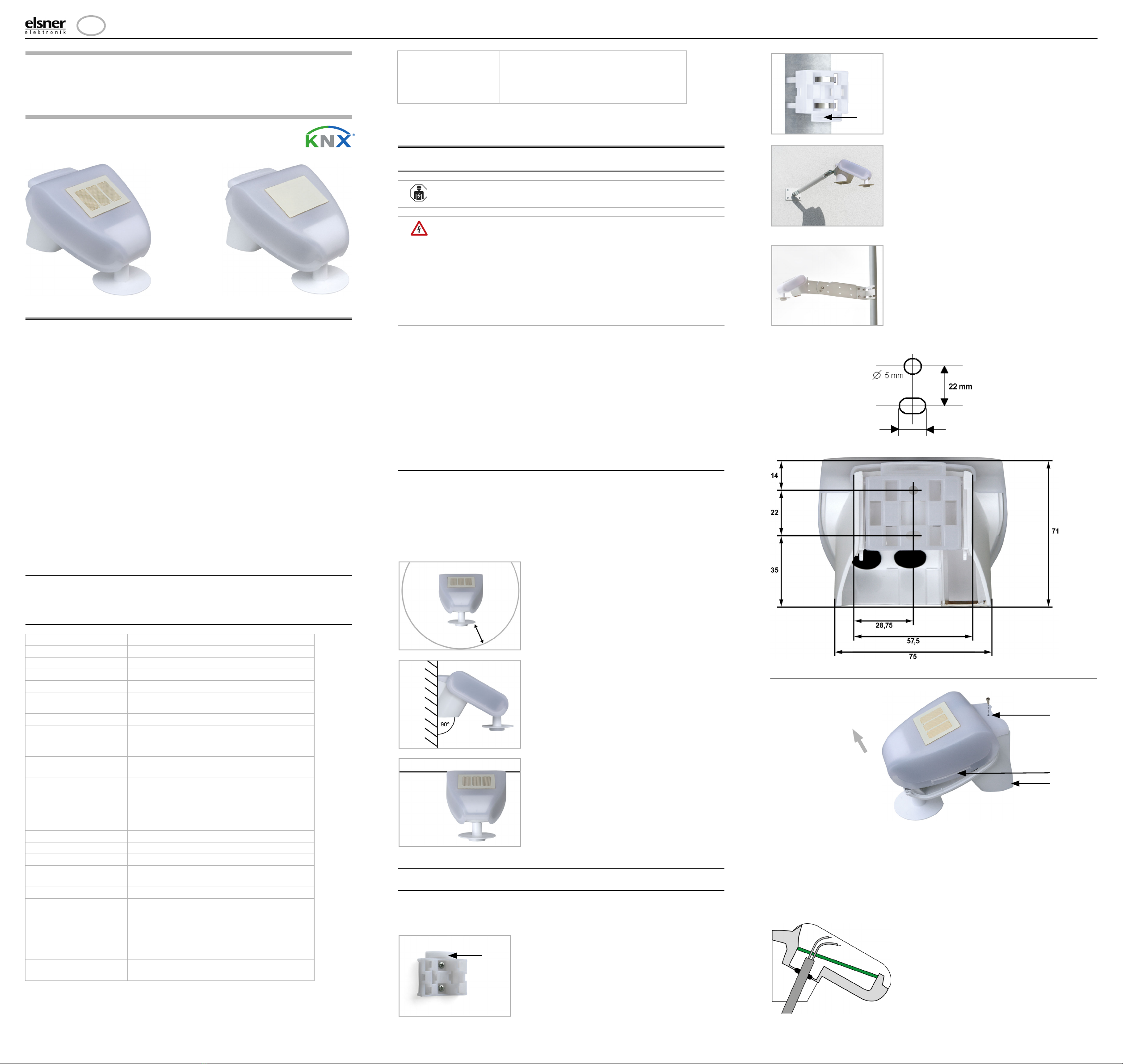
2.3.2. View of rear side and drill hole plan
2.3.3. Preparing the sensor
The sensor cover snaps in on the left and right along the bottom edge (see Fig.).
The cover of the 230V model is also screwed on top. Remove the cover. Proceed
carefully, so as not to pull off the wire connecting the PCB in the bottom part with
the cover (soldered cable connection in case of 230 V AC version, cable with plug
in case of 20...32 V DC version).
Lead the cable for the voltage supply and bus connection through the rubber seals
on the bottom of the device and connect Voltage L/N and Bus +/- to the terminals
provided.
Housing Plastic material
Colour White/translucent
Mounting On-wall
Degree of protection IP 44
Dimensions approx. 96 × 77 × 118 (W × H × D, mm)
Weight 230 V AC version approx. 240 g,
20...32 V DC version approx. 170 g
Ambient temperature Operation -30…+50°C, storage -30…+70°C
Operating voltage Available for 230 V AC or for 20...32 V DC
An appropriate power supply unit can be
obtained from Elsner Elektronik.
Cable cross-section Massive conductors of up to 1.5 mm² or con-
ductors with fine wires
Current 230 V AC version max. 20 mA,
20...32 V DC version:
max. 30 mA. max. 0,4 W.
residual ripple 10%
Data output KNX +/- bus terminal plug
Group addresses max. 254
Allocations max. 255
Communication objects 117
Measurement range
Wind
0...35 m/s
Resolution (wind) 0,1 m/s
Accuracy (wind) at ambient temperature -20…+50°C:
±22% of the measurement value when inci-
dent flow is from 45…315°
±15% of the measurement value when inci-
dent flow is from 90…270°
(Frontal incident flow corresponds to 180°)
Measurement range
brightness
0 lux … 150,000 lux
Resolution (brightness) 1 lux up to 300 lux
2 lux up to 1,000 lux
25 lux up to 150,000 lux
Accuracy (brightness) ±15% of the measurement value at 30 lux …
30,000 lux
Fig. 1
There must be at least 60 cm of space
below, to the sides and in front of the
sensor left from other elements (struc-
tures, construction parts, etc.).
60 cm
Fig. 2
The brightness/wind sensor must be
mounted on a vertical wall (or a pole).
Wall
or
pole
Fig. 3
The brightness/wind sensor must be
mounted in the horizontal transverse
direction (horizontally).
Horizontal
Fig. 4
When wall mounting: flat side on wall,
crescent-shaped collar upward.
Collar
Fig. 5
When pole mounting: curved side on po-
le, collar downward.
Collar
Fig. 6
Different mounting arms are available
from Elsner Elektronik as additional, op-
tional accessories for flexible installation
of the weather station on a wall, pole or
beam.
Example of the use of a mounting arm:
Due to flexible ball joints, the sensor can
be brought into ideal position.
Fig. 7
Example use of the hinge arm mounting:
Fitting to a pole with worm drive hose
clips
Slot hole 7,5 x 5 mm
Fig. 8 a+b
Drill hole plan
Dimensions of rear side
of housing with bra-
cket. Subject to change
for technical enhance-
ment.
Fig. 9
1 Screw-on cover (230V
device)
2 Cover snaps
3 Bottom part of housing
2
3
Unsnap cover
and remove upwards
1
Fig. 10
Remove the cable shielding under the
circuit board and only feed the con-
nector cables upwards through the
openings in the circuit board.
EN
Brightness and Wind Sensor KNX LW 2
Brightness and Wind Sensor KNX LW • Version: 04.11.2020 • Technical changes and errors excepted. • Elsner Elektronik GmbH • Sohlengrund 16 • 75395 Ostelsheim • Germany • www.elsner-elektronik.de • Technical Service: +49 (0) 7033 / 30945-250
2.3.4. PCB layout
230 V AC version
20...32 V DC version
2.3.5. Mounting the weather station
Close the housing by putting the cover back over the bottom part. The cover must
snap in on the left and right with a definite “click”.
DANGER!
There is a risk to life from the live voltage on a 230 V device!
• The cover must be screwed on in operation.
To remove it, the weather station can be simply pulled upwards out of the mount,
against the resistance of the fastening.
2.4. Notes on mounting and commissioning
Do not open the device if water (rain) might ingress: even some drops might da-
mage the electronic system.
Observe the correct connections. Incorrect connections may destroy the sensor or
connected electronic devices.
The measured wind value and thus all other wind switching outputs may only be
supplied 60 seconds after the supply voltage has been connected.
After the auxiliary voltage has been applied, the device will enter an initialisation
phase lasting a few seconds. During this phase no information can be received or
sent via the bus.
3. Addressing of the device at the bus
The device is supplied with the bus address 15.15.255. You can program another
address into the ETS by overwriting the 15.15.255 address or by teaching via the
programming key on the circuit board inside the housing.
DANGER!
Risk to life from live voltage (mains voltage)!
• With the 230V model, bus addressing via the programming key
should only be done by an accredited electrician.
• Do not touch any components on the circuit board while pressing
the key.
4. Maintenance
DANGER!
There is a risk to life from the live voltage (mains voltage)!
If you come into contact with live components in the device,
(e.g. caused also by a jet of water) there is the risk of an electric
shock with 230 V devices.
Risk of injury caused by components moved automatically!
The automatic control can start system components and place people
in danger (e.g. moving windows/awnings if a rain/wind alarm has
been triggered while cleaning).
• Always isolate the device from the mains for servicing and cleaning
(e. g. switch off or remove the fuse).
The device must regularly be checked for dirt twice a year and cleaned if necessary.
In case of severe dirt, the sensor may not work properly anymore.
ATTENTION
The device can be damaged if water penetrates the housing.
• Do not clean with high pressure cleaners or steam jets.
5. Disposal
After use, the device must be disposed of or recycled in accordance with the legal
regulations. Do not dispose of it with the household waste!
Fig. 11
1 Opening for the cable for
the voltage supply
2 Tension clamp for volta-
ge supply (230 V AC),
suitable for massive con-
ductors of up to 1.5 mm²
or conductors with fine
wires
3 Opening for bus cable
4 Slot for KNX clamp +/-
5 Programming pushbut-
ton for the teach-in of the
device
6 Programming LED
1
2
5
6
3 4
Fig. 12
1 Tension clamp for volta-
ge supply (20...32 V DC).
Massive conductors of
up to 1.5 mm² or conduc-
tors with fine wires. Ter-
minal configuration inde-
pendent from polarity (+/
- or -/+).
2 Opening for the cable for
the voltage supply and
for bus cable
3 Slot for KNX clamp +/-
4 Programming pushbut-
ton for the teach-in of the
device
5 Programming LED
12
4
5
3
Fig. 13
Make sure the cover and bottom part
are properly snapped together! This
picture is looking at the closed sensor
from underneath.
Fastening
Fig. 14
With the 230V model, screw the cover
on to the underpart, to prevent unaut-
horised or accidental opening.
Fig. 15
Push the housing from above into the
fastened mount. The bumps on the
mount must snap into the rails in the
housing.
Fig. 16
After installation, remove the protecti-
ve sticker on the wind sensor and the
"distance" sticker on the top of the co-
ver.

Other elsner elektronik Accessories manuals

elsner elektronik Vari KNX 3L-TH-D GPS User manual

elsner elektronik

elsner elektronik Vari KNX 3L-TH-D GPS User manual

elsner elektronik KNX L User manual

elsner elektronik

elsner elektronik KNX L User manual

elsner elektronik AQS/TH PF User manual

elsner elektronik

elsner elektronik AQS/TH PF User manual

elsner elektronik KNX T-B-UP User manual

elsner elektronik

elsner elektronik KNX T-B-UP User manual

elsner elektronik 30170 User manual

elsner elektronik

elsner elektronik 30170 User manual

elsner elektronik P04i-W User manual

elsner elektronik

elsner elektronik P04i-W User manual

elsner elektronik KNX RW sl User manual

elsner elektronik

elsner elektronik KNX RW sl User manual

elsner elektronik KNX VOC/TH-UP Touch User manual

elsner elektronik

elsner elektronik KNX VOC/TH-UP Touch User manual

elsner elektronik KNX VOC/TH-UP Touch CH User manual

elsner elektronik

elsner elektronik KNX VOC/TH-UP Touch CH User manual

elsner elektronik KNX LW sl User manual

elsner elektronik

elsner elektronik KNX LW sl User manual

elsner elektronik KNX T-L-Pr-UP Touch Guide

elsner elektronik

elsner elektronik KNX T-L-Pr-UP Touch Guide

elsner elektronik TH-UP basic User manual

elsner elektronik

elsner elektronik TH-UP basic User manual

elsner elektronik 20550 User manual

elsner elektronik

elsner elektronik 20550 User manual

elsner elektronik KNX TH-UP Touch User manual

elsner elektronik

elsner elektronik KNX TH-UP Touch User manual

elsner elektronik KNX AQS/TH-B-UP User manual

elsner elektronik

elsner elektronik KNX AQS/TH-B-UP User manual

elsner elektronik KNX R Guide

elsner elektronik

elsner elektronik KNX R Guide

elsner elektronik R 24 V User manual

elsner elektronik

elsner elektronik R 24 V User manual

elsner elektronik Vari KNX 3L-TH-D GPS Guide

elsner elektronik

elsner elektronik Vari KNX 3L-TH-D GPS Guide

elsner elektronik KNX W Series Guide

elsner elektronik

elsner elektronik KNX W Series Guide

elsner elektronik KNX B8-TH Guide

elsner elektronik

elsner elektronik KNX B8-TH Guide

elsner elektronik KNX RW User manual

elsner elektronik

elsner elektronik KNX RW User manual

elsner elektronik WGTH-UP User manual

elsner elektronik

elsner elektronik WGTH-UP User manual

elsner elektronik KNX R Guide

elsner elektronik

elsner elektronik KNX R Guide

elsner elektronik Sewi KNX L Guide

elsner elektronik

elsner elektronik Sewi KNX L Guide

Popular Accessories manuals by other brands

Kogan KAELBLFFSBA user guide

Kogan

Kogan KAELBLFFSBA user guide

Shure 27EU3222B instructions

Shure

Shure 27EU3222B instructions

Simpnic SiMP Plug Quick installation guide

Simpnic

Simpnic SiMP Plug Quick installation guide

SMART Camfire user guide

SMART

SMART Camfire user guide

Baumer UNDK 09U6914 quick start guide

Baumer

Baumer UNDK 09U6914 quick start guide

Flux's EPSILON manual

Flux's

Flux's EPSILON manual

LEGRAND 0 488 04 manual

LEGRAND

LEGRAND 0 488 04 manual

BRIGHT 017430 operating instructions

BRIGHT

BRIGHT 017430 operating instructions

Eurotronic 700209 quick start guide

Eurotronic

Eurotronic 700209 quick start guide

3BAYS LIFE GSA PRO quick start guide

3BAYS LIFE

3BAYS LIFE GSA PRO quick start guide

Sportcraft SODIS-215 SERIES Assembly instructions

Sportcraft

Sportcraft SODIS-215 SERIES Assembly instructions

Omron E2 ELITE brochure

Omron

Omron E2 ELITE brochure

Yale smart Living AC-PS-EU How Does it Work

Yale

Yale smart Living AC-PS-EU How Does it Work

SPALDING Backboard and Rim owner's manual

SPALDING

SPALDING Backboard and Rim owner's manual

Craftsman 358.792421 Operator's manual

Craftsman

Craftsman 358.792421 Operator's manual

IDEAL 58-N Series user guide

IDEAL

IDEAL 58-N Series user guide

MOTU 896 user guide

MOTU

MOTU 896 user guide

LeuchtenDirekt 995090 user manual

LeuchtenDirekt

LeuchtenDirekt 995090 user manual

manuals.online logo
manuals.online logoBrands
  • About & Mission
  • Contact us
  • Privacy Policy
  • Terms and Conditions

Copyright 2025 Manuals.Online. All Rights Reserved.