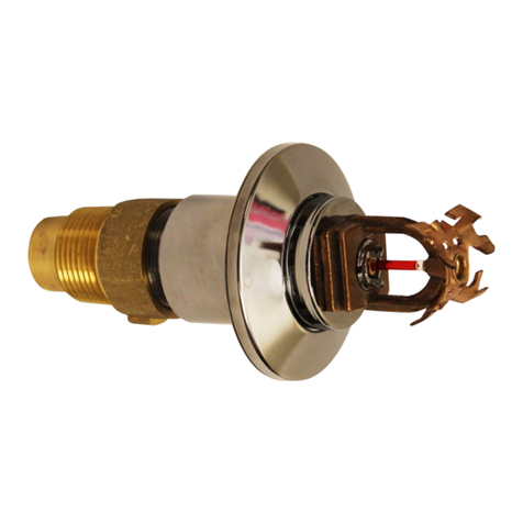
GEM AQUARIUS F993 User manual

FLUSH HORIZ. SIDEWALL SPRINKLERS, RES/QR-EC/EC
MODEL F993 AQUARIUS®, 5.6 K-FACTOR
GENERAL DESCRIPTION
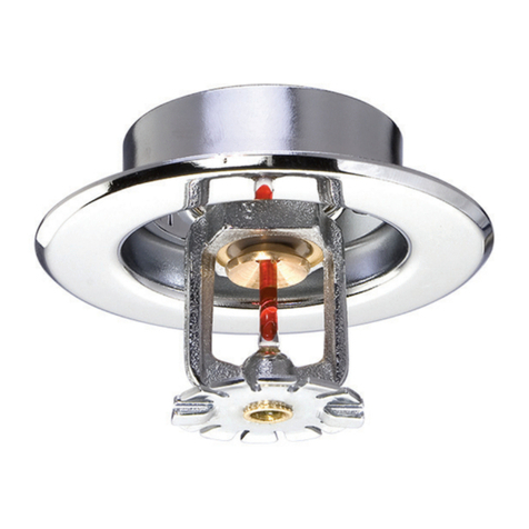
The 5.6 K-Factor, Model F993 Aquar-
ius RES/QR-EC/EC Horizontal Side-
wall Sprinklers (Ref. Figure A) are
automatic sprinklers of the fusible sol-
der type. They are low profile, flush
mounting sprinklers which are in-
tended to be used in
•wet pipe residential sprinkler sys-
tems for one- and two-family dwell-
ings and mobile homes per NFPA
13D,
•wet pipe residential sprinkler sys-
tems for residential occupancies up
to four stories in height per NFPA
13R,
•wet pipe sprinkler systems for the
residential portions of any occu-
pancy per NFPA 13,
•light hazard, quick response — ex-
tended coverage (QR-EC) sprinkler
system applications per NFPA 13,
and
•light hazard, extended coverage
(EC) sprinkler system applications
per NFPA 13.
Small and attractive, the F993 Sprin-
klers are installed with a Push-on Es-
cutcheon Plate and feature a smooth,
low profile, flush-style design with an
aesthetically pleasing appearance that
blends in with all types of surround-
ings. They are designed for installation
along a wall or lintel and just beneath
a smooth and level ceiling. Horizontal
sidewall sprinklers are generally used
in lieu of pendent or upright sprinklers
because of aesthetic, building con-
struction, or installation economy con-
siderations.
The 1/4 inch adjustment provided by
the Push-on Escutcheon Plate and the
additional 1/4 inch of adjustment that
can be obtained by use of the Exten-
sion reduces the accuracy to which the
sprinklers must be positioned. The 3
inch outside diameter of the Push-on
Plate also contributes to the ease of
installation by covering offset clear-
ance holes.
The F993 Sprinklers have been de-
signed to operate with a particular fus-
ible element temperature rating and
heat sensitivity characteristic, as well
as to discharge water in a specific pat-
tern and quantity per square foot rela-
tionship. The combination of the per-
formance characteristics which are
associated with the F993 Sprinklers
have been proven to help in the control
of residential type fires and, therefore,
to improve the chance for occupants to
escape or be evacuated.
FIGURE A
5.6 K-FACTOR MODEL F993 AQUARIUS (SIN G8993) RES/QR-EC/EC
HORIZONTAL SIDEWALL SPRINKLERS
NOTE:
The Fusible Element Assembly (consisting of Components 5 through 14)
falls out of he Body upon sprinkler operation.
Printed in U.S.A. 7-02 TD591
COMPONENTS:
1 - Dust Cap
2 - Arms
3 - Body
4 - Gasketed
Button-
Deflector
5 - Retaining
Ring
6-Heat
Collectors
7 - Inner Loading
Plate
8 - Outer Loading
Plate
9 - Loading
Screw
10 - Solder Element
11 - Disc Spring
12 - Insulating
Washer
13 - Tamper
Resistant
Plug
14 - Spacer
PUSH-ON PLATE
WITH EXTENSION
PUSH-ON
PLATE
TYCO FIRE PRODUCTS, 7071 S. 13th Street, Suite 103 Oak Creek, WI 53154 — www.gemsprinkler.com
Customer Service/Sales: Tel: (800) 558-5236 / Fax: (800) 877-1295
Technical Services: Tel: (800) 381-9312 / Fax: (800) 791-5500
SPRINKLERS FOR REPLACEMENT USE ONLY IN EXISTING SPRINKLER SYSTEMS
OBSOLETE

Fire sprinkler systems are not a substi-
tute for intelligent fire safety aware-
ness or construction materials and
practices required by building codes.
APPROVALS AND STANDARDS
The 5.6 K-Factor, Model F993 Aquar-
ius RES/QR-EC/EC Horizontal Side-
wall Sprinklers are listed by Underwrit-
ers Laboratories Inc. and
Underwriters’ Laboratories of Canada.
The listings only apply to the service
conditions indicated in the General
Technical Data and Installation/Usage
sections.
The Model F993 Aquarius RES/QR-
EC/EC Horizontal Sidewall Sprinklers
are approved by the Scientific Serv-
ices Laboratory (Australia).
The Model F993 Aquarius RES/QR-
EC/EC Horizontal Sidewall Sprinklers
areapprovedbytheNewYorkCity
Board of Standards and Appeals un-
der Calendar Number 334-79-SA.
Any questions concerning an interpre-
tation of NFPA 13, 13D, or 13R sprin-
kler system design/installation stand-
ards, as well as requests for system
design/installation standards not pres-
ently covered by NFPA 13, 13D, or
13R, should be addressed to the:
Secretary, Standards Council
National Fire Protection Association
Batterymarch Park
Quincy, MA 02269
WARNINGS
The Model F993 Aquarius
RES/QR-EC/EC Horizontal Side-
wall Sprinklers described herein
must be installed and maintained
in compliance with this docu-
ment, as well as with the applica-
ble standards of the National Fire
Protection Association, in addi-
tion to the standards of any other
authorities having jurisdiction.
Failure to do so may impair the
integrity of these devices.
Because of the above cited stipu-
lations and the varied nature of
residential type architecture,
there will be some compartment
designs which cannot be fully
sprinklered in accordance with
the recommendations of NFPA 13,
13D, or 13R. In the event of this
condition, consult the authorities
having jurisdiction for guidance.
It is the responsibility of an in-
stalling contractor to provide a
copy of this document to the
owner or his representative and,
in turn, it is the obligation of the
owner to provide a copy of this
document to a succeeding owner.
The owner is responsible for
maintaining their fire protection
system and devices in proper op-
erating condition. The installing
contractor or sprinkler manufac-
turer should be contacted relative
to any questions.
GENERAL TECHNICAL DATA
Sprinkler Assemblies:
The 5.6 K-Factor, Model F993 Aquar-
ius RES/QR-EC/EC Horizontal Side-
wall Sprinklers are available in a
160°F/71°C temperature rating and
they are rated for use at a maximum
service pressure of 175 psi. They are
available with a chrome, white, or
bright brass finish. Escutcheon Plates
are available with various finishes and
are ordered separately, as indicated in
the following sub-section.
The F993 is shipped with a plastic Pro-
tective Cap covering the outside of the
Fusible Element and the outer portion
of the Body. The Protective Cap can
be left in position while the Sprinkler is
being installed and then it is slid off
once the wall installation is complete
and the sprinkler system is ready to be
put into service.
The nominal flow “Q” in GPM (LPM) is
determined by the following formula:
Q=K(p
1/2)
where the nominal sprinkler discharge
coefficient “K” equals 5.6 (80,6); and
“p” equals the residual pressure in psi
(bar).
The Body is bronze per ASTM B584
(C83600 or C84400) and the Dust Cap
is polyolefin. The Heat Collectors are
copper per ASTM B152 (C11000) and
the Inner & Outer Loading Plates and
Spacer are brass per ASTM B16
(C36000) or ASTM B140 (C31400 or
C31600). The Loading Screw and two
Arms are Type 302 stainless steel per
ASTM A276 or Type 303 per ASTM
A582. The Disc Spring is a chrome
plated high strength carbon steel and
the Retaining Ring is titanium per
ASTM B348 (Grade 5). The Gasketed
Button-Deflector consists of brass but-
ton per ASTM B16 (C36000), brass
deflector per ASTM B36 (C22000),
and a Teflon
gasket.
Escutcheon Plates:
The following are the two types of es-
cutcheon plates that may be used with
the F993 Aquarius Sprinkler:
•Push-on Escutcheon Plate
•Push-on Escutcheon Plate with Ex-
tension
Figures C and D illustrate typical in-
stallations of an F993 using a Push-on
Escutcheon Plate and using a Push-on
Plate with Extension. The Push-on Es-
cutcheon Plate provides a total of 1/4
inch of horizontal adjustment and it is
installed by simply slipping it over the
F993 Body; however, when it is used
in conjunction with the Extension, an
additional 1/4 inch of adjustment can
be obtained for a total of 1/2 inch of
horizontal adjustment.
When using the Push-on Plate with
Extension, the installer simply deter-
mines the approximate distance from
the wall mounting surface to the out-
Dim. Inches MM
A - Nom. 1-1/16 27.0
B - 2-1/4 57.2
C- 3 76.2
D - Min. 7/8 22.2
D - Nom. 1 25.4
D - Max. 1-1/8 28.6
FIGURE C
PUSH-ON ESCUTCHEON
PLATE
Dim. Inches MM
A - Nom. 15/16 23.8
B - 2-1/4 57.2
C - 3-1/8 79.4
D - Min. 7/8 22.2
D - Nom. 1-1/8 28.6
D - Max. 1-3/8 34.9
FIGURE D
PUSH-ON ESCUTCHEON
PLATE WITH EXTENSION
DuPont Registered Trademark
—2—
OBSOLETE

side of the Heat Collector. The Exten-
sion is used when this distance (Ref.
“D” in Figure D) is greater than 1-1/8
inches and, the Extension is discarded
for distances of 1-1/8 inches or less.
The Push-on Escutcheon Plate and
Extension are formed from low carbon
sheet steel and they are available with
a chrome or white finish. Also, a color
finish other than white can be pro-
vided.
NOTE
The Push-on Escutcheon Plates
shown in Figures C and D can
NOT be used to hold the F993 in
position. The F993 must be se-
cured in position by firmly fasten-
ing the sprinkler system piping to
the dwelling structure. If the F993
is not properly secured in posi-
tion, reaction forces resulting
from sprinkler operation could
alter its orientation and water
distribution pattern.
QR-EC&EC
INSTALLATION/USAGE CRITERIA
When used in QR-EC (quick response
— extended coverage) or EC (ex-
tended coverage) applications, Model
F993 Aquarius RES/QR-EC/EC Hori-
zontal Sidewall Sprinklers must only
be installed and utilized in Light Haz-
ard Occupancies, under smooth and
level ceilings and in accordance with
the criteria given in Table A.
NOTES
For coverage area dimensions
less than those indicated in Table
A, it is necessary to use the mini-
mum required flow for the highest
width (W) and length (L) for
which installation criteria are
stated.
The F993 Sprinklers must NOT be
used with beams, joists, or ducts
located within the sprinkler cov-
erage area. They may be located
along the boundaries separating
adjacent sprinkler coverage ar-
eas.
RESIDENTIAL
INSTALLATION/USAGE CRITERIA
When used in residential applications,
the Model F993 Aquarius RES/QR-
EC/EC Horizontal Sidewall Sprinklers
must only be installed and utilized in
accordance with the following de-
scribed criteria which are provided by
the manufacturer.
These restrictions relate to
•the general service conditions nec-
essary to sprinkler performance and
integrity,
•the minimum amount of water which
must be discharged from an operat-
ing sprinkler,
•the maximum area which can be
covered by the spray from an oper-
ating sprinkler,
•installation requirements necessary
to the proper operational sensitivity
of the sprinklers,
•preventing the wetting (i.e., cold sol-
dering) of the Fusible Element As-
sembly of a non-operated sprinkler,
which is adjacent to one which has
operated, and
•preventing the weakening followed
by the possible release of a sprin-
kler’s Fusible Element Assembly,
due to exposure to heat sources
other than abnormal fire.
NOTES
1. Residential Fire Sprinkler Sys-
tems should only be designed
and installed by those compe-
tent and completely familiar
with automatic sprinkler sys-
tem design, installation proce-
dures, and techniques.
2. Several criteria may apply to
the installation and usage of
each sprinkler. Consequently,
it is recommended that the
NFPA 13D/13R NFPA 13D/13R NFPA 13
MINIMUM MINIMUM EC
SINGLE HEAD(e) MULTIPLE HEAD(e) MINIMUM
W x L FLOW FLOW FLOW A B
FT x FT GPM (psi)(d) GPM (psi)(d) GPM (psi)(d) INCHES FEET
RES(a) 12 x 12 22 (15.4)(e) 15.5 (7.7) — 4 to 6(f) 6
RES(a) 14 x 14 30 (28.7)(e) 21(14.1) — 4 to 6(f) 7
QR-EC(b) 14 x 16 — — 26 (21.6) 4 to 6(f) 7
EC(c) 14 x 18 — — 36 (41.3) 4 to 6(f) 7
NOTES:
(a) Wet pipe fire sprinkler systems in the residential portions of any occupancy per NFPA
13, in one- and two- family dwellings and mobile homes per NFPA 13D, or residential
occupancies per NFPA 13R.
(b) For use in QR-EC and EC Light Hazard Occupancy automatic sprinkler system applica-
tions per NFPA 13.
(c) For use in EC Light Hazard Occupancy automatic sprinkler system applications per NFPA
13.
(d) Requirement is based on minimum flow in GPM from each sprinkler. The indicated
residual pressures are based on the nominal K-factor.
(e) Refer to Hydraulic Design Criteria under Residential Installation/Usage Criteria Section
for details.
(f) To meet this requirement, the centerline of the waterway (Ref. Fig. A) must be installed
between 4-5/8 and 6-5/8 inches below the ceiling.
TABLE A
HYDRAULIC DESIGN CRITERIA FOR
MODEL F993 AQUARIUS RES/QR-EC/EC
HORIZONTAL SIDEWALL SPRINKLERS
—3—
OBSOLETE

sprinkler system designer re-
view and develop a working un-
derstanding of thecomplete list
of criteria, prior to initiating
the design of the sprinkler sys-
tem.
3. Questions concerning sprink-
ler installation and usage cri-
teria, which are not covered by
the following instructions,
should be mailed to the atten-
tion of the Technical Data De-
partment. Include sketches
and technical details, as ap-
propriate.
4. In some instances, the require-
mentsofthisdocumentmay
concern specifications which
are more stringent and which
take precedence over those
specified in NFPA 13, NFPA
13D,NFPA13R,orbythe
authority having jurisdiction.
General Service Conditions
The F993 Sprinklers must only be util-
ized
1. in wet pipe automatic sprinkler sys-
tems,
2. within residential portions of any oc-
cupancy per NFPA 13, within resi-
dential “Dwelling Units” per NFPA
13D, or within residential occupan-
cies per NFPA 13R.
3. at a maximum service pressure of
175 psi,
4. at a maximum ambient temperature
of 100F/38C,
5. with all interconnecting system pip-
ing, as well as sprinklers maintained
at a minimum temperature of
40F/4C, and
6. with water supplies which are sub-
stantially free of contaminants and
particles of a size greater than 1/8
inch.
Hydraulic Design Criteria
The minimum required flow rates for
residential applications are given in
Table A as a function of the maximum
allowable coverage areas. The NFPA
13D/13R single sprinkler flow rate is
the minimum required discharge from
the most hydraulically demanding sin-
gle sprinkler and the NFPA 13D/13R
multiple sprinkler flow rate is the mini-
mum required discharge from each of
the total number of “design sprinklers”
as specified in NFPA 13D or 13R.
TIA 99-1 (Tentative Interim Amend-
ment) with an effective date of May 22,
2000 states that the minimum re-
quired discharge from each of the “de-
sign sprinklers” for systems designed
to NFPA 13 must be calculated based
on delivering a minimum design den-
sity of 0.1 gpm/sq. ft. for each of the
listed coverage areas shown in Table
A. Consult with the Authority Having
Jurisdiction regarding the application
of this TIA to the currently adopted
NFPA 13.
NOTE
The number of sprinklers within
each compartment (as defined by
NFPA 13, 13D, or 13R), must be as
few as possible. Do NOT use more
sprinklers than necessary to
cover a particular space.
Spray Coverage Criteria
Each F993 Sprinkler must only be
used in accordance with one of the
designated width by length (W x L)
coverage criteria specified in Table A.
Ceiling mounted obstructions such as
heating or air conditioning diffusers,
overhangs, and light fixtures must be
located above an elevation, as shown
in Figure E, where they will not inter-
fere with the proper distribution of
water by the sprinkler.
The F993 Sprinklers must NOT be lo-
cated
a. along wall overhangs or soffits,
b. along a wall/partition having a re-
cessed range oven, countertop, or
alcove,
c. along a wall/partition having an ad-
joining wood or coal burning stove,
or
d. along a wall/partition containing a
fireplace or wall oven.
NOTE
The spray from the F993 is distrib-
uted radially outward from the
sprinkler deflector. Sprinklers
must be located such that there
will NOT be any blind spaces
shielded from spray by partitions
or a portion of the dwelling struc-
ture.
Operational Sensitivity Criteria
The F993 Sprinklers must only be in-
stalled
1. beneath level ceilings,
2. beneath solid ceilings having a
smooth or textured surface,
3. flush mounted, as illustrated in Fig-
ure C or D, with a wall or face of a
lintel,
4. with a centerline of sprinkler water-
way to ceiling distance of between
4–5/8 and 6–5/8 inches (Ref. Table
A), and
5. at least 4 inches away from an inside
or outside corner.
The F993 Sprinklers must NOT be
used
a. beneath wall overhangs or soffits,
b. above or below open-gridded type
suspended ceilings, or
c. with beams, joists, or ducts located
within the sprinkler coverage areas.
NOTE
Beams, joists, or ducts may be lo-
cated with their centerlines along
the boundaries separating adja-
cent sprinkler coverage areas.
It is recommended that as part of the
sprinkler system design, the designer
review the dwelling plans and, where
appropriate, advise the owner or his
representative as to the following.
I. Lintels of at least 3 inches in height
and preferably 8 inches should be
used over all passageways from one
space to another, in order to reduce
the possibility of sprinkler operations
outside the fire area.
II. Beams of at least 3 inches in height
should be used to border each of 3
or more adjoining areas of F993
sprinkler coverage (within the same
compartment), in order to decrease
the time to first sprinkler operation as
well as to reduce the possibility of
multiple sprinkler operations.
Cold Soldering Criteria
With reference to Table A, the F993
Sprinklers must be located such that
1. the minimum lateral distance “C” be-
tween adjacent sprinklers is 8 ft.,
and
2. the minimum distance “D” between
sprinklers located opposite or with
their waterway centerlines at 90 de-
grees to each other is 14 ft., except
where a portion of the dwelling struc-
ture or a partition will shield the spray
of one sprinkler from the other.
Heat Source Criteria
Refer to NFPA 13D or NFPA 13R for
the requirements relating to prevent-
ing the weakening followed by the pos-
sible release of an F993 Sprinkler Fus-
ible Element Assembly, due to
exposure to heat sources other than
abnormal fire.
—4—
OBSOLETE

INSTALLATION
NOTE
Residential Fire Sprinkler Sys-
tems should only be designed and
installed by those competent and
completely familiar with auto-
matic sprinkler system design, in-
stallation procedures, and tech-
niques.
The Model F993 Aquarius RES/QR-
EC/EC Horizontal Sidewall Sprinklers
must be installed in accordance with
the following instructions.
1. The Sprinkler must only be installed
in the sidewall, flush position with the
centerline of the waterway horizon-
tal and perpendicular to the mount-
ing surface.
NOTE
It is recommended that a spirit
level be used to level the sprin-
kler fitting as shown in Figure F
and that a square be used to
check perpendicularity of the
waterway centerline to the
mounting surface.
2. When using the Push-on Escutch-
eon Plate shown in Figure C, the
pipe connected to the sprinkler fitting
should be cut so that the “A” dimen-
sion is between 1 and 1-1/8 inches.
When using the Push-on Escutch-
eon Plate with Extension shown in
Figure D, the pipe connected to the
sprinkler fitting should be cut so that
the “A” dimension is between 13/16
and 1-1/16 inches. In either case,
the remaining portion of the adjust-
ment can be used to help compen-
sate for the possible manufacturing
variations in the make-in of the
Sprinklers and the take-out of the
fittings (as permitted by ANSI
B1.20.1).
NOTE
The Push-on Escutcheon Plates
shown in Figures C and D can
NOTbeusedtoholdtheSprin-
kler in position. The Sprinkler
must be secured in position by
firmly fastening the sprinkler
system piping to the dwelling
structure. If the Sprinkler is not
properly secured in position, re-
action forces resulting from
sprinkler operation could alter
its orientation and water distri-
bution pattern.
3. With pipe thread sealant applied to
the pipe threads, hand tighten the
Sprinkler with the attached Protec-
tive Cap (as shipped), into the sprin-
kler fitting.
4. Using the Model F873 Sprinkler
Wrench shown in Figure G, tighten
the Sprinkler into the fitting. The
word “TOP” on the Deflector Hat
must face upwards towards the ceil-
ing.
The Wrench is slipped over the Pro-
tective Cap and can be mounted to
a 1/2 inch socket drive ratchet. A
radial force of 10 to 18 lbs. applied
to a typical 9 inch long ratchet handle
will exert the 7 to 14 ft.lbs. of torque
required for a leak tight sprinkler
joint.
NOTES
It is recommended that a spirit
level be used to level the Deflec-
tor Hat, as shown in Figure F.
A maximum of 21 ft.lbs. of
torque is to be used to install the
sprinkler. Higher levels of
torque may distort the sprinkler
orifice seat with consequent
leakage.
5. Do not remove the Protective Cap at
this time. The Protective Cap is in-
tended to help protect the sprinkler
until the wall finish is complete and
the sprinkler system is ready to be
put into service.
NOTE
Failure to use the Protective
Cap, while the wall installation
is being completed, can result in
theaccidentaldamageorpaint-
ing of a sprinkler. Damaged or
painted sprinklers must be re-
placed.
6. After the wall finishing is complete
and the sprinkler system is ready to
be put into service, slide off the Pro-
tective Cap.
NOTE
FailuretoremovetheProtective
NOTES:
1. For a given position within the coverage area, ceiling mounted obstructions must not hang
below the elevation dimension given in the graph.
2. Elevation dimensions are with respect to the top of the Deflector Hat (ref. Fig. A), where
positive (+) dimensions are above the Deflector Hat and negative (-) dimensions are below.
(Reference: the Deflector Hat is 5/8" above the sprinkler centerline of waterway.)
FIGURE E
ALLOWABLE ELEVATION FOR CEILING MOUNTED OBSTRUCTIONS
SUCH AS HEATING OR AIR CONDITIONING DIFFUSERS, OVERHANGS,
AND LIGHT FIXTURES
—5—
FIGURE F
LEVELING OF
SPRINKLER FITTING
AND DEFLECTOR
FIGURE G
MODEL F873
SPRINKLER WRENCH
OBSOLETE

Cap will prevent proper opera-
tion of the Sprinkler.
7. When using the Push-on Escutch-
eon Plate alone, align the two slots
on the inside edge of the Push-on
Escutcheon Plate with the Wrench
Lugs on the Sprinkler Body and then
push the Escutcheon Plate over the
Body of the Sprinkler until its outside
edge comes in contact with the
mounting surface.
When using the Push-on Plate with
Extension, first determine the dis-
tance from the wall mounting sur-
face to the outside of the Heat Col-
lector. If the dimension is 1-1/8
inches or less, discard the Extension
and proceed to install the Push-on
Plate as indicated above. If the di-
mension is greater than 1-1/8
inches, assemble the Extension to
the Push-on Plate and then proceed
to install the assembly as indicated
above.
NOTE
Do not attempt to make-up for
insufficient adjustment in an
Escutcheon Plate by under- or
over-tightening the Sprinkler.
Readjust the position of the
sprinkler fitting to suit.
CARE AND MAINTENANCE
The Model F993 Sprinklers must be
maintained and serviced in accord-
ance with the following instructions:
NOTES
Absence of an Escutcheon Plate
may delay the time to sprinkler
operation in a fire situation.
Before closing a fire protection
system main control valve for
maintenance work on the fire pro-
tection system which it controls,
permission to shut down the af-
fected fire protection systems
must be obtained from the proper
authorities and all personnel who
maybeaffectedbythisaction
must be notified.
Particular care to prevent over-
heating must be exercised when
storing sprinklers in cars, trucks,
trains, or other vehicles on warm,
bright sunny days.
Sprinklers which are found to be leak-
ing or exhibiting visible signs of cor-
rosoin must be replaced.
Automatic sprinklers must never be
shipped or stored where their tempera-
ture will exceed 100°F/38°C and they
must never be painted, plated, coated,
or otherwise altered after leaving the
factory. Modified or over-heated sprin-
klers must be replaced.
Care must be exercised to avoid dam-
age to the sprinklers - before, during,
and after installation. Sprinklers dam-
aged by dropping, striking, wrench
twist/slippage, or the like, must be re-
placed.
The owner is responsible for the in-
spection, testing, and maintenance of
their fire protection system and de-
vices in compliance with this docu-
ment, as well as with the applicable
standards of the National Fire Protec-
tion Association (e.g., NFPA 25), in
addition to the standards of any other
authorities having jurisdiction. The in-
stalling contractor or sprinkler manu-
facturer should be contacted relative
to any questions.
It is recommended that automatic
sprinkler systems be inspected,
tested, and maintained by a qualified
Inspection Service.
The F993 Sprinklers must only be re-
placed with pendent sprinklers which
are listed for residential fire protection
service and which have the same
nominal K-factor, the same coverage
area, and the same or lower flow rat-
ings (as indicated under “Hydraulic
Design Criteria”).
All residential sprinklers installed
within a compartment (as defined by
the NFPA) must have the same heat
response thermal characteristic, and
their temperature ratings are to be
within 10°F of each other.
NOTES
Wet pipe sprinkler systems must
be maintained at a minimum tem-
perature of 40F/4C. Exposure to
freezing temperatures can result
in bursting of the pipe and/or
sprinkler.
Do NOT enclose sprinklers within
drapes, curtains, or valances.
Do NOT hang anything from the
sprinklers.
Automatic sprinklers are NOT to
be tested with a heat source. Op-
eration of the heat responsive
element (Bulb) can result.
Do NOT cleanse the sprinklers
with soap and water, detergents,
ammonia, cleaning fluids, or
other chemicals. Remove dust,
lint, cobwebs, cocoons, insects,
andlarvaebygentlybrushing
with a feather duster or gently
vacuuming with a soft bristle (i.e.,
dusting) brush attachment.
The minimum vertical clearance
between the tops of free standing
partitions, room dividers, cab-
inets, storage racks, stock piles,
etc., and the sprinkler deflector is
NOT to be less than the clearance
given below.
Horizontal Distance Vertical
from Sprinkler Clearance
to Item, ft. In.
Morethan9 ....... 40
From6to9........ 32
Between 3 and 6 . . . . . 26
3orLess ......... 18
Exercise suitable safety precau-
tions in the use and storage of
highly flammable and potentially
explosive materials. The rapid
rate of fire development and
spread which can be caused by
such materials can reduce the
ability of the sprinkler system to
aidinthecontrolofafirein
which they are involved.
—6—
OBSOLETE

LIMITED WARRANTY
Products manufactured by Tyco Fire
Products are warranted solely to the
original Buyer for ten (10) years
against defects in material and work-
manship when paid for and properly
installed and maintained under normal
use and service. This warranty will ex-
pire ten (10) years from date of ship-
ment by Tyco Fire Products. No war-
rantyisgivenforproductsor
components manufactured by compa-
nies not affiliated by ownership with
Tyco Fire Products or for products and
components which have been subject
to misuse, improper installation, corro-
sion, or which have not been installed,
maintained, modified or repaired in ac-
cordance with applicable Standards of
the National Fire Protection Associa-
tion, and/or the standards of any other
Authorities Having Jurisdiction. Mate-
rials found by Tyco Fire Products to be
defective shall be either repaired or
replaced, at Tyco Fire Products’ sole
option. Tyco Fire Products neither as-
sumes, nor authorizes any person to
assume for it, any other obligation in
connection with the sale of products or
parts of products. Tyco Fire Products
shall not be responsible for sprinkler
system design errors or inaccurate or
incomplete information supplied by
Buyer or Buyer’s representatives.
IN NO EVENT SHALL TYCO FIRE
PRODUCTS BE LIABLE, IN CON-
TRACT, TORT, STRICT LIABILITY
OR UNDER ANY OTHER LEGAL
THEORY, FOR INCIDENTAL, INDI-
RECT, SPECIAL OR CONSEQUEN-
TIAL DAMAGES, INCLUDING BUT
NOT LIMITED TO LABOR CHARGES,
REGARDLESS OF WHETHER TYCO
FIRE PRODUCTS WAS INFORMED
ABOUT THE POSSIBILITY OF SUCH
DAMAGES, AND IN NO EVENT
SHALL TYCO FIRE PRODUCTS’ LI-
ABILITY EXCEED AN AMOUNT
EQUAL TO THE SALES PRICE.
THE FOREGOING WARRANTY IS
MADE IN LIEU OF ANY AND ALL
OTHER WARRANTIES EXPRESS
OR IMPLIED, INCLUDING WARRAN-
TIES OF MERCHANTABILITY AND
FITNESS FOR A PARTICULAR PUR-
POSE.
REMODELING
When remodeling such as by adding
false beams or light fixtures or chang-
ing the location of compartment walls,
first verify that the new construction
will not violate the installation require-
ments stated under WARNINGS. Alter
the new construction and/or the sprin-
kler system to suit the requirements of
this document.
ORDERING PROCEDURE
Orders for the Model F993 Aquarius
RES/QR-EC/EC Horizontal Sidewall
Sprinklers, Push-on Escutcheon
Plates, Push-on Escutcheon Plates
with Extensions, and the Sprinkler
Wrench must include the description
and Product Symbol Number (PSN)
where applicable.
Contact your local distributor for avail-
ability.
Sprinkler Assembly:
Specify: Model F993 Aquarius
RES/QR-EC/EC Horizontal Sidewall
Sprinkler with (specify type) finish,
PSN (specify).
Chrome Plated Finish
160°F/71°C . . . . . . . . . . . . . . PSN 58-993-9-160
White Coated Finish
160°F/71°C . . . . . . . . . . . . . . PSN 58-993-4-160
Bright Brass Plated Finish
160°F/71°C . . . . . . . . . . . . . . PSN 58-993-2-160
NOTES
The Escutcheon Plate for the F993
Sprinkler and the Sprinkler
Wrench must be ordered sepa-
rately.
Product Symbol Numbers are not
specified when ordering Push-on
Escutcheon Plates with a color
other than white. It is suggested
that a color chip be provided
when ordering a special color.
Otherwise, responsibility for du-
plication of the desired color
coated finish cannot be accepted.
Push-on Escutcheon Plates:
Specify: (Specify type) finish Push-on
Escutcheon Plate for Aquarius Sprin-
kler, PSN (specify).
White coated finish . . . . . . . . PSN 56-991-0-003
Chrome plated finish . . . . . . . PSN 56-991-9-003
Push-on Escutcheon Plates with
Extension:
Specify: (Specify type) finish Push-on
Escutcheon Plate with Extension for
Aquarius Sprinkler, PSN (specify).
White coated finish . . . . . . . . PSN 56-991-0-013
Chrome plated finish . . . . . . . PSN 56-991-9-013
Replacement Extension:
Specify: (Specify type) finish Exten-
sion for Aquarius Sprinkler, PSN
(specify).
White coated finish . . . . . . . . PSN 91-991-0-101
Chrome plated finish . . . . . . . PSN 91-991-9-101
Sprinkler Wrench:
Specify: Model F873 Sprinkler
Wrench, PSN 56-873-1-001.
PATENTS
The following patents are applicable to
the Model F993 Aquarius RES/QR-
EC/EC Horizontal Sidewall Sprinklers:
COUNTRY............ PATENTNO.
U.S.A. ................ 4,618,002
UnitedKingdom........... 2,155,328
WEIGHT
The nominal weight of the Model F993
Aquarius RES/QR-EC/EC Horizontal
Sidewall Sprinkler (with Protective
Cap) is 4.2 ounces, the weight of the
Push-on Escutcheon Plate is 0.6
ounces, and the weight of the Push-on
Escutcheon Plate with Extension is 1.4
ounces.
—7—
OBSOLETE

OBSOLETE
Table of contents
Other GEM Irrigation System manuals

