8
SPARE PART LIST
LEGEND Abbreviation explanation:
(EU) =European Version (230Vac)
(US) =U.S. Version (115Vac)
(I) =Italian Version
(F) =French Version
(D) =German Version
(UK) =English Version
CODE DESCRIPTION
Accessories of Rp700 Packing
271389 Owner’s Manual (UK-I-F-D)
130297 10A-3P 2.5Mt Black Mains Cable (EU)
130283 10A-3P 2.5Mt Black Mains Cable (US)
970461 Rosewood Bench
MDL265001 * Black Seat for Bench
MDL265000 * Rosewood Leg for Bench
MDL525001 * Fixing Screw Kit
Stand
MDL715001 Rosewood Stand Right Leg Assembly
MDL715002 Rosewood Stand Left Leg Assembly
MDL665007 Black Painted Crossbar Angular Fixing
MDL665006 Black Painted Stand Rear Angular Fixing
MDL345072 Adjustable Foot with M6x10 Scew
MDL120016 Wl 3,5x15tc Black Zinc Plated Screw
MDL120006 M6x55 tcp Nicheled Plated Special Screw
120681 M6x13 Threaded Barrel Nut for Wooden
MDL715000 Rosewood Stand Pedal Crossbar Assembly
MDL725005 3 Pedals Brass Group Assembly
MDL265002 Rosewood Stand Pedal Crossbar (Without Pedal Group)
120059 M4x25tc Black Zinc Plated Screw
MDL345071 Adjustable Foot with M8x24 Screw
MDL345070 Black Knob with M6x23 Screw
MDL340116 Adhesive Black Clamp for Pedals Cable
MDL265003 Rosewood Stand Rear Panel
MDL120001 M6x40 TCP Nicheled Plated Special Screw
MDL525000 Fixing Screw Kit
Cabinet Assembly
MDL715005 Rosewood Wooden Cabinet Assembly
MDL665011 * Brown Painted Front Panel W/Silk
220120 * 6” Full-range 20W 8E Speaker
MDL665010 * Black Painted Speakers Protection Grid
MDL655097 * Brown Silkscreened Right Cheek Block
MDL345073 * Black Rack With Guide (Right)
MDL345078 * Black Rack With Guide (Left)
MDL265013 * Rosewood Music Holder
MDL265012 * Cabinet Bottom Base
MDL265011 * Rosewood Cabinet Left Flank
MDL265010 * Rosewood Cabinet Right Flank
MDL265009 * Rosewood Cabinet Cover
MDL265008 * Rosewood Cabinet Rear Panel
MDL265007 * Rosewood Cabinet Keyboard Crossbar
MDL715004 * Rosewood Keyboard Cover Assembly
MDL345075 ** Black Toothed Wheel Link Bar Support
MDL345074 ** Black 16 Toothed Wheel
MDL265017 ** Rosewood Keyboard Cover
MDL175014 ** Black Aluminium Keyboard Cover Handle
MDL175010 ** Toothed Wheel Link Bar
MDL175009 ** Keyboard Cover Rear Crossbar
340916 Push-Push Switch Plastic Knob
340075 Nylon Board Spacer (Richco Bhl-6-01)
Music Stand Assembly
MDL715003 * Rosewood Music Stand Assembly
MDL665009 ** Black Paint Stop Pinch-Bar for Music Stand
MDL665008 ** BrassPlate with “GEM” Logo Cut
MDL265016 ** Rosewood Music Stand
MDL175004 ** Black Zinc Plated Music Stand Hinge
Mains & Transformer Assembly
770948 Mains/Switch Cable Assembly
110320 * Power Switch
110614 3 Terminal Universal Mains Inlet 10A Faston=6.3mm
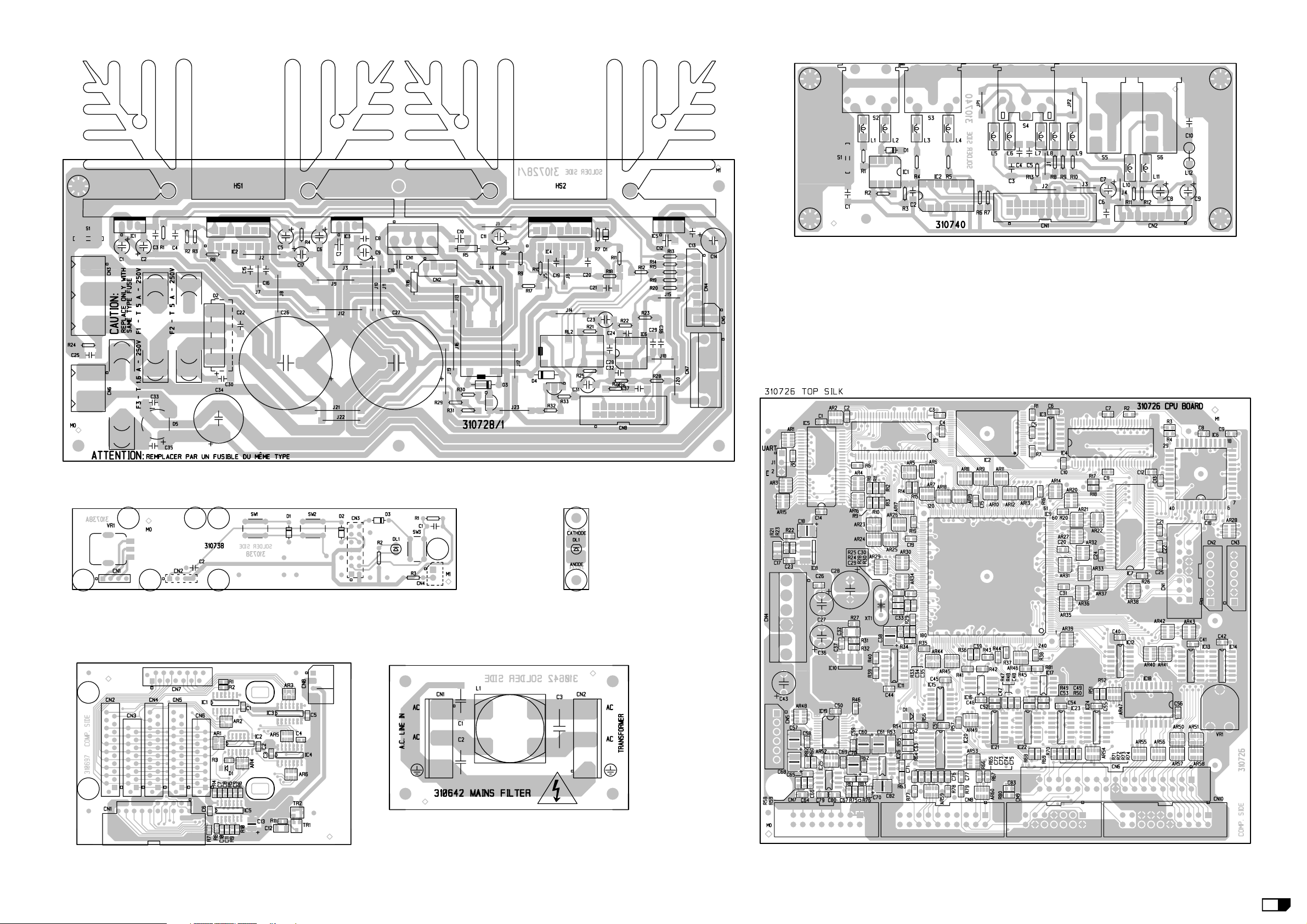
768197 Mains Filter Without Fuse Board Ass.y (Pcb#310642)
230568 * 10mH 250Vac 1A AC Line EMI Coil “Siemens”
140010 * 3 Contacts P=10 Vert Terminal Block
020493 * 100n 250Vac MKP EMI Capacitor “Siemens”
010545 * 4n7 250V Ceramic Capacitor (Iec-Ul-Csa)
230136 Transformer 230Vac 130W (EU)
230137 Transformer 115Vac 130W (US)
On/Off Led Board Assembly
810714 On/Off Led Board Assembly (PCB#310744)
841353 * Molex 5264/Tinned Dual Wire Cable L=10Cm
080752 * Led 3mm Red
Power Ampl.& Supply Board Ass.y
110020 T5A Fuse 5x20mm (EU)
110012 T1.6A Fuse 5x20mm (EU)
110021 T5A Fuse 6.3x32mm (US)
110055 T1.6A Fuse 6.3x32mm (US)
731083 Power Ampl.& Supply Board Ass.y (PCB#310728/1)
170717 * STK Amplifier Black Zinc Plated Heatsink
141102 * 6 Contacts Vert Male Connector
141101 * 4 Contacts Vert Male Connector
140929 * 9 Contacts Vert Male Connector
140917 * Molex 5267 2 Pos. Vert. Male Connector
140873 * 4 Contacts Vert Male Connector
140854 * 16 Contacts Vert Male Connector Din41651
140085 * 2 Contacts P=10 Vert Terminal Block
140010 * 3 Contacts P=10 Vert Terminal Block
120857 * 6.3mm Vertical Male Faston for Pcb
110305 * Relay 12V / 2 Switch 1A 250V
110304 * Relay 12V / 2 Switch 5A 250V
100969 * TDA7296 60W Power Amplifier
100919 * MC33078 Dual LN Operational Amplifier
100059 * 7805 +5V 1A Voltage Regulator
100045 * 7812 +12V 1A Voltage Regulator
100043 * 7912 -12V 1A Voltage Regulator
090183 * BC550C TO92 LN Npn Transistor
080605 * KBL02 4A 200V Rectifier Diode Bridge
080168 * W02M 1.5A Rectifier Diodes Bridge
080156 * 1N4002 1A 100V Rectifier Diode
080103 * 1N4148 100mA 75V Signal Diode
030805 * 2200u 25V 20% Vert Electrolytic Capacitor
030554 * 4700u 35v 20% Snap-In Electrolytic Capacitor
Phones Board Assembly
MDL735028 Phones Board Assembly (PCB#MDL310733)
140872 * Molex 5268 4 Pos. Male Hor. Conn. P=2.5mm
140217 * Horizontal Stereo Jack Slim Socket
140207 * Horizontal Female Jack Socket
Keyboard Assembly
MDL725006 88 Note Keyboard Assembly (Hammer)
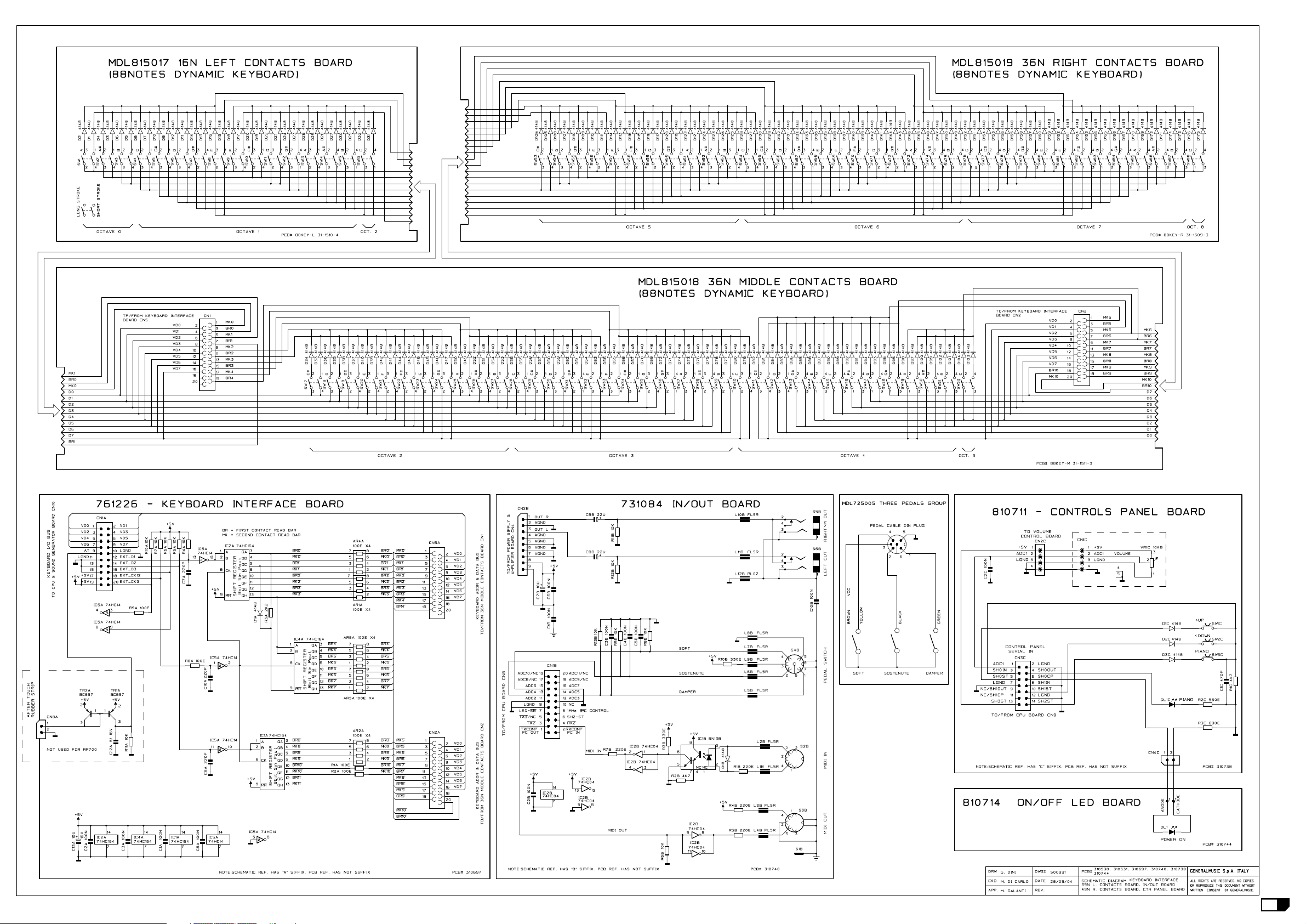
MDL815017 * 16 Note Left Contacts Board (Pcb#88Key-L 31-1510-4)
MDL815018 * 36 Note Middle Contacts Board (Pcb#88Key-M 31-1511-3)
MDL815019 * 36 Note Right Contacts Board (Pcb#88Key-R 31-1509-3)
MDL345076 ** 4Dual Contacts Rubber Strip
MDL345077 ** 12Dual Contacts Rubber Strip
MDL165001 * Leaf Spring
MDL155008 * First A Key
MDL155007 * Sharp Key
MDL155000 * C Key
MDL155001 * D Key
MDL155002 * E Key
MDL155003 * F Key
MDL155004 * G Key
MDL155005 * A Key
MDL155006 * B Key
MDL155009 * Last C Key
Keyboard Interface Board Assembly
761226 Keyboard Interface Board Assembly (Pcb#310697)
141018 * 20 Contacts Vert Female Connector
140918 * 2 Contacts Hor Male Connector
140852 * 20 Contacts Hor Male Connector Din41651
103015 * 74HC164D SOIC 8bit S To P Shift Register
103000 * 74HC14D Soic Hex Inverter Schmitt Trigger
091001 * BC857B/C TO236 Smd Pnp Transistor (9BB/C-3F/G)
081000 * PMLL4148 Smd 100mA 75V Signal Diode
Left Controls Panel Assembly
MDL825006 Left Controls Panel Assembly (Brown)
810711 * Control Panel Assembly (PCB#310738)
140956 ** 40 Pos. Headers Male H=8.5 Vert. Single Strip
140917 ** Molex 5267 2 Pos. Vert. Male Connector
140860 ** 14 Contacts Vert Male Dual In Line Strip
140529 ** Touch Switch 12V 50mA 0.25mm
080723 ** Led 3mm High Efficiency Tinted Red
080103 ** 1N4148 100mA 75V Signal Diode
074593 ** 10KB 9mm Vertical Rotary Potentiometer
MDL655098 * Brown Silkscreened Left Cheek Block
653531 * “< >” Silkscreened Dual Actuator
347404 * H=16.9mm 180°Red/Black Bicolour Knob
340972 * 9.6x13 Dark Gray Quad Actuator with Gem
120294 * WL3x6.5TC Black Zinc Plated Screw (no Tip)
CPU Board Assembly
761300 CPU Board Assembly (PCB#310726)
141102 * 6 Contacts Vert Male Connector
140910 * 14 Contacts Vert Male Connector Din41651
140874 * Single In Line Vert Male Strip (specify contacts)
140854 * 16 Contacts Vert Male Connector Din41651
140851 * 20 Contacts Vert Male Connector Din41651
106009 * LM1117DTX-ADJ Voltage Reg.0,8A TO252
106003 * MAX709 Power Monitor With Reset
106001 * MC33078P SOIC Dual Low Noise Op. Amp.
105015 * EPM3064ALC 44-4 EE Fpga
105012 * DRAKE - Cpu & Dsp Processor
104072 * TC58256AFT 3v3 TSOP 256MBit Nand Flash
104066 * K4S281632C-TC1L 128Mbitx16 Sync Dram 100MHz
104065 * IS41LV16100/S50T 16Mbitx16 Edo Dram
104052 * AT24C64 64Kbit Serial Access EEProm
103511 * I.C. 74HCT4051 8CH Analog Mux/Demux
103501 * 74HCT04 SOIC Hex Inverter
103066 * TLC548CD SOIC 8-bit A/D Converter
103052 * AD1854 Stereo 24bit Dac
103048 * 74LVC32D SOIC Quad 2-input Or Gate
103047 * 74LVC04 SOIC Hex Inverter
103012 * 74HC125D SOIC Quad Tri-State Buffer
081000 * PMLL4148 Smd 100mA 75V Signal Diode
055614 * 56K 1/16W 1% Smd Resistor 0603
055612 * 47K 1/16W 1% Smd Resistor 0603
055572 * 1K0 1/16w 1% Smd Resistor 0603
055570 * 820E 1/16w 1% Smd Resistor 0603
055562 * 390E 1/16w 1% Smd Resistor 0603
055552 * 150E 1/16w 1% Smd Resistor 0603
010728 * 11.2896MHz Quartz Resonator
In/Out Assembly
731092 In/Out Assembly
MDL665013 * Black Silkscreened Output Panel
MDL175011 * Output Panel Angular Support
MDL120012 * M3x6 TC Black Zinc Plated Self-Threading Screw
731084 * In/Out Board Assembly (PCB#310740)
230569 ** FL5R200PNT EMI Coil For Signal
230527 ** BL02RN2-R62 EMI Coil For Signal
140929 ** 9 Contacts Vert Male Connector
140851 ** 20 Contacts Vert Male Connector Din41651
140217 ** Jack Stereo Slim Horizontal Socket
140216 ** 6 Poles Din Horizontal Female Socket
140212 ** 5 Poles Din Horizontal Female Socket
120857 ** 6.3mm Vertical Male Faston for Pcb
100602 ** 74HC04 Hex Inverter
100035 ** 6N138 Optocoupler
080103 ** 1N4148 100mA 75V Signal Diode
Wiring Connections
770946 Cables Assembly
841390 * Micro-M/Latch 20x55CM P=1.27 Flat Cable
841389 * Latch 16x12.5CM P=1.27 Flat Cable +EMI Fer.
841388 * AWG18 Y/G Wire Jumper Fast/Tinned L=40mm
841387 * Latch 20x40CM P=1.27 Flat Cable
841355 * Molex 5264 4 Wires AWG20 Cable L=90CM
841351 * Latch14x110cm P=1.27 Flat Cable
841302 * Molex 5264 9 Wires AWG20 Cable L=40CM
841198 * Molex 5195 6Wires AWG18 Cable L=7.5CM
841196 * Wire Jumper AWG18 Y/G L=12.5CM (Eyel/Fast)
841026 * AWG18 Y/G Wire Jumper L=7.5 (Eyel/Fast)
840764 * AWG18 Yellow/Green Wire Jumper L=10CM
840563 * Latch 20x12.5CM P=1.27 Flat Cable
Note:
All dimensions are in mm unless otherwise specified.
The screw description is defined as follows:
type of screw + diameter + X + length + type of head
where type of screw is one of these:
M = Metric thread
B = Self-tapping screw for metal
WL = Self-tapping screw for wood
and type of head is one of these:
tc = cylinder Phillips head
ts = flared Phillips head
tt = rounded Phillips head
te = hexagonal nut head
tsp = flat flared Phillips head
tce = cylinder Allen hexagonal head
The washer description is defined as follow:
hole diameter + X + external diameter + X + thick
Each spare part is single quantity unless otherwise specified.
Asterisk prefix explanation:
Omitted = First level spare part.
(*) One asterisk = Second level, part of previous listed first level part.
(**) Two asterisk = Third level, part of previous listed second level part.
(***) Three asterisk = ............
Any request for not above mentioned part must encompass specific description
including:
1) Model name,
2) Section name,
3) Module code,
4) Reference name,
5) Quantity number.