8
Series 958 Embedded Linear Displacement Transducer
1080 North Crooks Road, Clawson, MI 48017 • Phone: 248-435-0700
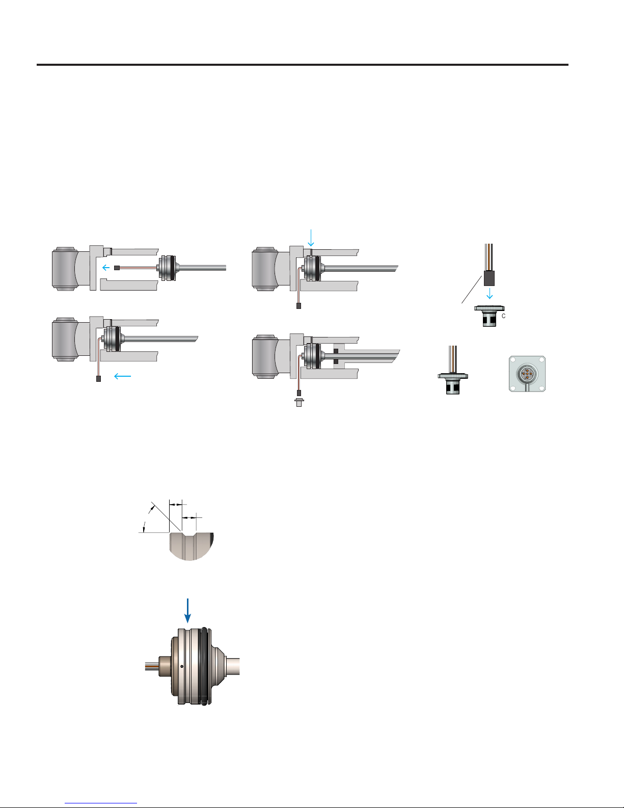
3.2: Pinouts and Wiring
There are six different connection options available. Refer to part numbers on unit in question for proper wiring.
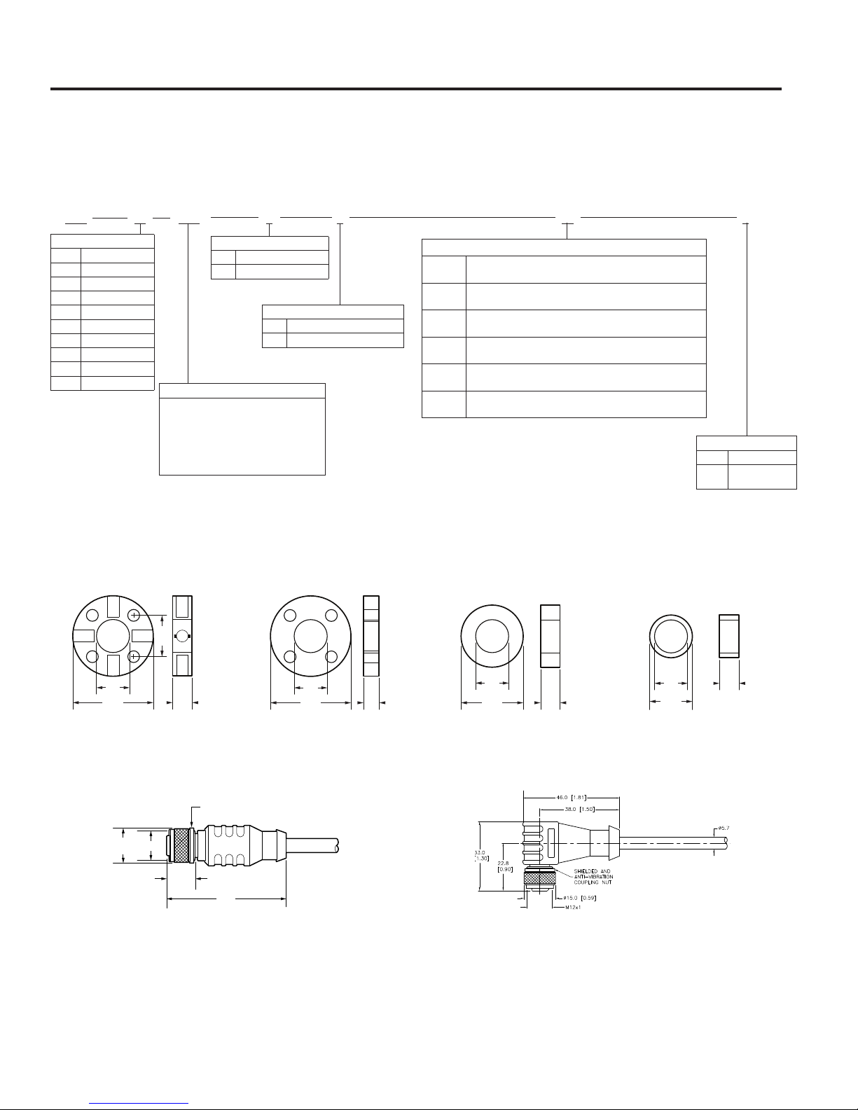
Figure 3-2: Pinouts and Wiring
Page 3 of 4
Z429 958A.DOR LDT Data Sheet
OUTPUT RESOLUTION
0 to 10 VDC: 16 bits (0.0015% of span)
0 to 5 VDC: 15 bits (0.0031% of span)
0.25 to 4.75 VDC: ~15 bits (0.0034% of span) (14.85 bits)
0.5 to 4.5 VDC: ~15 bits (0.0034% of span) (14.68 bits)
4 to 20 mA: 15.7 bits, calibrated for 3.5 to 21 mA (0 to 21 mA, 16 bits )
ISOLATION
Housing to Any Signal: 500 V
OUTPUT LOADING
Voltage: 2k Ω minimum
Current: 500 Ω maximum
CONNECTION OPTIONS
Integral Cable: Multi-conductor, 26 AWG, shielded, TPU jacket
5 Pin – M12: A-Code, Shell installed from "outside" cylinder
(IEC 61076-2-101)
Wire – Bare Leads: Multi-conductor, 26 AWG
WIRING DIAGRAMS
APPROVALS
lCE (Electromagnetic Compatibility)—2014/30/EU
lRoHS 2—2011/65/EU
lElectromagnetic compatibility - Part 6-4: Generic
standards – Emission standards for industrial environ-
ments—EN61000-6-4
lElectromagnetic compatibility (EMC) - Part 6-2: Generic
standards – Immunity for industrial environments—
EN61000-6-2
lAgricultural and forestry machinery—ISO 14982:1998
lRoad vehicles - electrical disturbances from nar-
rowband radiated electromagnetic energy — Part 5:
Stripline—ISO 11452-5
lRoad vehicles - Electrical disturbances from conduction
and coupling—ISO 7637-1/2/3
lEarthmoving Machinery—ISO 13766
lIndustrial Trucks—EN 12895
lRailway Applications—EN 50121-3-2
Pinouts and Wiring
(C
_
) Integral Cable
(M
_
S1) M12 – 5 Pin (A Code) (M
_
S2) M12 – 5 Pin (A Code) (M
_
S3) M12 – 5 Pin (A Code)
(W
_
) Wire – Bare Leads
* **
* * *
(G
_
S1) M12 – 5 Pin (A Code)
Analog Common (Green)
Analog Out (White)
Program (Orange)
Power Supply Common (Black)
VDC Power (Red)
Analog Common (Green)
Analog Out (White)
Program (Orange)
Power Supply Common (Black)
VDC Power (Red) VDC Power (Brown)
1
2
Power Supply Common (Blue)
Program (White)
3
Analog Out (Black)
4
Analog Common (Gray)
5
VDC Power (Brown)
1
2
Power Supply Common (Blue)
Analog Out (White)
3
Analog Common (Black)
4
Program (Gray)
5
Analog Common (Brown)
1
2
Power Supply Common (Blue)
VDC Power (White)
3
Analog Out (Black)
4
Program (Gray)
5
VDC Power (Brown)
1
2
Power Supply Common (Blue)
Analog Common (White)
3
Analog Out (Black)
4
Program (Gray)
5
* Insert length of wire.
958A LDT Linear Displacement Transducer
Power
Supply
8-30 VDC
958A
LDT
+ Input
- Input
Customer
Supplied Power
Power
Supply Common
Position
Output
Position
Common
Program Input
+
_
Power
Supply
8-30 VDC
958A
LDT
+ Input
Common
Customer
Supplied Power
Power
Supply Common
Position
Output
Program Input
+
_
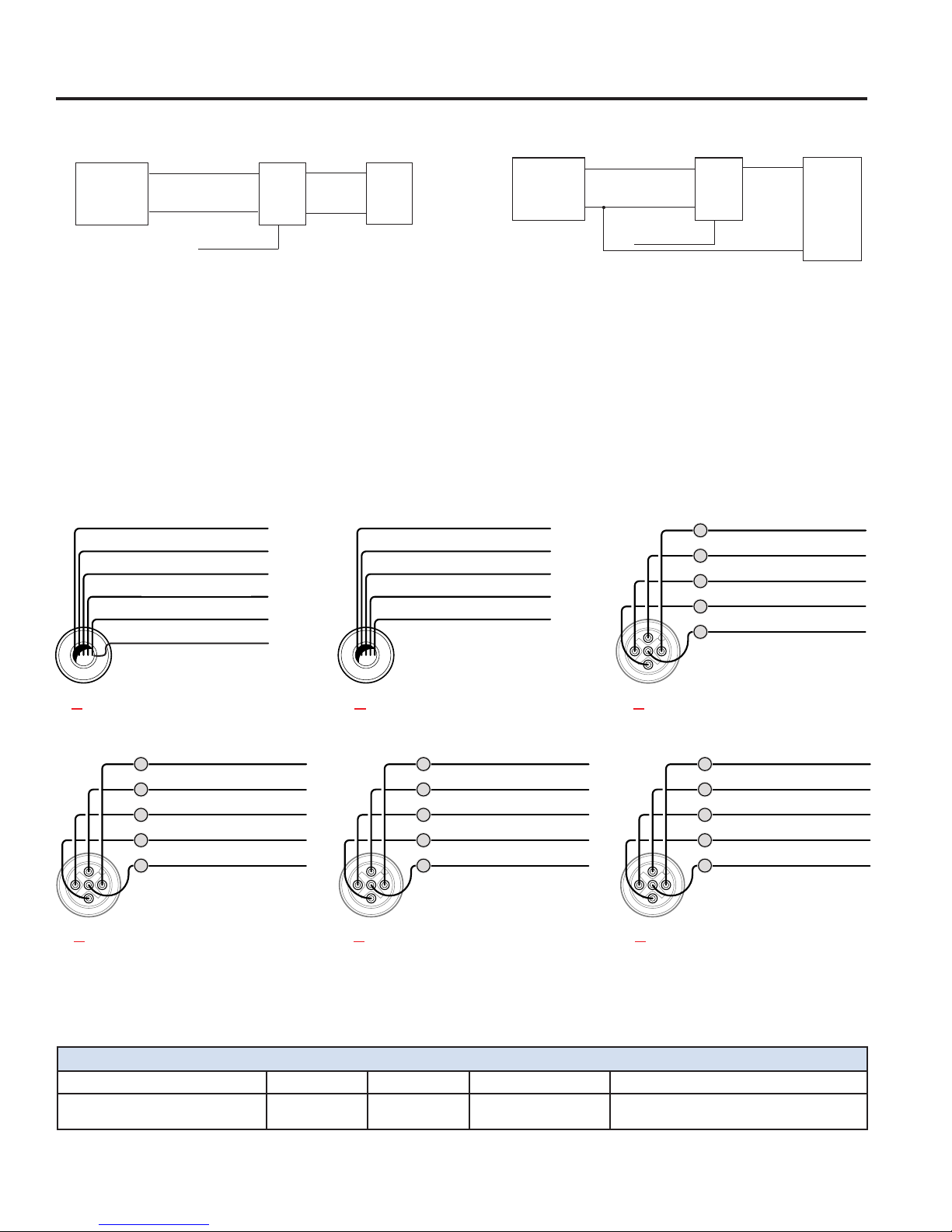
Single Ended Input
Figure 3-1: Wiring – Single Ended vs. Differential
The 958A-C is current sourcing, which allows the current to flow from the LDT into the user’s equipment.
Power
Supply
8-30 VDC
958A
LDT
+ Input
- Input
Customer
Supplied Power
Power
Supply Common
Position
Output
Position
Common
Program Input
+
_
Power
Supply
8-30 VDC
958A
LDT
+ Input
Common
Customer
Supplied Power
Power
Supply Common
Position
Output
Program Input
+
_
Differential Input
(Preferred Method)
(C) Integral Cable (W) Wire – Bare Leads (GS1) M12 – 5 Pin (A Code)
(MS1) M12 – 5 Pin (A Code) (MS2) M12 – 5 Pin (A Code) (MS3) M12 – 5 Pin (A Code)
indicates wire length. Refer to part numbers Appendix A for available options
Page 3 of 4
Z429 958A.DOR LDT Data Sheet
OUTPUT RESOLUTION
0 to 10 VDC: 16 bits (0.0015% of span)
0 to 5 VDC: 15 bits (0.0031% of span)
0.25 to 4.75 VDC: ~15 bits (0.0034% of span) (14.85 bits)
0.5 to 4.5 VDC: ~15 bits (0.0034% of span) (14.68 bits)
4 to 20 mA: 15.7 bits, calibrated for 3.5 to 21 mA (0 to 21 mA, 16 bits )
ISOLATION
Housing to Any Signal: 500 V
OUTPUT LOADING
Voltage: 2k Ω minimum
Current: 500 Ω maximum
CONNECTION OPTIONS
Integral Cable: Multi-conductor, 26 AWG, shielded, TPU jacket
5 Pin – M12: A-Code, Shell installed from "outside" cylinder
(IEC 61076-2-101)
Wire – Bare Leads: Multi-conductor, 26 AWG
WIRING DIAGRAMS
APPROVALS
lCE (Electromagnetic Compatibility)—2014/30/EU
lRoHS 2—2011/65/EU
lElectromagnetic compatibility - Part 6-4: Generic
standards – Emission standards for industrial environ-
ments—EN61000-6-4
lElectromagnetic compatibility (EMC) - Part 6-2: Generic
standards – Immunity for industrial environments—
EN61000-6-2
lAgricultural and forestry machinery—ISO 14982:1998
lRoad vehicles - electrical disturbances from nar-
rowband radiated electromagnetic energy — Part 5:
Stripline—ISO 11452-5
lRoad vehicles - Electrical disturbances from conduction
and coupling—ISO 7637-1/2/3
lEarthmoving Machinery—ISO 13766
lIndustrial Trucks—EN 12895
lRailway Applications—EN 50121-3-2
Pinouts and Wiring
(C
_
) Integral Cable
(M
_
S1) M12 – 5 Pin (A Code) (M
_
S2) M12 – 5 Pin (A Code) (M
_
S3) M12 – 5 Pin (A Code)
(W
_
) Wire – Bare Leads
* **
* * *
(G
_
S1) M12 – 5 Pin (A Code)
Analog Common (Green)
Analog Out (White)
Program (Orange)
Power Supply Common (Black)
VDC Power (Red)
Analog Common (Green)
Analog Out (White)
Program (Orange)
Power Supply Common (Black)
VDC Power (Red) VDC Power (Brown)
1
2
Power Supply Common (Blue)
Program (White)
3
Analog Out (Black)
4
Analog Common (Gray)
5
VDC Power (Brown)
1
2
Power Supply Common (Blue)
Analog Out (White)
3
Analog Common (Black)
4
Program (Gray)
5
Analog Common (Brown)
1
2
Power Supply Common (Blue)
VDC Power (White)
3
Analog Out (Black)
4
Program (Gray)
5
VDC Power (Brown)
1
2
Power Supply Common (Blue)
Analog Common (White)
3
Analog Out (Black)
4
Program (Gray)
5
* Insert length of wire.
958A LDT Linear Displacement Transducer
VDC Power (Brown)
Power Supply Common (Blue)
Program (White)
Analog Out (Black)
Analog Common (Gray)
No Connect (Pink)
Cable Specifications
Cable Type Gauge Jacket Temp Bend Radius
Multi-conductor Shielded 26 PUR -40° to 90°C Fixed Applications 1.05"
Moving Applications 3.15"